EP0243523B1 - Method of recording printing forms - Google Patents
Method of recording printing forms Download PDFInfo
- Publication number
- EP0243523B1 EP0243523B1 EP86105990A EP86105990A EP0243523B1 EP 0243523 B1 EP0243523 B1 EP 0243523B1 EP 86105990 A EP86105990 A EP 86105990A EP 86105990 A EP86105990 A EP 86105990A EP 0243523 B1 EP0243523 B1 EP 0243523B1
- Authority
- EP
- European Patent Office
- Prior art keywords
- signal
- image
- recording
- image signal
- signal sequence
- Prior art date
- Legal status (The legal status is an assumption and is not a legal conclusion. Google has not performed a legal analysis and makes no representation as to the accuracy of the status listed.)
- Expired - Lifetime
Links
Images


Classifications
-
- H—ELECTRICITY
- H04—ELECTRIC COMMUNICATION TECHNIQUE
- H04N—PICTORIAL COMMUNICATION, e.g. TELEVISION
- H04N1/00—Scanning, transmission or reproduction of documents or the like, e.g. facsimile transmission; Details thereof
- H04N1/387—Composing, repositioning or otherwise geometrically modifying originals
- H04N1/3872—Repositioning or masking
Definitions
- the present invention relates to the field of electronic reproduction technology and relates to a method and a device for the pixel-by-pixel recording of printing forms, in particular for multi-color printing, in which the recording signal required to control the recording element is retrieved from a signal source.
- individual templates for images and texts, from which printed pages are to be put together are first scanned optoelectronically and trichromatically in a color scanner in order to obtain color signals.
- a color correction calculator corrects the color signals in the case of four-color printing into color separation signals for the color separations "yellow”, “magenta”, “cyan” and “black”.
- the color separation signals indicate the required doses of the printing inks for printing.
- the color separation signals of the individual templates are digitized in color separation data and buffered. Images and texts are then assembled according to a layout plan in an electronic image processing system for the individual print pages, and the color separation data of all print pages of a print job are first stored in a data source for further use in the order required for recording.
- the recording device In the case of printing form recording for offset printing, the recording device is a black / white recorder, with which the screened color separations of the printed pages are exposed on a film material or directly on printing plates. In the case of printing form recording for gravure printing, the recording device, on the other hand, is an engraving system with which the screened color separations of the printed pages are engraved on printing cylinders.
- a goods catalog comprises a large number of printed pages and each printed page in turn consists of product images, product descriptions, titles and prices.
- each printed page in turn consists of product images, product descriptions, titles and prices.
- individual image or text templates are missing when the color separation data for the data source is developed, so that the relevant print pages of the goods catalog cannot be assembled and the color separation data of these print pages cannot be included in the database of the data source.
- printed pages of the goods catalog, whose color separation data are available in the database of the data source have to be updated with additional information, or entire printed pages have to be replaced by more current printed pages.
- a typical addition to information is, for example, the subsequent copying of current fonts, titles, prices, etc. onto the background of a printed page.
- GB-A 2 117 208 describes a method and a device for image and text integration on a printed page.
- An image original is scanned and the color data obtained in this way from the four color separations and an image control bit are combined to form data words of an image recording data sequence.
- a text template is scanned with a higher resolution than during image scanning, and the image data generated in the process and a text control bit are also combined into data words of a text recording data sequence.
- the image recording data sequence and the text recording data sequence are separated from one another by the representative control bits and processed differently before they are used to control the recording element, the recording of the text for improved reproduction being carried out with higher resolution than the image recording.
- Fig. 1 shows the basic block diagram of a recording device for printing forms.
- the recording device is the engraving unit or the separate engraving machine of an electronic engraving system for engraving screened color separations on printing cylinders for gravure printing.
- the recording device can also be any recorder for the point-by-line recording of printing forms on film material or for direct recording of printing forms.
- the engraving unit is fed from at least two data sources.
- the first data source is a storage device 1 (disk stack, magnetic tape, etc.), in which the color separation data of the individual color separations for the engraving of almost all printed pages of a print job are stored so that they can be called up pixel by pixel and line by line.
- a storage device 1 disk stack, magnetic tape, etc.
- the color separation data stored in the storage device 1 a large number of image and test templates were first optoelectronically and trichromatically scanned in a color scanner in accordance with the layout of the individual printed pages, and the color signals obtained in this way were color corrected in accordance with the laws of multicolor printing subtractive color mixing into color separation signals and then converted into color separation data by an analog / digital conversion.
- the individual images and texts were then assembled according to the layout plans of the printed pages, for example in an electronic image processing system, by combining the color separation data into entire printed pages, and the combined color separation data was stored in the memory device 1 pixel by pixel and image line by line.
- image data obtained by scanning black-and-white originals can also be stored in the storage device 1, so that the image data of the storage device 1, which e.g. each have a word length of 8 bits.
- the image data of individual printed pages may be missing in the storage device 1, specifically from those printed pages for which the images and / or texts were not yet available at the time the image data was processed.
- the second data source is designed as a scanner 2 for black / white originals or non-screened or screened color separations.
- the scanner 2 is, for example, the scanner unit or the separate scanner of the electronic engraving system.
- This scanner 2 consists of a scanning drum 3, which is driven by a motor 4, a pulse generator 5 connected to the drum shaft, and an optoelectronic scanning element 6 for Ge Winning an image signal by dot-by-dot and line-by-line scanning of a template 7 arranged on the scanning drum 3 and an A / D converter 8 connected to the scanning element 6, which digitizes the image signal in image data with, for example, a word length of 10 bits.
- a feed device consisting of a feed motor 9 and a spindle 9 ', the scanning element 6 is moved axially along the scanning drum 3 during the scanning of the original.
- the pulse generator 5 With each revolution of the scanning drum 3, the pulse generator 5 generates a "scan start" signal which marks the desired scan start on the original 7.
- the second data source (2) can also be a color scanner or a memory device in which the image data obtained by optoelectronic scanning of a template and digitization are temporarily stored.
- the scanner 2 supplies the current image data which are not stored in the memory device 1 and which are to be taken into account online when engraving the printing form.
- the scanner 2 supplies the current image data of an entire printing page which is intended to replace a printing page contained in the database of the storage device 1 on the printing form or to be added to the printing form instead of an empty page.
- the template 7 scanned in the scanner 2 is a current print page template with halftone and line areas, and one or the other data source (1 or 2) is involved in the engraving of the printing form from print page to print page, subsequently with switching Operation.
- the scanner 2 supplies the current image data of a line information, e.g. B. a font that is to be copied onto the printing form in the background of a print page contained in the database of the storage device 1.
- a line information e.g. B. a font that is to be copied onto the printing form in the background of a print page contained in the database of the storage device 1.
- the template 7 scanned in the scanner 2 is a line template, and both data sources (1 or 2) are involved in the engraving of the printing form at the time of copying in, hereinafter referred to as overlay operation.
- the image data sequences read out from the memory device 1 and the scanner 2 are fed via data buses 10 and 11 to a signal processing circuit 12 of the engraving unit, in which a resultant recording data sequence is generated on a data bus 13 from the image data sequences .
- the resulting recording data sequence is converted into an analog recording signal in a D / A converter 14 and amplified in an engraving amplifier 15.
- an engraving amplifier 15 In the engraving amplifier 15, a raster signal determining the printing raster to be engraved is superimposed on the recording signal.
- the engraving signal formed from the recording signal and raster signal controls z.
- the recording signal controls the depth of penetration of the engraving engraving into the surface of the printing cylinder 17 and thus the depths of the printing cylinder engraved cells or the engraved tonal values between "black” and "white”.
- the pressure cylinder 17 is driven by a motor 18.
- the engraving member 16 is guided axially past the printing cylinder 17 with the aid of a feed device consisting of a motor 19 and a spindle 19 '.
- a pulse generator 20 coupled to the shaft of the printing cylinder 17 generates a synchronous signal on a line 21.
- the rotary movements of the scanning drum 3 of the scanner 2 and the printing cylinder 17 are synchronized with one another in a suitable manner. If the scanner 2 is the integrated scanning unit of the engraving system, the scanning drum 3 and printing cylinder 17 are mechanically coupled by a shaft, and one of the drive motors can be omitted. If the scanner 2 is the separate scanning machine of the engraving system or any scanner, the synchronization of the rotary movements is achieved, for example, by frequency-controlled converter drives for the scanning drum 3 and printing cylinder 17.
- the electromagnetic engraving element 16 can also be a laser or electron beam generator modulated by the engraving signal.
- Each engraved image line 23 (circumferential line) is composed of three partial image lines of the individual printed pages 22.
- a cylinder assignment scheme also called imposition scheme or cylinder layout, which is created by a reproduction specialist, defines the desired positions of the printed pages 22 relative to one another and on the printing cylinder 17.
- the signal path 25 for the image data sequence from the memory device 1 consists of a gradation stage 26 with a halftone gradation, a mask register 27 and an image line memory device 28.
- the signal path 29 for the image data sequence from the scanner 2 points an electronic switch 30, a gradation stage 31 with a halftone gradation, a further gradation stage 32 with a line gradation, a mask register 33 and also an image line storage device 34.
- Each image line storage device 28 or 34 can store the engraving information for the cells of an entire image line 23, with each storage location being assigned an engraving location in the image line 23 on the printing cylinder 17.
- the image line storage devices 28 and 34 are expediently designed as removable storage with at least two storage areas in each case.
- the engraving information of the individual image lines is thereby alternately written into the two memory areas and alternately read out of the memory areas. In this way, when the engraving information for an image line is written into one of the storage areas, the engraving information of the previous image line can already be read out and engraved from the other storage area, thereby considerably reducing the engraving time for the printing cylinder 17.
- the signal control in the signal path 25 also includes a read control unit 35 for the memory device 1, an assignment control unit 36 and a write control unit 37 for the image line storage unit 28.
- the read control unit 35, the assignment control unit 36 and the write control unit 37 are synchronized with one another via lines 38 and 39.
- the signal path 29 also includes a read control unit 40 for the scanner 2, an assignment control unit 41 and a write control unit 42 for the image line storage device 34, which are synchronized with one another via the lines 43 and 44.
- a common read control unit 45 is provided for the image line storage devices 28 and 34.
- the data outputs 46 and 47 of the image line storage devices 28 and 34 are connected via data buses 48 and 49 to the address input 50 of a logic stage 51.
- the data output 52 of the logic stage 51 forms the output of the signal processing circuit 12, which is connected via the data bus 13 to the input of the D / A converter 14.
- the image data sequences are read and processed online, pixel by pixel and image line, from the memory device 1 and / or from the scanner 2.
- the read control unit 35 In order to read out the memory device 1, the read control unit 35 generates a read clock sequence Ti which can be switched on and off and which is supplied to the memory device 1 via a line 53. This read clock sequence Ti is switched off each time the data of an image line is written into the image line storage device 28 and is only switched on again for writing the data of the following image line when a storage area of the image line storage device 28 can hold new data. This state is signaled to the read control unit 35 via a line 54 from the read control unit 45.
- the read control unit 40 To read the scanner 2, the read control unit 40 generates a further read clock sequence T 2 which can be switched on and off and which is fed to the A / D converter 8 of the scanner 2 as a sample clock via a line 55.
- the pulse generator 5 of the scanner 2 emits the "scan start” signal at each revolution of the scanning drum 3 or at the start of scanning on each image line of the original 7, which signal is sent to the read control unit 40 via a line 56.
- Each "scan start” signal initiates the reading process for the image data of a scanned image line by starting the read clock sequence T 2 with the "scan start” signal in the read control unit 40.
- the reading out of the image data from the scanner 2 is stopped at the end of each scanned image line by the pulse generator 5 additionally emitting a signal "scanning end" at the desired end of the image line, which is fed to the reading control unit 40 via a line 57 and there the reading clock sequence T 2 interrupts.
- the reading out of the image data from the storage device 1, their processing and the writing of the processed data into the image line storage device 28 take place synchronously, likewise the reading out of the image data from the scanner 2, the processing and the writing into the image line storage device 34 the reading processes of the image data from the storage device 1 and the scanner 2 are not synchronized, but are adapted to the requirements, the two image line storage devices 28 and 34 simultaneously serving as data buffers.
- the data of an image line to be engraved, which are temporarily stored in the two image line storage devices 28 and 34, are read out synchronously with the raster signal generation in the engraving amplifier 15 and with the rotary movement of the printing cylinder 17 or with the engraving of the cells.
- the synchronous signal formed in the pulse generator 20 is fed via line 21 to the engraving amplifier 15 and to the common read control unit 45 for the image line storage devices 28 and 34.
- the read control unit 45 generates the common read addresses for both image line storage devices 28 and 34 on the address bus 58 and also a common read clock sequence T 3 on a line 59.
- the read clock sequence T 3 is started in each case when in the image line storage means 28 the data of an entire image line are inscribed. This state is signaled to the read control unit 45 via a line 60 from the write control unit 37.
- the modified image data are successively stored in the mask register 27, frame by frame, by frame.
- the created source assignment scheme for the storage device 1 was previously programmed into the assignment control unit 36, in which, as has already been explained above, it is determined which image data of the storage device 1 are to be considered as engraving information (valid image data) and which should be disregarded (invalid) Image data or mask data).
- the assignment control unit 36 always generates a mask signal on a line 61 when an image data temporarily stored in the mask register 27 is to be regarded as an image data that is invalid for the engraving.
- the mask signal on line 61 causes the relevant image data to be replaced by a mask data with a constant value of, for example, 255.
- this value of the mask date is selected such that it lies outside the value range of the image data that contains the actual engraving information.
- an image date temporarily stored in the mask register 27 is a valid image date, the mask signal is omitted and the image date is not influenced.
- Image data and mask data of an image line are written into the image line storage device 28 pixel by pixel via the data input 62 in the order determined by the storage device 1 and the associated source assignment scheme.
- the write control unit 37 generates the corresponding write addresses on an address bus 63 and a write clock sequence T 4 on a line 64.
- the image data read out from the scanner 2 initially arrive at the electronic switch 30, which, as will be explained later, can be switched over by the source assignment scheme of the scanner 2.
- the assignment control unit 41 generates a corresponding control signal which is fed to the electronic changeover switch 30 via a line 65.
- the image data with a word length of 10 bits reach the gradation level 31 and are there in accordance with the halftone gradation in image data with a word length also encoded by 8 bits and a value range from 1 (black) to 254 (white), the value 255 again being excluded as engraving information.
- the source assignment scheme set up for the scanner 2 has also already been programmed into the assignment control unit 41.
- the modified image data arrive at the mask register 33, in which, as already explained for the mask register 27 of the signal path 25, invalid image data are replaced with mask data on a line 67 by mask data in accordance with the source assignment scheme for the scanner 2 and valid image data remain unaffected.
- Image data and mask data of each image line of the scanned print page are written into the addresses of the image line storage device 34 which correspond to the engraving position of the relevant image line or print page on the printing cylinder 17, which is determined by the source assignment scheme of the scanner 2 or by the cylinder assignment scheme.
- the write control unit 42 generates the corresponding write addresses on an address bus 68 and a write clock sequence T 5 on a line 69.
- the source assignment scheme of the scanner 2 additionally contains the information about the required starting address for the Image data of the print page in the image line storage device 34, which the write control unit 42 via a Lei device 70 is communicated by the assignment control unit 41.
- a line template with positive, negative or mixed positive / negative line elements is scanned in the scanner 2, and the image data obtained in this way reach the gradation level 32 via the switched electronic switch 30.
- the gradation level 32 contains a line gradation for positive, for negative or for mixed positive and negative line elements according to the scanned line template.
- the gradation level 32 can also contain all three different line gradations. In this case, the line gradation required in each case is selected by a command or else automatically based on the source assignment scheme of scanner 2 if different types of originals are scanned in scanner 2 at the same time.
- the line gradation is designed in such a way that the line template is automatically masked when the original is scanned in the scanner 2, by interpreting certain density areas of the original as information to be engraved (valid image data) and other density areas as a mask (invalid image data) will.
- the input value range and the output value range of the line gradation are each subdivided into an information area between "black” and "white” and into a mask area.
- Image data of the scanned line template that fall in the input-side information area are interpreted as valid image data and, in accordance with the course of the gradation curve, are converted into value data in image data of the output-side information area.
- the image data and mask data output by the gradation stage 32 also pass through the mask register 33 and are written into the image line storage device 34, as described.
- image and / or mask data of a pixel or of a well to be engraved appear simultaneously at the address input 50 of the linkage stage 51.
- the data arriving at the same time become at the address input 50 an input address with a word length of 16 bits combined.
- the data of the scanner 2 form the low-order bits from 2 ° to 27 and the data of the memory device 1 the high-order bits from 2 8 to 2 15 of the input address.
- the mask date of a pixel or cell involved in the formation of an input address determines whether the engraving information for the cell in question is to be formed from the image data of one or the other data source. If, on the other hand, the input address does not have a mask date, the engraving information for the well in question is formed from the image data of both data sources.
- the link stage 51 is constructed as a look-up table (LUT).
- the link stage 51 contains for every possible combination of image data and / or mask data at the address input 50 of the link stage 51 or for each input address Record date with a word length of 8 bits, which represents the desired engraving information for the relevant cell.
- the engraving system operates in the switching mode, the linkage stage 51 has the function of a changeover switch for engraving information, and when the printing cylinder 17 is engraved, print pages are processed current print pages replaced or current print pages on the printing cylinder 17 added. This mode of operation is once again explained schematically with reference to FIG. 3.
- the engraving unit is fed exclusively from the other data source.
- Both data sources are involved in the engraving of a printing cylinder 17 if the input address of the link stage 51 is formed only from valid image data. Then there is the link Level 51 a recording date, which is either formed from the respectively valid image data of both data sources with the same or different weighting or has a freely selectable value.
- the engraving system works in the superimposition mode, the linking stage 51 performs the function of mixing or superimposing engraving information, and when engraving the printing cylinder 17, for example, a current font is engraved in the background of a printed page. This mode of operation is once again explained schematically with reference to FIG. 4.
- the values of the recording data can be selected in an advantageous manner so that, for example, any course from the background to the font can be achieved in the contour area of the font when copying writing into a background to let.
- the link stage 51 does not provide any recording data and an empty page is "engraved" on the printing cylinder 17.
- the invention is not limited to the exemplary embodiment described for an engraving system.
- the scanner 2 can also be equipped with a plurality of scanning elements, so that a plurality of originals arranged side by side on the scanning drum 3 can be scanned at the same time.
- the scanner 2 has additional memory registers with which the image data of the individual scan channels are read out of the scanner 2 in multiplex mode and fed to the signal processing circuit 12.
- the automatic masking of a scanned original according to the invention by different interpretation of the density values of the original based on line gradations can of course also be used outside of the engraving system.
- the engraving system shown works with a single engraving element.
- FIG. 2 shows the courses of the line gradations stored in the gradation stage 32 of the engraving system according to FIG. 1 for the automatic masking of a line template scanned in the scanner 2.
- FIG. 2 a shows the special gradation curve for line templates with positive line elements, positive line elements being understood as black line elements (black writing) on a light background.
- input image data which fall into the input-side information area 71 are engraved information (valid image data) and input image data which fall into the mask area 72 fall, interpreted as mask data (invalid image data).
- the relationship between input image data and output image data is determined by the course of the gradation curve between the calibration points, which is determined by the respective printing conditions.
- 2 b shows the gradation curve for line templates with negative line elements, negative line elements being understood to mean white line elements (white writing) on a dark background.
- 2 c shows the gradation curve for line templates with mixed positive / negative line elements.
- an average density range of the stroke template between the density values of the calibration point "black” and the calibration point “white” is now interpreted as the template background.
- the mask area 72 thus lies within the original part of the information area 71 of the line gradations, provided for better contour reproduction, for positive or for negative line elements.
- the density range of the mask area 72 is determined such that all density fluctuations of the original background fall into the mask area 72.
- These partial areas can be the same or different.
- a decoding stage 75 is provided in the engraving system of FIG. 1 between the image line storage device 34 and the linking stage 51, which in FIG. 1 only. is indicated by dashed lines, since it is only effective in the case of dash gradation for mixed positive / negative dash elements.
- the decoding stage 75 contains corresponding correction gradations, which can also be programmed into the linking stage 51.
- Fig. 3 shows a diagram for the switching operation of the engraving system, on which this function will be explained again.
- a) three successive printed pages A, B and C are shown, the image data of which are stored in the memory device 1.
- a current print page D is indicated, the image data of which are obtained by scanning the corresponding print page templates in the scanner 2.
- the current print page D is to replace the print page B contained in the database of the storage device 1, so that the print pages A, D and C lying one behind the other are to be engraved on the recording surface 77 of the print cylinder 17, as indicated in c).
- the associated source assignment scheme for the memory device 1, which is stored in the assignment control unit 36, is shown in d) and e).
- the corresponding source assignment scheme for the scanner 2, which is programmed into the assignment control unit 41, is given in f) or g).
- Corresponding partial areas 76 are assigned to the printed pages in the source assignment schemes. The letters in the partial areas 76 are intended to indicate that the printing pages in question are to be engraved, while the crossed-out partial areas 76 indicate that the associated printing pages should not be taken into account in the engraving.
- an image line formed from the valid image data of the storage device 1 for the printed pages A and C and from mask data X is shown, which is stored in the image line storage device 28 of the engraving system.
- the representation j) shows an image line composed of the valid image data of the scanner 2 for the print side D and likewise of mask data X, which is temporarily stored in the image line storage device 34.
- the order of image data and mask data in each image line is determined by the associated source assignment scheme e) or g).
- Image and mask data of both image lines arrive at the linking stage 51 of the engraving system. As already explained, in switching operation only the valid image data are forwarded through the linking stage 51 as recording data, so that the image line shown in j) is engraved on the printing cylinder 17.
- Fig. 4 shows the corresponding scheme for the overlay operation of the engraving system.
- the successive printed pages A, B and C are again shown, the image data of which are stored in the memory device 1.
- a line template 78 with a current font E is indicated in b).
- the image data of the line template 78 are obtained with the aid of the scanner 2.
- the current font E of the line template 78 which is not contained in the database of the storage device 1, should be copied into the background of the printed page A, while the printed pages B and C are to be engraved unchanged.
- the arrangement of the printing pages A, B and C to be engraved on the printing cylinder 17 is shown in c), wherein on the printing page A by "A" a pure background area and by "A + E" an overlay area for background and writing is to be symbolized.
- the source assignment scheme for the storage device 1 is again shown in d) or e) and the relevant source assignment scheme for the scanner 2 in f) or g).
- an image line formed from the image data A, B and C of the printed pages A, B and C stored in the memory device 1 is shown, which is temporarily stored in the image line memory device 28.
- the representation i) shows an image line composed of the image data E obtained from the scanner 2 for the font E of the line template 78 and from mask data X, which is stored in the image line storage device 34.
- the difference to the mask data generation in the switching operation explained above is that only the mask data 79 are generated by the source assignment scheme of the scanner 2, while the mask data 80 within the line template 78 with the aid of the line gradation according to the invention arise.
- Finally j) shows the associated engraved image line for the printed page arrangement according to c).
- FIG. 5 shows a graphical representation, on the basis of which the advantages of the free assignment of recording data to the input addresses of the link stage 51, for example when copying line elements, in particular fonts, into the background of a printed page are to be explained.
- 5 a shows a printed page 81 forming the background, into which a line element 82 of a line template is to be copied.
- Line 83 indicates the direction of an image line to be engraved or the engraving direction.
- the diagram shown in FIG. 5 b shows the course of the image signal values a supplied by the memory device 1 for the background of the printed page 81 with constant density, plotted over the image line 83 or over the time t.
- the diagram in FIG. 5 c shows the course of the image signal values b obtained by scanning the line template over the corresponding image line 83, the course 84 changing when the document background is scanned, the course 85 when scanning the contour of the line element 82 and the course 86 results when scanning the line element 82 itself.
- the dashed line is intended to indicate the mask threshold of the line gradation, the recording signal values c corresponding to the image signal values a for image signal values b below the mask threshold and the recording signal values c for image signal values b lying above the mask threshold from a combination of the image signal values a and b are formed.
- the input addresses of the linkage stage 51 are formed from the image signal values a and b of the memory device 1 and the scanner 2, under which respectively assigned recording signal values c are stored.
- the assignment of recording signal values c and input addresses in the link stage 51 can be made in such a way that any desired transition from the background to the line element and vice versa can advantageously be produced, as a result of which the reproduction quality is considerably increased.
- 5 d in the correspondingly selected recording signal values c over the image line 83 shows various possibilities for transitions on a line element 82.
- the course 87 can be used to emphasize, for example, writing on a background, while the course 88 achieves softer transitions.
- disturbing hems on contours that occur during conventional copying with the aid of control masks are advantageously avoided.
- 5 e shows, as prior art, the result when copying in with a control mask which switches the image signal 89 of the background and the image signal 90 of a line element to be copied in at a certain threshold 91. In this case, disturbing seams 92 arise on the contours of the line element copied in.
- FIG. 6 shows a development of the engraving system according to FIG. 1, with which several engraving strands, in the example shown three engraving strands 94, can be engraved on the printing cylinder 17 at the same time.
- the engraving system has three separate engraving channels I, II and III for the three engraving strands 94.
- Each signal path 25 or 29 is compared to the embodiment in FIG. 1 corresponding to the additional number of two engraving strands by two mask registers 27 'and 27 "or 33' and 33" and by two image line storage devices 28 'and 28 "or . 34 'and 34 "extended.
- Each engraving channel I, II and III has a mask register 27, 27 'or 27 “and an image line storage device 28, 28' or 28" of the signal path 25 and a corresponding mask register 33, 33 'or 33 “ and a corresponding image line storage device 34, 34 'or 34 "of the signal path 29 is assigned.
- Each engraving channel I, II and III also has a linkage stage 51, 51 'or 51 ", a D / A converter 14, 14' or 14", an engraving amplifier 15, 15 'or 15 “and an engraving element 16, 16 'or 16 ".
- the storage device 1 now contains the image data for all engraving strands.
- a distributor stage 95 is provided for distributing the image data read from the memory device 1 to the engraving channels I, II and 111 of the signal path 25, which is controlled by the assignment control unit 36 via a line 96 depending on the source assignment scheme stored there.
- a distributor stage 97 is provided for the signal path 29, with which the image data supplied by the scanner 2 are distributed to the engraving channels I, 11 and 111.
- the distribution stage 97 is switched over by a line 98 from the assignment control unit 41 depending on the source assignment scheme stored there.
- the method according to the invention advantageously enables universal operation of the engraving system.
- engraving for example, print pages in selectable engraving lines can be replaced by current printing pages or current printing pages can be supplemented, while fonts can be simultaneously copied into printing pages in the same engraving lines or in other selected engraving lines.
Landscapes
- Engineering & Computer Science (AREA)
- Multimedia (AREA)
- Signal Processing (AREA)
- Manufacture Or Reproduction Of Printing Formes (AREA)
- Editing Of Facsimile Originals (AREA)
- Facsimile Image Signal Circuits (AREA)
- Storing Facsimile Image Data (AREA)
- Color Image Communication Systems (AREA)
- Preparing Plates And Mask In Photomechanical Process (AREA)
- Color Printing (AREA)
- Ink Jet (AREA)
Abstract
Description
Die vorliegende Erfindung bezieht sich auf das Gebiet der elektronischen Reproduktionstechnik und betrifft ein Verfahren und eine Einrichtung zur bildpunkt- und bildlinienweisen Aufzeichnung von Druckformen, insbesondere für den Mehrfarbendruck, bei denen das zur Steuerung des Aufzeichnungsorgans benötigte Aufzeichnungssignal aus einer Signalquelle abgerufen wird.The present invention relates to the field of electronic reproduction technology and relates to a method and a device for the pixel-by-pixel recording of printing forms, in particular for multi-color printing, in which the recording signal required to control the recording element is retrieved from a signal source.
Vor der Druckform-Aufzeichnung werden zunächst einzelne Vorlagen für Bilder und Texte, aus denen Druckseiten zusammengestellt werden sollen, in einem Farb-Abtaster optoelektronisch und trichromatisch abgetastet, um Farbsignale zu gewinnen. Ein Farbkorrektur-Rechnur korrigiert die Farbsignale im Falle des Vierfarbendrucks in Farbauszugssignale für die Farbauszüge "Gelb", "Magenta", "Cyan" und "Schwarz". Die Farbauszugssignale geben die erforderlichen Dosierungen der Druckfarben für den Druck an. Die Farbauszugssignale der einzelnen Vorlagen werden in Farbauszugsdaten digitalisiert und zwischengespeichert. Bilder und Texte werden dann nach einem Layoutplan in einer elektronischen Bildverarbeitungsanlage zu den einzelnen Druckseiten montiert und die Farbauszugsdaten sämtlicher Druckseiten eines Druckauftrages in der für die Aufzeichnung benötigten Reihenfolge zunächst in einer Datenquelle zur weiteren Verwendung abgelegt.Before recording the printing form, individual templates for images and texts, from which printed pages are to be put together, are first scanned optoelectronically and trichromatically in a color scanner in order to obtain color signals. A color correction calculator corrects the color signals in the case of four-color printing into color separation signals for the color separations "yellow", "magenta", "cyan" and "black". The color separation signals indicate the required doses of the printing inks for printing. The color separation signals of the individual templates are digitized in color separation data and buffered. Images and texts are then assembled according to a layout plan in an electronic image processing system for the individual print pages, and the color separation data of all print pages of a print job are first stored in a data source for further use in the order required for recording.
Diese Arbeitsschritte erfolgen im allgemeinen lange Zeit vor der Druckform-Aufzeichnung, bei der die Farbauszugsdaten aus der Datenquelle ausgelesen und zur Steuerung des Aufzeichnungsorgans einer Aufzeichnungs-Einrichtung verwendet werden.These work steps generally take place long before the printing form recording, in which the color separation data are read from the data source and used to control the recording element of a recording device.
Im Falle der Druckform-Aufzeichnung für den Offsetdruck ist die Aufzeichnungs-Einrichtung ein Schwarz/Weiß-Recorder, mit dem die gerasterten Farbauszüge der Druckseiten auf ein Filmmaterial oder direkt auf Druckplatten belichtet werden. Bei der Druck form-Aufzeichnung für den Tiefdruck ist die Aufzeichnungs-Einrichtung dagegen eine Gravieranlage, mit der die gerasterten Farbauszüge der Druckseiten auf Druckzylinder graviert werden.In the case of printing form recording for offset printing, the recording device is a black / white recorder, with which the screened color separations of the printed pages are exposed on a film material or directly on printing plates. In the case of printing form recording for gravure printing, the recording device, on the other hand, is an engraving system with which the screened color separations of the printed pages are engraved on printing cylinders.
Das zu lösende Problem soll am Beispiel der Druckform-Aufzeichnung für einen Warenkatalog erläutert werden. Ein Warenkatalog umfaßt eine Vielzahl von Druckseiten und jede Druckseite besteht wiederum aus Warenabbildungen, Warenbeschreibungen, Titel und Preisangaben. In der Praxis kommt es häufig vor, daß bei der Erarbeitung der Farbauszugsdaten für die Datenquelle noch einzelne Bild- oder Textvorlagen fehlen, so daß die betreffenden Druckseiten des Warenkatalogs nicht montiert und die Farbauszugsdaten dieser Druckseiten nicht in den Datenbestand der Datenquelle aufgenommen werden können. Ebenso kommt es vor, daß Druckseiten des Warenkatalogs, deren Farbauszugsdaten im Datenbestand der Datenquelle vorhanden sind, durch ergänzende Informationen aktualisiert oder ganze Druckseiten durch aktuellere Druckseiten ausgetauscht werden müssen. Eine typische Informationsergänzung ist beispielsweise das nachträgliche Einkopieren von aktuellen Schriften, Titeln, Preisen usw. auf den Hintergrund einer Druckseite.The problem to be solved will be explained using the example of printing form recording for a goods catalog. A goods catalog comprises a large number of printed pages and each printed page in turn consists of product images, product descriptions, titles and prices. In practice, it is often the case that individual image or text templates are missing when the color separation data for the data source is developed, so that the relevant print pages of the goods catalog cannot be assembled and the color separation data of these print pages cannot be included in the database of the data source. It also happens that printed pages of the goods catalog, whose color separation data are available in the database of the data source, have to be updated with additional information, or entire printed pages have to be replaced by more current printed pages. A typical addition to information is, for example, the subsequent copying of current fonts, titles, prices, etc. onto the background of a printed page.
Bei derartigen aktuellen Änderungen und/oder Ergänzungen eines Druckauftrages war es bisher erforderlich, die elektronische Seitenmontage mit den geänderten oder aktualisierten Bildern und Texten zu wiederholen, die neuen Farbauszugsdaten in den Datenbestand der Datenquelle zu übernehmen und den gesamten Datenbestand durch einen Sortierlauf zu überarbeiten. Da die Vorlagen der aktuellen Bilder und Texte in den meisten Fällen Filmvorlagen sind, bei der elektronischen Seitenmontage aber mit Farbauszugsdaten, also filmlos, gearbeitet wird, müssen die aktuellen Vorlagen dann auch noch vor der elektronischen Seitenmontage durch optische Abtastung und Digitalisierung in Farbauszugsdaten umgewandelt werden. Diese Vorgehensweise ist zeitaufwendig und bei der geforderten Aktualität in der Druckindustrie kaum vertretbar.In the case of such current changes and / or additions to a print job, it was previously necessary to repeat the electronic page assembly with the changed or updated images and texts, to adopt the new color separation data in the database of the data source and to rework the entire database with a sorting run. Since the templates of the current images and texts are mostly film templates, but in the case of electronic page assembly, color separation data is used, i.e. without film, so the current templates must also be converted to color separation data by optical scanning and digitization before electronic page assembly. This procedure is time-consuming and, given the required topicality in the printing industry, is hardly justifiable.
Aufgabe der vorliegenden Erfindung ist es daher, zur Behebung der genannten Nachteile ein Verfahren zur Aufzeichnung von Druckformen und einer Aufzeichnungs-Einrichtung anzugeben, mit denen direkt bei der Druckform-Aufzeichnung aktuelle Änderungen und/oder Ergänzungen von Informationen auf Druckseiten oder Ergänzungen ganzer Druckseiten eines Druckauftrages schnell, mit hoher Genauigkeit und ohne zeitraubende Überarbeitung der bereits in der Datenquelle abgelegten Farbauszugsdaten durchgeführt werden können.It is therefore an object of the present invention to provide a method for recording printing forms and a recording device for eliminating the disadvantages mentioned, with which current changes and / or additions to information on printing pages or additions to entire printing pages of a print job can be made directly during printing form recording can be carried out quickly, with high accuracy and without time-consuming revision of the color separation data already stored in the data source.
Diese Aufgabe wird in bezug auf das Verfahren durch die Merkmale der Patentansprüche 1 und 14 und in bezug auf die Aufzeichnungs-Einrichtung durch die Merkmale der Patentansprüche 23 und 24 gelöst.This object is achieved in relation to the method by the features of
Aus der DE-B 2 708 421 ist bereits ein Verfahren zum Mischen von analogen Bildsignalen bei der Druckform-Aufzeichnung bekannt, mit dem insbesondere verlaufende Übergänge an einkopierten Bildern erzielt werden. Dort werden direkt bei der Druckform-Aufzeichnung durch optoelektronische Abtastung von Vorlagen die zu mischenden Bildsignale und durch zusätzliche optoelektronische Abtastung einer Steuermaske ein die Bildmischung steuerndes Maskensignal gewonnen. Die Signalmischung erfolgt durch Multiplikation des ersten zu mischenden Bildsignals mit dem Maskensignal, durch Multiplikation des zweiten zu mischenden Bildsignals mit dem in der Amplitude invertierten Maskensignal und durch Addition der resultierenden Signale zum Aufzeichnungssignal. Dieses Verfahren ist nicht zum schnellen und genauen Ändern und Ergänzen von aktuellen Informationen auf Druckseiten geeignet, da in zeitraubender Arbeit jeweils eine Steuermaske angefertigt werden muß. Erfahrungsgemäß läßt es sich auch bei genauer Maskenherstellung nicht vermeiden, daß gelegentlich störende Säume oder Ränder an einkopierten Bereichen Auftreten.From DE-B 2 708 421 a method for mixing analog image signals in printing form recording is already known, with which, in particular, smooth transitions are achieved on copied images. There the image signals to be mixed are obtained directly during the printing form recording by optoelectronic scanning of templates and a mask signal controlling the image mixing is obtained by additional optoelectronic scanning of a control mask. The signal is mixed by multiplying the first image signal to be mixed by the mask signal, by multiplying the second image signal to be mixed by the amplitude signal inverted in amplitude and by adding the resulting signals to the recording signal. This method is not suitable for quickly and precisely changing and supplementing current information on printed pages, since a control mask has to be prepared in time-consuming work. Experience has shown that even with precise mask production, it can not be avoided that annoying seams or edges occasionally appear on copied areas.
Aus der DE-B 2 137 676 ist ein Verfahren zur Reproduktion von Bildern bekannt, bei dem vor der Druckform-Aufzeichnung durch optoelektronische Abtastung von Vorlagen Bildsignale und durch optoelektronische Abtastung einer Steuermaske ein Maskensignal erzeugt und die digitalisierten Signale in Speichern abgelegt werden. Während eines ebenfalls vor der Druckform-Aufzeichnung durchgeführten Arbeitsschrittes werden dann die Speicher ausgelesen und die Bildsignale mit dem Maskensignal rechnerisch zu einem kombinierten Aufzeichnungssignal verknüpft, das bis zur Druckform-Aufzeichnung wiederum in einem Speicher abgelegt wird. Auch dieses Verfahren ist nicht für eine schnelle und genaue Änderung und/oder Ergänzung von Informationen direkt bei der Druckform-Aufzeichnung ohne entsprechende Änderung des Datenbestandes geeignet. Außerdem ist auch dort die Herstellung einer genauen Steuermaske erforderlich.From DE-B 2 137 676 a method for the reproduction of images is known in which before the printing form recording by optoelectronic scanning of originals image signals and by optoelectronic scanning of a control mask a mask signal is generated and the digitized signals are stored in memories. During a work step also carried out before the printing form recording, the memories are then read out and the image signals are arithmetically combined with the mask signal to form a combined recording signal which is in turn stored in a memory until the printing form recording. This method is also not suitable for a quick and precise change and / or addition of information directly during printing form recording without a corresponding change in the data stock. In addition, the production of an exact control mask is also required there.
In der GB-A 2 117 208 wird ein Verfahren und eine Einrichtung zur Bild- und Text-Integration auf einer Druckseite beschrieben. Eine Bildvorlage wird abgetastet und die dabei gewonnenen Farbdaten der vier Farbauszüge und ein Bild-Steuerbit werden zu Datenwörtern einer Bild Aufzeichnungsdatenfolge zusammengefaßt. Eine Textvorlage wird mit einer höheren Auflösung als bei der Bildabtastung abgetastet und die dabei erzeugten Bilddaten und ein Text-Steuerbit ebenfalls zu Datenwörtern einer Text-Aufzeichnungsdatenfolge zusammengefaßt. Die Bild-Aufzeichnungsdatenfolge und die Text-Aufzeichnungsdatenfolge werden durch die repräsentativen Steuerbits voneinander getrennt und unterschiedlich weiterverarbeitet bevor sie zur Steuerung des Aufzeichnungsorgans verwendet werden, wobei die Aufzeichnung des Textes zur verbesserten Wiedergabe mit höherer Auflösung als die Bildaufzeichnung erfolgt. Bei diesem Verfahren werden zwar auch verschiedene Signalfolgen in Abhängigkeit von Steuerbits maskiert und zu einer Aufzeichnungssignalfolge kombiniert aber das Verfahren ist ebenfalls nicht geeignet, Druckseiten durch aktuelle Druckseiten zu ersetzen und/oder aktuelle Informationen auf Druckseiten zu ergänzen, da die Steuerbits dort nur zwischen Bild und Text unterscheiden können. Als weiterer Nachteil wird angesehen, daß ein Bit oder mehrere Bits eines Datenwortes als Steuerinformation verwendet werden müssen, wodurch der zur Codierung der aufzuzeichnenden Information zur Verfügung stehende Bereich eingeschränkt ist.GB-A 2 117 208 describes a method and a device for image and text integration on a printed page. An image original is scanned and the color data obtained in this way from the four color separations and an image control bit are combined to form data words of an image recording data sequence. A text template is scanned with a higher resolution than during image scanning, and the image data generated in the process and a text control bit are also combined into data words of a text recording data sequence. The image recording data sequence and the text recording data sequence are separated from one another by the representative control bits and processed differently before they are used to control the recording element, the recording of the text for improved reproduction being carried out with higher resolution than the image recording. In this method, different signal sequences depending on control bits are masked and combined to form a recording signal sequence, but the method is also not suitable for replacing printed pages with current printed pages and / or supplementing current information on printed pages, since the control bits there only exist between the image and Can distinguish text. A further disadvantage is considered to be that one or more bits of a data word must be used as control information, as a result of which the area available for coding the information to be recorded is restricted.
Die Erfindung wird im folgenden anhand der Figuren 1 bis 6 näher erläutert. Es zeigen:
- Fig. 1 ein Blockschaltbild einer Gravieranlage;
- Fig. 2 Verläufe von Strich-Gradationen;
- Fig. 3 ein Schema für den Schalt-Betrieb der Gravieranlage;
- Fig. 4 ein Schema für den Überlagerungs-Betrieb der Gravieranlage;
- Fig. 5 eine grafische Darstellung zum Einkopieren und
- Fig. 6 eine Gravieranlage zur Gravur von mehreren Strängen.
- Fig. 1 is a block diagram of an engraving system;
- Fig. 2 courses of line gradations;
- 3 shows a diagram for the switching operation of the engraving system;
- 4 shows a diagram for the overlay operation of the engraving system;
- Fig. 5 is a graphical representation for copying and
- Fig. 6 is an engraving system for engraving several strands.
Fig. 1 zeigt das prinzipielle Blockschaltbild einer Aufzeichnungs-Einrichtung für Druckformen. Im dargestellten Beispiel ist die Aufzeichnungs-Einrichtung die Graviereinheit oder die separate Graviermaschine einer elektronischen Gravieranlage zur Gravur von gerasterten Farbauszügen auf Druckzylindem für den Tiefdruck. Die Aufzeichnungs-Einrichtung kann aber auch ein beliebiger Recorder zur punkt- und zeilenweisen Aufzeichnung von Druckformen auf Filmmaterial oder zur Direkt-Aufzeichnung von Druckformen sein.Fig. 1 shows the basic block diagram of a recording device for printing forms. In the example shown, the recording device is the engraving unit or the separate engraving machine of an electronic engraving system for engraving screened color separations on printing cylinders for gravure printing. The recording device can also be any recorder for the point-by-line recording of printing forms on film material or for direct recording of printing forms.
Die Graviereinheit wird aus mindestens zwei Datenquellen gespeist.The engraving unit is fed from at least two data sources.
Im Ausführungsbeispiel ist die erste Datenquelle eine Speichereinrichtung 1 (Plattenstapel, Magnetband, usw.), in der die Farbauszugsdaten der einzelnen Farbauszüge für die Gravur nahezu sämtlicher Druckseiten eines Druckauftrages bildpunkt- und bildlinienweise abrufbar gespeichert sind.In the exemplary embodiment, the first data source is a storage device 1 (disk stack, magnetic tape, etc.), in which the color separation data of the individual color separations for the engraving of almost all printed pages of a print job are stored so that they can be called up pixel by pixel and line by line.
Zur Gewinnung der in der Speichereinrichtung 1 abgelegten Farbauszugsdaten wurden zunächst entsprechend dem Layout der einzelnen Druckseiten eine Vielzahl von Bild- und Test-Vorlagen in einem Farb-Abtaster optoelektronisch und trichromatisch abgetastet und die dabei gewonnenen Farbsignale durch eine Farbkorrektur nach den beim Mehrfarbendruck geltenden Gesetzmäßigkeiten der subtraktiven Farbmischung in Farbauszugssignale und anschließend durch eine Analog/Digital-Wandlung in Farbauszugsdaten umgewandelt. Die einzelnen Bilder und Texte wurden dann nach den Layout-Plänen der Druckseiten beispielsweise in einer elektronischen Bildverarbeitungsanlage durch Kombination der Farbauszugsdaten zu ganzen Druckseiten montiert und die kombinierten Farbauszugsdaten bildpunkt-und bildlinienweise in der Speichereinrichtung 1 abgelegt.To obtain the color separation data stored in the
In der Speichereinrichtung 1 können anstelle der Farbauszugsdaten auch durch Abtastung von Schwarz/Weiß-Vorlagen gewonnene Bilddaten abgelegt sein, so daß nachfolgend allgemein von den Bilddaten der Speichereinrichtung 1 gesprochen wird, die z.B. jeweils eine Wortlänge von 8 Bit haben mögen. Wie in der Beschreibungseinleitung erläutert, können in der Speichereinrichtung 1 die Bilddaten einzelner Druckseiten fehlen, und zwar von denjenigen Druckseiten, für die die Bilder und/oder Texte zum Zeitpunkt der Aufbereitung der Bilddaten noch nicht zur Verfügung standen.Instead of the color separation data, image data obtained by scanning black-and-white originals can also be stored in the
Die zweite Datenquelle ist im Ausführungsbeispiel als Abtaster 2 für Schwarz/Weiß-Vorlagen oder ungerasterte oder gerasterte Farbauszüge ausgebildet. Der Abtaster 2 ist zum Beispiel die Abtasteinheit oder die separate Abtastmaschine der elektronischen Gravieranlage.In the exemplary embodiment, the second data source is designed as a
Dieser Abtaster 2 besteht aus einer Abtasttrommel 3, die durch einen Motor 4 angetrieben wird, einem mit der Trommelwelle verbundenen Impulsgeber 5, einem optoelektronischen Abtastorgan 6 zur Gewinnung eines Bildsignals durch punkt- und bildlinienweise Abtastung einer auf der Abtasttrommel 3 angeordneten Vorlage 7 und einem an das Abtastorgan 6 angeschlossenen A/D-Wandler 8, welcher das Bildsignal in Bilddaten mit beispielsweise einer Wortlänge von 10 Bit digitalisiert. Mit Hilfe einer Vorschubeinrichtung, bestehend aus einem Vorschubmotor 9 und einer Spindel 9', wird das Abtastorgan 6 während der Vorlagen-Abtastung axial an der Abtasttrommel 3 entlang bewegt. Der Impulsgeber 5 erzeugt bei jeder Umdrehung der Abtasttrommel 3 ein Signal "Abtastbeginn", welches den gewünschten Abtastbeginn auf der Vorlage 7 markiert.This
Die zweite Datenquelle (2) kann aber auch ein Farb-Abtaster oder eine Speichereinrichtung sein, in der die durch optoelektronische Abtastung einer Vorlage und Digitalisierung gewonnenen Bilddaten zwischengespeichert sind.However, the second data source (2) can also be a color scanner or a memory device in which the image data obtained by optoelectronic scanning of a template and digitization are temporarily stored.
Nach der Erfindung liefert der Abtaster 2 die nicht in der Speichereinrichtung 1 abgelegten, aktuellen Bilddaten, die online bei der Gravur der Druckform berücksichtigt werden sollen.According to the invention, the
Gemäß einer in der Beschreibungseinleitung erläuterten Reproduktionsaufgabe bei der Druckform-Gravur liefert der Abtaster 2 die aktuellen Bilddaten einer ganzen Druckseite, die eine im Datenbestand der Speichereinrichtung 1 enthaltene Druckseite auf der Druckform ersetzen oder anstelle einer Leerseite auf der Druckform hinzugefügt werden soll. In diesem Falle ist die im Abtaster 2 abgetastete Vorlage 7 eine aktuelle Druckseiten-Vorlage mit Halbton- und Strichbereichen, und an der Gravur der Druckform werden von Druckseite zu Druckseite wechselnd die eine oder andere Datenquelle(1 od. 2) beteiligt, nachfolgend mit Schalt-Betrieb bezeichnet.According to a reproduction task for the printing form engraving explained in the introduction to the description, the
Gemäß einer anderen Reproduktionsaufgabe liefert der Abtaster 2 die aktuellen Bilddaten einer Strich-Information, z. B. einer Schrift, die auf der Druckform in den Hintergrund einer im Datenbestand der Speichereinrichtung 1 enthaltenen Druckseite einkopiert werden soll. In diesem Falle ist die im Abtaster 2 abgetastete Vorlage 7 eine Strich-Vorlage, und an der Gravur der Druckform sind zum Zeitpunkt des Einkopierens gleichzeitig beide Datenquellen (1 od. 2) beteiligt, nachfolgend mit Überlagerungs-Betrieb bezeichnet.According to another reproduction task, the
Die aus der Speichereinrichtung 1 und dem Abtaster 2 ausgelesenen Bilddaten-Folgen werden über Daten-Busse 10 und 11 einer Signalverarbeitungs-Schaltung 12 der Graviereinheit zugeführt, in der aus den Bilddaten-Folgen eine resultierende Aufzeichnungsdaten-Folge auf einem Daten-bus 13 erzeugt wird.The image data sequences read out from the
Die resultierende Aufzeichnungsdaten-Folge wird in einem D/A-Wandler 14 in ein analoges Aufzeichnungssignal umgewandelt und in einem Gravierverstärker 15 verstärkt. In dem Gravierverstärker 15 wird dem Aufzeichnungssignal ein das zu gravierende Druckraster bestimmendes Rastersignal überlagert. Das aus Aufzeichnungssignal und Rastersignal gebildete Graviersignal steuert z. B. ein elektromagnetisches Gravierorgan 16 mit einem Gravierstichel als Schneidwerkzeug. Der Gravierstichel graviert Bildlinie für Bildlinie eine Folge von im Druckraster angeordneten Näpfchen in einen Druckzylinder 17. Während das Rastersignal eine vibrierende Hubbewegung des Gravierstichels zur Erzeugung des Druckrasters bewirkt, steuert das Aufzeichnungssignal die Eindringtiefe des Graviersticheis in die Oberfläche des Druckzylinders 17 und damit die Tiefen der gravierten Näpfchen bzw. die gravierten Tonwerte zwischen "Schwarz" und "Weiß". Der Druckzylinder 17 wird durch einen Motor 18 angetrieben. Das Gravierorgan 16 wird mit Hilfe einer Vorschubeinrichtung bestehend aus einem Motor 19 und einer Spindel 19' axial an dem Druckzylinder 17 vorbeigeführt. Ein mit der Welle des Druckzylinders 17 gekoppelter Impulsgeber 20 erzeugt ein Sychronsignal auf einer Leitung 21.The resulting recording data sequence is converted into an analog recording signal in a D /
Die Drehbewegungen der Abtasttrommel 3 des Abtasters 2 und des Druckzylinders 17 sind in geeigneter Weise miteinander synchronisiert. Wenn der Abtaster 2 die integrierte Abtasteinheit der Gravieranlage ist, sind Abtasttrommel 3 und Druckzylinder 17 durch eine Welle mechanisch gekoppelt, und einer der Antriebsmotore kann entfallen. Wenn der Abtaster 2 die separate Abtastmaschine der Gravieranlage oder ein beliebiger Abtaster ist, wird die Synchronisierung der Drehbewegungen zum Beispiel durch frequenzgesteuerte Umrichter-Antriebe für Abtasttrommel 3 und Druckzylinder 17 erreicht. Das elektromagnetische Gravierorgan 16 kann auch ein durch das Graviersignal modulierter Laser- oder Elektronen-Strahlerzeuger sein.The rotary movements of the
Nähere Einzelheiten über Aufbau und Wirkungsweise einer solchen Gravieranlage können der DE-C 25 08 734 entnommen werden.More details on the structure and mode of operation of such an engraving system can be found in DE-C 25 08 734.
Auf dem Druckzylinder 17 sind z. B. drei Druckseiten 22, mit A, B und C bezeichnet, angedeutet, die in Umfangsrichtung des Druckzylinders 17 hintereinander graviert werden sollen. Jede gravierte Bildlinie 23 (Umfangslinie) setzt sich jeweils aus drei Teilbildlinien der einzelnen Druckseiten 22 zusammen.On the pressure cylinder 17 z. B. three printed
Ein Zylinder-Zuordnungsschema, auch Ausschießschema oder Zylinderlayout genannt, das von einem Reproduktionsfachmann erstellt wird, legt die gewünschten Positionen der Druckseiten 22 zueinander und auf dem Druckzylinder 17 fest.A cylinder assignment scheme, also called imposition scheme or cylinder layout, which is created by a reproduction specialist, defines the desired positions of the printed
In ebenfalls vom Reproduktionsfachmann angefertigten Quellen-Zuordnungsschemata für die Speichereinrichtung 1 und den Abtaster 2 wird für jede Druckseite markiert, ob diese aus den Bilddaten der Speichereinrichtung 1 oder des Abtasters 2 (Schalt-Betrieb) oder aber aus den Bilddaten beider Datenquellen (Überlagerungs-Betrieb) aufgezeichnet werden soll. Beispielsweise soll die Druckseite A aus den Bilddaten der Speichereinrichtung 1, die Druckseite B aus den aktuellen Bilddaten des Abtasters 2 und die Druckseite C aus den Bilddaten beider Datenquellen aufgezeichnet werden, was der Fall ist, wenn zum Beispiel in den Hintergrund der Druckseite C eine aktuelle Schrift einzukopieren ist.In the source assignment schemes for the
Mit Hilfe dieser Quellen-Zuordnungsschemata wird somit festgelegt, welche Bilddaten jeweils als aufzuzeichnende Informationen (gültige Bilddaten) gelten und welche Bilddaten unberücksichtigt bleiben sollen (ungültige Bilddaten).With the aid of these source assignment schemes, it is thus determined which image data is to be considered as information to be recorded (valid image data) and which image data should be disregarded (invalid image data).
Nachfolgend werden der Aufbau der Signalverarbeitungs-Schaltung 12 sowie ihre Wirkungsweise bei den unterschiedlichen Reproduktionsaufgaben näher erläutert.The structure of the
Der Signalweg 25 für die Bilddaten-Folge aus der Speichereinrichtung 1 besteht aus einer Gradations-Stufe 26 mit einer Halbton-Gradation, einem Masken-Register 27 und einer Bildlinien-Speichereinrichtung 28. Der Signalweg 29 für die Bilddaten-Folge aus dem Abtaster 2 weist einen elektronischen Umschalter 30, eine Gradations-Stufe 31 mit einer Halbton-Gradation, eine weitere Gradations-Stufe 32 mit einer Strich-Gradation, ein Masken-Register 33 sowie ebenfalls eine Bildlinien-Speichereinrichtung 34 auf.The
Jede Bildlinien-Speichereinrichtung 28 bzw. 34 kann die Gravierinformationen für die Näpfchen einer ganzen Bildlinie 23 speichern, wobei jedem Speicherplatz ein Gravierort in der Bildlinie 23 auf dem Druckzylinder 17 zugeordnet ist. Die Bildlinien-Speichereinrichtungen 28 und 34 sind in zweckmäßiger Weise als Wechselspeicher mit jeweils mindestens zwei Speicherbereichen ausgebildet. Die Gravierinformationen der einzelnen Bildlinien werden dadurch abwechselnd in die beiden Speicherbereiche eingeschrieben und auch im Wechsel aus den Speicherbereichen ausgelesen. Auf diese Weise können beim Einschreiben der Gravierinformationen für eine Bildlinie in einen der Speicherbereiche bereits die Gravierinformationen der vorangegangenen Bildlinie aus dem anderen Speicherbereich ausgelesen und graviert werden, wodurch die Gravierzeit für den Druckzylinder 17 erheblich reduziert wird.Each image
Zur Signalsteuerung im Signalweg 25 gehören ferner ein Lese-Steuerwerk 35 für die Speichereinrichtung 1, ein Zuordnungs-Steuerwerk 36 und ein Schreib-Steuerwerk 37 für die Bildlinien-Speichereinrichtung 28. Lese-Steuerwerk 35, Zuordnungs-Steuerwerk 36 und Schreib-Steuerwerk 37 sind über Leitungen 38 und 39 miteinander synchronisiert. Zu dem Signalweg 29 gehören ebenfalls ein Lese-Steuerwerk 40 für den Abtaster 2, ein Zuordnungs-Steuerwerk 41 und ein Schreib-Steuerwerk 42 für die Bildlinien-Speichereinrichtung 34, die über die Leitungen 43 und 44 miteinander synchronisiert sind.The signal control in the
Ferner ist ein gemeinsames Lese-Steuerwerk 45 für die Bildlinien-Speichereinrichtungen 28 und 34 vorgesehen.Furthermore, a common
Die Daten-Ausgänge 46 und 47 der Bildlinien-Speichereinrichtungen 28 und 34 sind über Daten-Busse 48 und 49 mit dem Adreß-Eingang 50 einer Verknüpfungs-Stufe 51 verbunden. Der Daten-Ausgang 52 der Verknüpfungs-Stufe 51 bildet den Ausgang der Signalverarbeitungs-Schaltung 12, der über den Daten-Bus 13 mit dem Eingang des D/A-Wandlers 14 verbunden ist.The data outputs 46 and 47 of the image
Während der Gravur des Druckzylinders 17 werden die Bilddaten-Folgen bildpunkt- und bildlinienweise online aus der Speichereinrichtung 1 und/oder aus dem Abtaster 2 ausgelesen und verarbeitet.During the engraving of the
Zum Auslesen der Speichereinrichtung 1 erzeugt das Lese-Steuerwerk 35 eine ein- und ausschaltbare Lese-Taktfolge Ti, die der Speichereinrichtung 1 über eine Leitung 53 zugeführt wird. Diese Lese-Taktfolge Ti wird jeweils nach dem Einschreiben der Daten einer Bildlinie in die Bildlinien-Speichereinrichtung 28 ausgeschaltet und erst dann wieder zum Einschreiben der Daten der folgenden Bildlinie eingeschaltet, wenn ein Speicherbereich der Bildlinien-Speichereinrichtung 28 neue Daten Aufnehmen kann. Dieser Zustand wird dem Lese-Steuerwerk 35 über eine Leitung 54 vom Lese-Steuerwerk 45 signalisiert.In order to read out the
Zum Auslesen des Abtasters 2 erzeugt das Lese-Steuerwerk 40 eine weitere ein- und ausschaltbare Lese-Taktfolge T2, die dem A/D-Wandler 8 des Abtasters 2 als Sampletakt über eine Leitung 55 zugeführt wird. Der Impulsgeber 5 des Abtasters 2 gibt bei jeder Umdrehung der Abtasttrommel 3 bzw. beim Abtastbeginn auf jeder Bildlinie der Vorlage 7 das Signal "Abtastbeginn" ab, das über eine Leitung 56 an das Lese-Steuerwerk 40 gegeben wird. Jedes Signal "Abtastbeginn" leitet den Lesevorgang für die Bilddaten einer abgetasteten Bildlinie ein, indem im Lese-Steuerwerk 40 mit dem Signal "Abtastbeginn" die Lese-Taktfolge T2 gestartet wird. Das Auslesen der Bilddaten aus dem Abtaster 2 wird am Ende jeder abgetasteten Bildlinie gestoppt, indem der Impulsgeber 5 zusätzlich ein Signal "Abtastende" am gewünschten Bildlinienende abgibt, welches dem Lese-Steuerwerk 40 über eine Leitung 57 zugeführt wird und dort die Lese-Taktfolge T2 unterbricht.To read the
Das Auslesen der Bilddaten aus der Speichereinrichtung 1, ihre Bearbeitung und das Einschreiben der bearbeiteten Daten in die Bildlinien-Speichereinrichtung 28 erfolgen synchron, ebenso das Auslesen der Bilddaten aus dem Abtaster 2, die Bearbeitung und das Einschreiben in die Bildlinien-Speichereinrichtung 34. Dagegen sind die Lesevorgänge der Bilddaten aus der Speichereinrichtung 1 und dem Abtaster 2 nicht synchronisiert, sondern den Erfordernissen angepaßt, wobei die beiden Bildlinien-Speichereinrichtungen 28 und 34 gleichzeitig als Datenpuffer dienen. Das Auslesen der in den beiden Bildlinien-Speichereinrichtungen 28 und 34 zwischengespeicherten Daten einer zu gravierenden Bildlinie erfolgt synchron mit der Rastersignal-Erzeugung im Gravierverstärker 15 und mit der Drehbewegung des Druckzylinders 17 bzw. mit der Gravur der Näpfchen. Dazu wird das im Impulsgeber 20 gebildete Synchronsignal über die Leitung 21 an den Gravierverstärker 15 und an das gemeinsame Lese-Steuerwerk 45 für die Bildlinien-Speichereinrichtungen 28 und 34 gegeben.The reading out of the image data from the
Das Lese-Steuerwerk 45 erzeugt die gemeinsamen Lese-Adressen für beide Bildlinien-Speichereinrichtungen 28 und 34 auf dem Adreß- Bus 58 und auch eine gemeinsame Lese-Taktfolge T3 auf einer Leitung 59. Die Lese-Taktfolge T3 wird jeweils dann gestartet, wenn in die Bildlinien-Speichereinrichtung 28 jeweils die Daten einer ganzen Bildlinie eingeschrieben sind. Dieser Zustand wird dem Lese-Steuerwerk 45 über eine Leitung 60 vom Schreib-Steuerwerk 37 signalisiert.The
Der detaillierte Aufbau der Bildlinien-Speichereinrichtungen sowie die zugehörige Speichersteuerung wird ausführlich in der bereits genannten DE-C 25 08 734 erläutert, so daß an dieser Stelle auf eine nähere Beschreibung verzichtet werden kann.The detailed structure of the image line memory devices and the associated memory controller are explained in detail in the
Die Wirkungsweise der Signalverarbeitungs-Schaltung 12 ist nun folgende:
- Die mit Hilfe der Lese-Taktfolge Ti aus der Speichereinrichtung 1 ausgelesenen Bilddaten mit einer Wortlänge von jeweils 8 Bit und einem Wertebereich von beispielsweise 0 bis 255 oder einem begrenzten
Wertebereich von 1 bis 254 werden in der Gradations-Stufe 26 nach einer vorgegebenen Halbton-Gradation derart modifiziert, daß am Ausgang der Gradation-Stufe 26 Bilddaten von ebenfalls 8 Bit Wortlänge und einem Wertebereich von beispielsweise 1 (Schwarz) bis 254 (Weiß) auftreten, wobei der Wert 255 durch den Verlauf der Halbton-Gradation oder bereits durch den begrenzten Wertebereich der Speichereinrichtung 1 aus später erläuterten Gründen ausgeschlossen ist.
- The image data read out from the
memory device 1 with the aid of the read clock sequence Ti, each with a word length of 8 bits and a value range from 0 to 255, for example, or a limited value range from 1 to 254, is in thegradation stage 26 after a predetermined halftone gradation modified in such a way that at the output of thegradation stage 26 image data likewise of 8 bit word length and a value range of, for example, 1 (black) to 254 (white) occur, the value 255 being due to the course of the halftone gradation or already due to the limited value range thestorage device 1 is excluded for reasons explained later.
Die modifizierten Bilddaten werden nacheinander Bilddatum für Bilddatum in dem Masken-Register 27 zwischengespeichert.The modified image data are successively stored in the
In das Zuordnungs-Steuerwerk 36 wurde zuvor das erstellte Quellen-Zuordnungsschema für die Speichereinrichtung 1 einprogrammiert, in dem, wie bereits zuvor erklärt wurde, festgelegt ist, welche Bilddaten der Speichereinrichtung 1 als Gravierinformationen (gültige Bilddaten) gelten und welche unberücksichtigt bleiben sollen (ungültige Bilddaten oder Maskendaten).The created source assignment scheme for the
Entsprechend dem einprogrammierten Quellen-Zuordnungsschema erzeugt das Zuordnungs-Steuerwerk 36 immer dann ein Maskensignal auf einer Leitung 61, wenn ein im Masken-Register 27 zwischengespeichertes Bilddatum als für die Gravur ungültiges Bilddatum gelten soll. In diesem Falle bewirkt das Maskensignal auf der Leitung 61, daß das betreffende Bilddatum durch ein Maskendatum mit einem konstanten Wert von beispielsweise 255 ersetzt wird. Erfindungsgemäß ist dieser Wert des Maskendatums so gewählt, daß er außerhalb des die eigentlichen Gravierinformationen enthaltenen Wertebereiches der Bilddaten liegt.In accordance with the programmed source assignment scheme, the
Handelt es sich dagegen bei einem im Masken-Register 27 zwischengespeicherten Bilddatum um ein gültiges Bilddatum, unterbleibt das Maskensignal, und das Bilddatum wird nicht beeinflußt.If, on the other hand, an image date temporarily stored in the
Bilddaten und Maskendaten einer Bildlinie werden in der durch die Speichereinrichtung 1 und das zugehörige Quellen-Zuordnungsschema bestimmten Reihenfolge bildpunktweise über den Daten-Eingang 62 in die Bildlinien-Speichereinrichtung 28 eingeschrieben. Dazu erzeugt das Schreib-Steuerwerk 37 die entsprechenden Schreib-Adressen auf einem Adreß-Bus 63 und eine Schreib-Taktfolge T4 auf einer Leitung 64.Image data and mask data of an image line are written into the image
Die aus dem Abtaster 2 ausgelesenen Bilddaten gelangen zunächst auf den elektronischen Umschalter 30, der, wie später noch erläutert wird, durch das Quellen-Zuordnungsschema des Abtasters 2 umschaltbar ist. Dazu erzeugt das Zuordnungs-Steuerwerk 41 ein entsprechendes Steuersignal, das dem elektronischen Umschalter 30 über eine Leitung 65 zugeführt wird.The image data read out from the
Der elektronische Umschalter 30 wird so umgeschaltet, daß die Bilddaten des Abtasters 2 bei Schalt-Betrieb auf die Gradations-Stufe 31 mit einer Halbton-Gradation und bei Überlagerungs-Betrieb auf die Gradations-Stufe 32 mit einer Strich-Gradation gelangen. Ist dagegen ein von zu gravierender Druckseite zu gravierender Druckseite wechselnder Betrieb vorgesehen, wird der elektronische Umschalter 30 laufend umgeschaltet. In diesem Falle wird die Umschaltung zusätzlich vom Quellen-Zuordnungsschema der Speichereinrichtung 1 gesteuert, wozu das Zuordnungs-Steuerwerk 41 ein entsprechendes Signal über eine Leitung 66 vom Zuordnungs-Steuerwerk 36 erhält.The
Im Schalt-Betrieb, bei dem im Abtaster 2 eine Druckseiten-Vorlage mit Halbton- und Strichbereichen abgetastet wird, gelangen die Bilddaten mit einer Wortlänge von 10 Bit auf die Gradations-Stufe 31 und werden dort entsprechend der Halbton-Gradation in Bilddaten mit einer Wortlänge von ebenfalls 8 Bit und einem Wertebereich von 1 (Schwarz) bis 254 (Weiß) umcodiert, wobei der Wert 255 als Gravierinformation wiederum ausgeschlossen ist.In switching operation, in which a printed page template with halftone and line areas is scanned in the
In das Zuordnungs-Steuerwerk 41 wurde ebenfalls bereits das für den Abtaster 2 aufgestellte Quellen-Zuordnungsschema einprogrammiert. Die modifizierten Bilddaten gelangen auf das Masken-Register 33, in dem, wie bereits beim Masken-Register 27 des Signalweges 25 erläutert, gemäß dem Quellen-Zuordnungsschema für den Abtaster 2 ungültige Bilddaten mit Hilfe eines Maskensignals auf einer Leitung 67 durch Maskendaten ersetzt werden und gültige Bilddaten unbeeinflußt bleiben.The source assignment scheme set up for the
Bilddaten und Maskendaten jeder Bildlinie der abgetasteten Druckseite werden unter denjenigen Adressen der Bildlinien-Speichereinrichtung 34 eingeschrieben, die der durch das Quellen-Zuordnungsschema des Abtasters 2 bzw. durch das Zylinder-Zuordnungsschema festgelegten Gravierposition der betreffenden Bildlinie bzw. Druckseite auf dem Druckzylinder 17 entspricht.Image data and mask data of each image line of the scanned print page are written into the addresses of the image
Das Schreib-Steuerwerk 42 erzeugt dazu die entsprechenden Schreib-Adressen auf einem Adreß-bus 68 und eine Schreib-Taktfolge T5 auf einer Leitung 69. Das Quellen-Zuordnungsschema des Abtasters 2 enthält dafür zusätzlich die Angabe über die erforderliche Anfangs-Adresse für die Bilddaten der Druckseite in der Bildlinien-Speichereinrichtung 34, die dem Schreib-Steuerwerk 42 über eine Leitung 70 vom Zuordnungs-Steuerwerk 41 mitgeteilt wird.For this purpose, the
Im Überlagerungs-Betrieb wird in dem Abtaster 2 eine Strich-Vorlage mit positiven, negativen oder gemischt positiven/negativen Strichelementen abgetastet, und die dabei gewonnenen Bilddaten gelangen über den umgeschalteten elektronischen Umschalter 30 auf die Gradations-Stufe 32. Die Gradations-Stufe 32 enthält entsprechend der abgetasteten Strich-Vorlage eine Strich-Gradation für positive, für negative oder für gemischt positive und negative Strichelemente. Die Gradations-Stufe 32 kann aber auch alle drei unterschiedlichen Strich-Gradationen enthalten. In diesen Falle wird die jeweils erforderliche Strich-Gradation durch einen Befehl oder aber auch automatisch anhand des Quellen-Zuordnungs- schemas des Abtasters 2 ausgewählt, wenn im Abtaster 2 gleichzeitig unterschiedliche Vorlagen-Arten abgetastet werden.In the superimposition mode, a line template with positive, negative or mixed positive / negative line elements is scanned in the
Erfindungsgemäß ist die Strich-Gradation so ausgebildet, daß bei der Vorlagen-Abtastung im Abtaster 2 eine selbsttätige Maskierung der Strich-Vorlage erfolgt, indem bestimmte Dichtebereiche der Vorlage als zu gravierende Informationen (gültige Bilddaten) und andere Dichtebereiche als Maske (ungültige Bilddaten) interpretiert werden. Dazu ist der Eingangs-Wertebereich und der Ausgangs-Wertebereich der Strich-Gradation jeweils in einen Informations-Bereich zwischen "Schwarz" und "Weiß" und in einen Masken-Bereich unterteilt. Bilddaten der abgetasteten Strich-Vorlage, die in den eingangsseitigen Informations-Bereich fallen, werden als gültige Bilddaten interpretiert und dem Verlauf der Gradationskurve entsprechend wertemäßig in Bilddaten des ausgangsseitigen Informations-Bereiches umgesetzt. Dagegen werden alle Bilddaten der abgetasteten Strich-Vorlage, die in den eingangsseitigen Masken-Bereich fallen, als ungültige Bilddaten interpretiert und in das Maskendatum für den ganzen ausgangsseitigen Masken-Bereich umgesetzt. Gleichzeitig erfolgt mit Hilfe der Strich-Gradation eine Umcodierung der Bilddaten von 10 Bit auf 8 Bit. Fig. 2 zeigt Verläufe der erfindungsgemäßen Strich-Gradationen für positive, negative und gemischt positive und negative Strichelemente.According to the invention, the line gradation is designed in such a way that the line template is automatically masked when the original is scanned in the
Während die Quellen-Zuordnungsschemata im wesentlichen die Erzeugung der Maskendaten für ganze Druckseiten steuern, werden mit Hilfe der erfindungsgemäßen Strich-Gradationen selbsttätig zusätzliche Maskendaten für die abgetastete Strich-Vorlage derart gewonnen, daß tatsächlich nur die Bilddaten der zu gravierenden Strichelemente weitergeleitet und die Bilddaten des Vorlagenuntergrundes unterdrückt werden.While the source assignment schemes essentially control the generation of the mask data for entire printed pages, with the help of the line gradations according to the invention additional mask data for the scanned line template are obtained in such a way that only the image data of the line elements to be engraved are actually forwarded and the image data of the Template background are suppressed.
Auch die von der Gradations-Stufe 32 ausgegebenen Bilddaten und Maskendaten durchlaufen das Masken-Register 33 und werden in die Bildlinien-Speichereinrichtung 34, wie beschrieben, eingeschrieben.The image data and mask data output by the
Durch das synchrone Auslesen der beiden Bildlinien-Speichereinrichtungen 28 und 34 erscheinen Bild- und/oder Maskendaten eines Bildpunktes bzw. eines zu gravierenden Näpfchens gleichzeitig am Adreß-Eingang 50 der Verknüpfungs-Stufe 51. Die gleichzeitig eintreffenden Daten werden am Adreß-Eingang 50 zu einer Eingangs-Adresse mit einer Wortlänge von 16 Bit zusammengefaßt. Beispielsweise bilden die Daten des Abtasters 2 die niederwertigen Bits von 2° bis 27 und die Daten der Speichereinrichtung 1 die hochwertigen Bits von 28 bis 215 der Eingangs-Adresse.As a result of the synchronous reading of the two image
Erfindungsgemäß bestimmt jeweils das an der Bildung einer Eingangs-Adresse beteiligte Maskendatum eines Bildpunktes oder Näpfchens, ob die Gravierinformation für das betreffende Näpfchen aus den Bilddaten der einen oder anderen Datenquelle gebildet werden soll. Weist die Eingangs-Adresse dagegen kein Maskendatum auf, so wird die Gravierinformation für das betreffende Näpfchen aus den Bilddaten beider Datenquellen gebildet.According to the invention, the mask date of a pixel or cell involved in the formation of an input address determines whether the engraving information for the cell in question is to be formed from the image data of one or the other data source. If, on the other hand, the input address does not have a mask date, the engraving information for the well in question is formed from the image data of both data sources.
Die Verknüpfungs-Stufe 51 ist als Look-up-Table (LUT) aufgebaut Die Verknüpfungs-Stufe 51 enthält für jede mögliche Kombination von Bilddaten und/oder Maskendaten am Adreß-Eingang 50 der Verknüpfungs-Stufe 51 bzw. für jede Eingangs-Adresse ein Aufzeichnungsdatum mit einer Wortlänge von 8 Bit, welches die gewünschte Gravierinformation für das betreffende Näpfchen darstellt.The
Für die Bildung der Eingangs-Adressen der Verknüpfungs-Stufe 51 aus Bilddaten und Maskendaten ergeben sich folgende Möglichkeiten:
- Am Adreß-
Eingang 50 der Verknüpfungs-Stufe 51 erscheint zur Gravur eines Näpfchens ein gültiges Bilddatum von der einen Datenquelle und ein Maskendatum von der anderen Datenquelle. Dann liefert die Verknüpfungs-Stufe 51 als Aufzeichnungsdatum nur das gültige Bilddatum der einen Datenquelle, und die andere Datenquelle ist nicht an der Gravur beteiligt.
- At the
address input 50 of thelinkage stage 51, a valid image date from one data source and a mask date from the other data source appear for the engraving of a well. Then thelink stage 51 supplies only the valid image date of the one data source as the recording date, and the other data source is not involved in the engraving.
Wechseln sich nun die Maskendaten der einen und der anderen Datenquelle von zu gravierender Druckseite zu gravierender Druckseite ab, arbeitet die Gravieranlage im Schalt-Betrieb, die Verknüpfungs-Stufe 51 hat die Funktion eines Wechselschalters für Gravierinformationen und bei der Gravur des Druckzylinders 17 werden Druckseiten durch aktuelle Druckseiten ersetzt oder aktuelle Druckseiten auf dem Druckzylinder 17 ergänzt. Diese Funktionsweise wird noch einmal schematisch anhand der Fig. 3 erläutert.If the mask data of one and the other data source alternate from the print page to be engraved to the print page to be engraved, the engraving system operates in the switching mode, the
Liefert eine der Datenquellen bei der Gravur beständig Maskendaten, so wird die Graviereinheit ausschließlich aus der anderen Datenquelle gespeist.If one of the data sources continuously delivers mask data during engraving, the engraving unit is fed exclusively from the other data source.
Beide Datenquellen werden an der Gravur eines Druckzylinders 17 beteiligt, wenn die Eingangs-Adresse der Verknüpfungs-Stufe 51 nur aus gültigen Bilddaten gebildet wird. Dann gibt die Verknüpfungs-Stufe 51 ein Aufzeichnungsdatum ab, das entweder aus den jeweilig gültigen Bilddaten beider Datenquellen mit gleicher oder ungleicher Gewichtung gebildet wird oder aber einen frei wählbaren Wert hat. In diesem Falle arbeitet die Gravieranlage im Uberlagerungs-Betrieb, die Verknüpfungs-Stufe 51 führt die Funktion einer Mischung oder Überlagerung von Gravierinformationen aus, und bei der Gravur des Druckzylinders 17 wird beispielsweise eine aktuelle Schrift in den Hintergrund einer Druckseite eingraviert. Diese Funktionsweise wird noch einmal schematisch anhand der Fig. 4 erläutert.Both data sources are involved in the engraving of a
Durch die freie Zuordnung von Aufzeichnungsdaten und Eingangs-Adressen in der Verknüpfungs-Stufe 51 können die Werte der Aufzeichnungsdaten in vorteilhafter Weise so gewählt werden, daß sich zum Beispiel beim Einkopieren von Schrift in einen Hintergrund beliebige Verläufe vom Hintergrund zur Schrift im Konturenbereich der Schrift erzielen lassen. Dadurch können insbesondere störende Säume an einkopierten Schriften vermieden werden, wie dies in Fig. 5 näher dargestellt ist.Due to the free assignment of recording data and input addresses in the
Im Falle, daß beide Datenquellen gleichzeitig Maskendaten anbieten, liefert die Verknüpfungs-Stufe 51 keine Aufzeichnungsdaten, und es wird eine Leerseite auf dem Druckzylinder 17 "graviert".In the event that both data sources offer mask data at the same time, the
Die zuvor erläuterten Betriebsweisen der Verknüpfungs-Stufe 51 bei der Gravur von Druckzylindem werden nachfolgenden noch einmal in einer Tabelle zusammengefaßt.
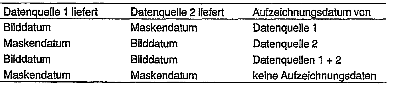
Die Erfindung ist nicht auf das beschriebene Ausführungsbeispiel für eine Gravieranlage beschränkt.The invention is not limited to the exemplary embodiment described for an engraving system.
Auf der Abtasttrommel 3 des Abtasters 2 können gleichzeitig mehrere in Umfangsrichtung hintereinander angeordnete Vorlagen mit dem Abtastorgan 6 abgetastet werden. Der Abtaster 2 läßt sich auch mit mehreren Abtastorganen ausrüsten, so daß gleichzeitig mehrere auf der Abtasttrommel 3 in Axialrichtung nebeneinander angeordnete Vorlagen abgetastet werden können. In diesem Falle weist der Abtaster 2 zusätzliche Speicherregister auf, mit denen die Bilddaten der einzelnen Abtastkanäle im Multiplex-Betrieb aus dem Abtaster 2 ausgelesen und der Signalverarbeitungs-Schaltung 12 zugeführt werden. Die erfindungsgemäße selbsttätige Maskierung einer abgetasteten Vorlage durch unterschiedliche Interpretation der Dichtewerte der Vorlage anhand von Strich-Gradationen kann selbstverständlich auch für sich außerhalb der Gravieranlage Anwendung finden. Die dargestellte Gravieranlage arbeitet mit einem einzelnen Gravierorgan. Zur schnelleren Gravur von Druckzylindern ist es in der Praxis üblich, einen Druckzylinder in mehrere Abschnitte (Gravierstränge) zu unterteilen und die einzelnen Gravierstränge eines Druckzylinders gleichzeitig mit jeweils einem Gravierorgan zu gravieren. Auch in diesem Falle ist die Erfindung mit großem Vorteil anwendbar. Eine Gravieranlage mit mehreren Graviersträngen ist in Fig. 6 angedeutet.On the
Fig. 2 zeigt die Verläufe der in der Gradations-Stufe 32 der Gravieranlage nach Fig. 1 abgelegten Strich-Gradationen zur selbsttätigen Maskierung einer im Abtaster 2 abgetasteten Strich-Vorlage.FIG. 2 shows the courses of the line gradations stored in the
In Fig. 2 a ist der spezielle Gradations-Verlauf für Strich-Vorlagen mit positiven Strichelementen dargestellt, wobei unter positiven Strichelementen schwarze Strichelemente (schwarze Schrift) auf hellem Untergrund verstanden werden.2 a shows the special gradation curve for line templates with positive line elements, positive line elements being understood as black line elements (black writing) on a light background.
Die vom Abtaster 2 gebildeten Bilddaten sind die Eingangs-Bilddaten e der Strich-Gradation, die auf der Abszisse aufgetragen sind. Entsprechend der Digitalisierung des vom Abtastorgan 6 gewonnenen Bildsignals in Eingangs-Bilddaten e von 10 Bit-Auflösung durch den A/D-Wandier 8 umfassen die Eingangs-Bilddaten e einen Wertebereich von 0 bis es = 1023, der die in der Strich-Vorlage ausgemessenen Dichtewerte wiedergibt. Abtastorgan 6 und A/D-Wandler 8 des Abtasters 2 sind so geeicht, daß bei Abtastung des Eichpunktes "Schwarz" in der Strich-Vorlage ein Eingangs-Bilddatum von e1 = 16 (Schwarzwert) und bei Abtastung des Eichpunktes "Weiß" ein Eingangs-Bilddatum von e2 = 768 (Weißwert) entstehen. Beim Überfahren der Kontur eines Strichelementes mit der Blende des Abtastorgans 6 "sieht" diese Grauwerte, und die Eingangs-Bilddaten nehmen entsprechend dem jeweiligen Schwarz/Weiß-Anteil in der Blende Werte zwischen e1 = 16 und e2 = 768 an (Graubereich). Dieser an sich zur Aufzeichnung von rein schwarz/weißen Strichelementen nicht erforderliche Graubereich dient im Tiefdruck zur verbesserten Wiedergabe von Konturen an Strichelementen. Wird dagegen der hellere Untergrund der Strich-Vorlage abgetastet, liefert der Abtaster 2 Bilddaten, die größer als es = 768 sind. Den Eingangs-Bilddaten e sind durch die Strich-Gradation bestimmte Ausgangs-Bilddaten a von 8 Bit innerhalb eines Wertebereiches von 0 bis a4 = 255 zugeordnet, die auf der Ordinate aufgetragen sind.The image data formed by the
Der Wertebereich der Eingangs-Bilddaten ist in einen Informations-Bereich 71 von 0 bis e2 = 768 und in einen Masken-Bereich 72 von e2 = 768 bis es = 1023 unterteilt.The value range of the input image data is divided into an
Erfindungsgemäß werden Eingangs-Bilddaten, die in den eingangsseitigen Informations-Bereich 71 fallen, als Gravierinformation (gültige Bilddaten) und Eingangs-Bilddaten, die in den Masken-Bereich 72 fallen, als Maskendaten (ungültige Bilddaten) interpretiert.According to the invention, input image data which fall into the input-
Die Umsetzung der Eingangs-Bilddaten des Informations-Bereiches 71 erfolgt entsprechend der Strich-Gradation in der Weise, daß bei Abtastung des Eichpunktes "Schwarz" das Ausgangs-Bilddatum a1 = 1 und bei Abtastung des Eichpunktes "Weiß" das Ausgangs-Bilddatum a2 = 161 gebildet wird. Dabei wird beim Ausgangs-Bilddatum ai = 1 ein tiefes Näpfchen (Schwarz) und beim Ausgangs-Bilddatum a2 = 161 ein lichtes Näpfchen (Weiß) graviert. Der Zusammenhang zwischen Eingangs-Bilddaten und Ausgangs-Bilddaten wird durch den Verlauf der Gradationskurve zwischen den Eichpunkten bestimmt, der durch die jeweiligen Druckbedingungen festgelegt wird.The input image data of the
Eingangs-Bilddaten, die einen Wert größer als e2 = 768 haben und damit in den Masken-Bereich 72 fallen, werden entsprechend dem speziellen Verlauf der Strich-Gradation ausgangsseitig in das Maskendatum a4 = 255 umgewandelt, das außerhalb des Wertebereiches der Ausgangs-Bilddaten liegt und somit nicht als Gravierinformation interpretiert wird.Input image data that have a value greater than e2 = 768 and thus fall into the
In Fig. 2 b ist der Gradations-Verlauf für Strich-Vorlagen mit negativen Strichelementen dargestellt, wobei unter negativen Strichelementen weiße Strichelemente (weiße Schrift) auf dunklem Untergrund verstanden werden.2 b shows the gradation curve for line templates with negative line elements, negative line elements being understood to mean white line elements (white writing) on a dark background.
Auch bei einer Strich-Vorlage mit negativen Strichelementen entstehen bei Abtastung des Eichpunktes "Schwarz" das EingangsBilddatum e1 = 16, bei Abtastung des Eichpunktes "Weiß" das Eingangs-Bilddatum e2 =768 und bei Abtastung der weißen Strichelemente Eingangs-Bilddaten, die größer als e2 = 768 sind. In diesem Falle ist der Wertebereich der Eingangs-Bilddaten e in einen Informations-Bereich 71 von ei = 16 bis es = 1023 und in einen außerhalb des Informations-Bereiches 71 liegenden Masken-Bereich 72 von 0 bis ei = 16 unterteilt.Even with a line template with negative line elements, when the calibration point "black" is scanned, the input image data e 1 = 16, when the calibration point "white" is scanned, the input image data e2 = 768 and when the white line elements are scanned, input image data are larger than e2 = 768. In this case, the value range of the input image data e is divided into an
Erfindungsgemäß werden nun alle Dichtewerte der Strich-Vorlage, die größer als der Dichtewert des Eichpunktes "Schwarz" sind, als Vorlagenuntergrund interpretiert und die entsprechenden Eingangs-Bilddaten des Masken-Bereiches 72 durch die Strich-Gradation in das Maskendatum a4 = 255 umgesetzt, während alle in den Informations-Bereich 71 fallenden Eingangs-Bilddaten dem Verlauf der Strich-Gradation nach in gültige Bilddaten des ausgangsseitigen Wertebereiches von a1 = 1 bis as = 254 umgewandelt werden.According to the invention, all density values of the stroke template which are greater than the density value of the calibration point "black" are now interpreted as the template background and the corresponding input image data of the
In Fig. 2 c ist der Gradationsverlauf für Strich-Vorlagen mit gemischt positiven/negativen Strichelementen dargestellt.2 c shows the gradation curve for line templates with mixed positive / negative line elements.
Erfindungsgemäß wird nun ein mittlerer Dichtebereich der Strich-Vorlage zwischen den Dichtewerten des Eichpunktes "Schwarz" und des Eichpunktes "Weiß" als Vorlagenuntergrund interpretiert. Der Masken-Bereich 72 liegt damit innerhalb des ursprünglichen, zur besseren Konturenwiedergabe vorgesehenen Teils des Informations-Bereiches 71 der Strich-Gradationen für positive oder für negative Strichelemente. Dadurch wird der eingangsseitige Wertebereich in einen eingeschränkten Informations-Teilbereich 71' für positive Strichelemente von 0 bis e2 = 300, in den Masken-Bereich 72 von e2 = 300 bis es = 500 und in einen eingeschränkten Informations-Teilbereich 71" für negative Strichelemente von es = 500 bis es = 1023 unterteilt. Der Dichteumfang des Masken-Bereiches 72 wird so festgelegt, daß alle Dichteschwankungen des Vorlagenuntergrundes in den Masken-Bereich 72 fallen. Ebenso wird der verfügbare ausgangsseitige Wertebereich von a1 = 1 bis a5 = 254 in einen ersten, eingeschränkten Teilbereich von a1 = 1 bis as = 127 für positive Strichelemente und in einen zweiten, eingeschränkten Teilbereich für negative Strichelemente von as = 120 bis a5 = 254 unterteilt. Diese Teilbereiche können gleich oder ungleich sein.According to the invention, an average density range of the stroke template between the density values of the calibration point "black" and the calibration point "white" is now interpreted as the template background. The
Eingangs-Bilddaten, die in den Informations-Teilbereich 71' von 0 bis e2 = 300 fallen, werden als gültige Bilddaten für positive Strichelemente gewertet und durch die Strich-Gradation in entsprechende Ausgangs-Bilddaten für positive Strichelemente von a1 = 1 bis a2 = 80 umgesetzt. Eingangs-Bilddaten, die in dem Masken-Bereich 72 von e2 = 300 bis es = 500 liegen, werden durch die Strich-Gradation in das Maskendatum a6 = 255 umcodiert. Eingangs-Bilddaten, die in den Informations-Teilbereich 71" von es = 500 bis es = 1023 fallen, werden durch die Strich-Gradation in Ausgangs-Bilddaten von as = 127 bis a5 = 254 umgesetzt.Input image data which fall in the information subarea 71 'from 0 to e2 = 300 are evaluated as valid image data for positive line elements and by the line gradation into corresponding output image data for positive line elements from a 1 = 1 to a 2 = 80 implemented. Input image data which lie in the
Da bei der Strich-Gradation für gemischt positive/negative Strichelemente der Teilbereich der Ausgangs-Bilddaten für positive Strichelemente von a1 = 1 bis as = 127 gegenüber dem ursprünglichen Wertebereich von a1 = 1 bis as = 254 eingeschränkt und der entsprechende Teilbereich der Ausgangs- Bilddaten für negative Strichelemente von as = 128 bis as = 254 ebenfalls eingeschränkt und zusätzlich noch verschoben ist, muß die Einschränkung und die Verschiebung vor der Weiterverarbeitung der Bilddaten wieder rückgängig gemacht werden. Dazu ist in der Gravieranlage der Fig. 1 zwischen der Bildlinien-Speichereinrichtung 34 und der Verknüpfungs-Stufe 51 eine Decodier-Stufe 75 vorgesehen, die in Fig. 1 nur. gestrichelt angedeutet ist, da sie nur im Falle der Strich-Gradation für gemischt positive/negative Strichelemente wirksam ist. Die Decodier-Stufe 75 enthält entsprechende Korrektur-Gradationen, die auch in die Verknüpfungs-Stufe 51 einprogrammiert sein können. Mit Hilfe der Korrektur-Gradation für positive Strichelemente werden zum Beispiel das Bilddatum a2 = 80 in das ursprüngliche Bilddatum a2 = 161 und das Bilddatum as = 127 in das ursprüngliche Bilddatum as = 254 sowie mit Hilfe der Korrektur-Gradation für negative Strichelemente das Bilddatum as = 127 in das ursprüngliche Bilddatum a1 = 1 und das Bilddatum a4 = 207 in das ursprüngliche Bilddatum a2 = 161 umcodiert.Because the line gradation for mixed positive / negative line elements restricts the sub-range of the output image data for positive line elements from a 1 = 1 to as = 127 compared to the original value range from a 1 = 1 to a s = 254 and the corresponding sub-range of Output image data for negative line elements from as = 128 to as = 254 is also restricted and additionally shifted, the restriction and the shift must be reversed before further processing of the image data. For this purpose, a
Die in der Beschreibung der Fig. 2 genannten Werte sind selbstverständlich nur Beispiele, auf die die Erfindung nicht beschränkt ist.The values mentioned in the description of FIG. 2 are of course only examples to which the invention is not restricted.
Fig. 3 zeigt ein Schema für den Schalt-Betrieb der Gravieranlage, an dem diese Funktion noch einmal erläutert werden soll. In a) sind drei hintereinanderliegende Druckseiten A, B und C dargestellt, deren Bilddaten in der Speichereinrichtung 1 abgelegt sind. In b) ist eine aktuelle Druckseite D angedeutet, deren Bilddaten durch Abtastung der entsprechenden Druckseiten-Vorlagen im Abtaster 2 gewonnen werden. Bei der Gravur soll die aktuelle Druckseite D, die im Datenbestand der Speichereinrichtung 1 enthaltene Druckseite B ersetzen, so daß auf der Aufzeichnungsfläche 77 des Druckzylinders 17 die hintereinander liegenden Druckseiten A, D und C zu gravieren sind, wie dies in c) angedeutet ist. Das zugehörige Quellen-Zuordnungsschema für die Speichereinrichtung 1, das in dem Zuordnungs-Steuerwerk 36 abgelegt ist, ist in d) bzw. e) dargestellt. Das entsprechende Quellen-Zuordnungsschema für den Abtaster 2, das in dem Zuordnungs-Steuerwerk 41 einprogrammiert ist, ist in f) bzw. g) angegeben. In den Quellen-Zuordnungsschemata sind den Druckseiten entsprechende Teilflächen 76 zugeordnet. Die Buchstaben in den Teilflächen 76 sollen angeben, daß die betreffenden Druckseiten graviert werden sollen, während die durchkreuzten Teilflächen 76 besagen, daß die zugehörigen Druckseiten bei der Gravur unberücksichtigt bleiben sollen. In h) ist eine aus den gültigen Bilddaten der Speichereinrichtung 1 für die Druckseiten A und C und aus Maskendaten X gebildeten Bildlinie dargestellt, die in der Bildlinien-Speichereinrichtung 28 der Gravieranlage abgelegt ist. Die Darstellung j) zeigt eine aus den gültigen Bilddaten des Abtasters 2 für die Druckseite D und ebenfalls aus Maskendaten X zusammengesetzte Bildlinie, die in der Bildlinien-Speichereinrichtung 34 zwischengespeichert ist. Die Reihenfolge von Bilddaten und Maskendaten in jeder Bildlinie wird durch das zugehörige Quellen-Zuordnungsschema e) bzw. g) bestimmt. Bild- und Maskendaten beider Bildlinien gelangen an die Verknüpfungs-Stufe 51 der Gravieranlage. Wie bereits erläutert, werden im Schalt-Betrieb jeweils nur die gültigen Bilddaten durch die Verknüpfungs-Stufe 51 als Aufzeichnungsdaten weitergeleitet, so daß die in j) dargestellte Bildlinie auf dem Druckzylinder 17 graviert wird.Fig. 3 shows a diagram for the switching operation of the engraving system, on which this function will be explained again. In a) three successive printed pages A, B and C are shown, the image data of which are stored in the
Fig. 4 zeigt das entsprechende Schema fur den Überlagerungs-Betrieb der Gravieranlage. In a) sind wiederum die hintereinander liegenden Druckseiten A, B und C dargestellt, deren Bilddaten in der Speichereinrichtung 1 abgelegt sind. In b) ist eine Strich-Vorlage 78 mit einer aktuellen Schrift E angedeutet. Die Bilddaten der Strich-Vorlage 78 werden mit Hilfe des Abtasters 2 gewonnen. Bei der Gravur soll die aktuelle Schrift E der Strich-Vorlage 78, die nicht im Datenbestand der Speichereinrichtung 1 enthalten ist, in den Hintergrund der Druckseite A einkopiert werden, während die Druckseiten B und C unverändert graviert werden sollen. Die Anordnung der zu gravierenden Druckseiten A, B und C auf dem Druckzylinder 17 ist in c) dargestellt, wobei auf der Druckseite A durch "A" ein reiner Hintergrundbereich und durch "A+E" ein Überlagerungsbereich für Hintergrund und Schrift symbolisiert werden soll. Das Quellen-Zuordnungsschema für die Speichereinrichtung 1 ist wiederum in d) bzw. e) und das betreffende Quellen-Zuordnungsschema für den Abtaster 2 in f) bzw. g) dargestellt. In h) ist eine aus den in der Speichereinrichtung 1 abgelegten Bilddaten A, B und C der Druckseiten A, B und C gebildete Bildlinie dargestellt, die in der Bildlinien-Speichereinrichtung 28 zwischengespeichert ist. Die Darstellung i) zeigt eine aus den vom Abtaster 2 gewonnenen Bilddaten E für die Schrift E der Strich-Vorlage 78 und aus Maskendaten X zusammengestellte Bildlinie, die in der Bildlinien-Speichereinrichtung 34 abgelegt ist. Der Unterschied zur Maskendaten-Erzeugung bei dem zuvor erläuterten Schalt-Betrieb besteht nun darin, daß lediglich die Maskendaten 79 durch das Quellen-Zuordnungsschema des Abtasters 2 erzeugt werden, während die Maskendaten 80 innerhalb der Strich-Vorlage 78 mit Hilfe der erfindungsgemäße Strich-Gradation entstehen. Schließlich zeigt j) noch die zugehörige gravierte Bildlinie für die Druckseiten-Anordnung nach c).Fig. 4 shows the corresponding scheme for the overlay operation of the engraving system. In a) the successive printed pages A, B and C are again shown, the image data of which are stored in the
Fig. 5 zeigt eine grafische Darstellung, anhand der die Vorteile der freien Zuordnung von Aufzeichnungsdaten zu den Eingangs-Adressen der Verknüpfungs-Stufe 51 beispielsweise beim Einkopieren von Strichelementen, insbesonderen von Schriften, in den Hintergrund einer Druckseite erläutert werden sollen. In Fig. 5 a ist eine den Hintergrund bildende Druckseite 81 dargestellt, in den ein Strichelement 82 einer Strich-Vorlage einkopiert werden soll. Die Linie 83 deutet die Richtung einer zu gravierenden Bildlinie bzw. die Gravierrichtung an.FIG. 5 shows a graphical representation, on the basis of which the advantages of the free assignment of recording data to the input addresses of the
Das in Fig. 5 b dargestellte Diagramm zeigt den Verlauf der von der Speichereinrichtung 1 gelieferten Bildsignalwerte a für den Hintergrund der Druckseite 81 mit konstanter Dichte, aufgetragen über der Bildlinie 83 bzw. über der Zeit t. Das Diagramm in Fig. 5 c zeigt den Verlauf der durch Abtastung der Strich-Vorlage gewonnenen Bildsignalwerte b über der Entsprechenden Bildlinie 83, wobei sich der Verlauf 84 bei Abtastung des Vorlagenuntergrundes, der Verlauf 85 bei Abtastung der Kontur des Strichelementes 82 und der Verlauf 86 bei Abtastung des Strichelementes 82 selbst ergibt. Die gestrichelte Linie soll die Masken-Schwelle der Strich-Gradation andeuten, wobei bei unterhalb der Masken-Schwelle liegenden Bildsignalwerten b die Aufzeichnungssignalwerte c den Bildsignalwerten a entsprechen und bei oberhalb der Masken-Schwelle liegenden Bildsignalwerten b die Aufzeichnungssignalwerte c aus einer Verknüpfung der Bildsignalwerte a und b gebildet werden. Aus den Bildsignalwerten a und b der Speichereinrichtung 1 und des Abtasters 2 werden die Eingangs-Adressen der Verknüpfungs-Stufe 51 gebildet unter denen jeweils zugeordnete Aufzeichnungssignalwerte c abgelegt sind. Dabei läßt sich die Zuordnung von Aufzeichnungssignalwerten c und Eingangs-Adressen in der Verknüpfungs-Stufe 51 so treffen, daß in vorteilhafter Weise jeder gewünschte Übergang vom Hintergrund auf das Strichelement und umgekehrt erzeugt werden kann, wodurch die Reproduktionsqualität erheblich gesteigert wird. Das Diagramm der Fig. 5 d, in dem entsprechend gewählte Aufzeichnungssignalwerte c über der Bildlinie 83 aufgetragen sind, zeigt verschiedene Möglichkeiten für Übergänge an einem Strichelement 82. Durch den Verlauf 87 läßt sich beispielsweise eine Schrift auf einem Untergrund betonen, während durch den Verlauf 88 weichere Übergänge erzielt werden. In vorteilhafter Weise werden insbesondere störende Säume an Konturen vermieden, die beim herkömmlichen Einkopieren mit Hilfe von Steuermasken auftreten. Fig. 5 e zeigt als Stand der Technik das Ergebnis beim Einkopieren mit einer Steuermaske, welche das Bildsignal 89 des Hintergrundes und das Bildsignal 90 eines einzukopierenden Strichelements bei einer bestimmten Schwelle 91 umschaltet. In diesem Falle entstehen an den Konturen des einkopierten Strichelementes störende Säume 92.The diagram shown in FIG. 5 b shows the course of the image signal values a supplied by the
Fig. 6 zeigt eine Weiterbildung der Gravieranlage nach Fig. 1, mit der gleichzeitig mehrere Gravierstränge, im dargestellten Beispiel drei Gravierstränge 94 auf dem Druckzylinder 17 graviert werden können. Die Gravieranlage weist in diesem Falle drei separate Gravierkanäle I, II und III für die drei Gravierstränge 94 auf. Jeder Signalweg 25 bzw. 29 ist gegenüber dem Ausführungsbeispiel in Fig. 1 entsprechend der zusätzlichen Anzahl von zwei Graviersträngen um zwei Masken-Register 27' und 27" bzw. 33' und 33" und um zwei Bildlinien-Speichereinrichtungen 28' und 28" bzw. 34' und 34" erweitert.FIG. 6 shows a development of the engraving system according to FIG. 1, with which several engraving strands, in the example shown three
Jedem Gravierkanal I, II und III ist ein Masken-Register 27, 27' bzw. 27" und eine Bildlinien-Speichereinrichtung 28, 28' bzw. 28" des Signalweges 25 sowie ein entsprechendes Masken-Register 33, 33' bzw. 33" und eine entsprechende Bildlinien-Speichereinrichtung 34, 34' bzw. 34" des Signalweges 29 zugeordnet. Jeder Gravierkanal I, II und III weist ferner eine Verknüpfungs-Stufe 51, 51' bzw. 51", einen D/A-Wandier 14, 14' bzw. 14", einen Gravierverstärker 15, 15' bzw. 15" und ein Gravierorgan 16, 16' bzw. 16" auf.Each engraving channel I, II and III has a
Die in den Zuordnungs-Steuerwerken 36 und 41 abgelegten Quellen-Zuordnungsschemata sind auf die betreffende Anzahl von Graviersträngen erweitert und legen zusätzlich fest, in welchem Gravierstrang oder in welchen Graviersträngen die Druckseiten graviert werden sollen.The source assignment schemes stored in the
Die Speichereinrichtung 1 enthält nunmehr die Bilddaten für sämtliche Gravierstränge. Zur Verteilung der aus der Speichereinrichtung 1 ausgelesenen Bilddaten auf die Gravierkanäle I, II und 111 des Signalweges 25 ist eine Verteiler-Stufe 95 vorgesehen, die von dem Zuordnungs-Steuerwerk 36 über eine Leitung 96 in Abhängigkeit des dort abgelegten Quellen-Zuordnungsschemas gesteuert wird. Ebenso ist eine Verteiler-Stufe 97 für den Signalweg 29 vorgesehen, mit der die vom Abtaster 2 gelieferten Bilddaten auf die Gravierkanäle I, 11 und 111 verteilt werden. Die Verteiler-Stufe 97 wird über eine Leitung 98 vom Zuordnungs-Steuerwerk 41 in Abhängigkeit des dort gespeicherten Quellen-Zuordnungs-Schemas umgeschaltet.The
Das erfindungsgemäße Verfahren ermöglicht in vorteilhafter Weise eine universelle Betriebsweise der Gravieranlage. Bei der Gravur können beispielsweise in auswählbaren Graviersträngen Druckseiten durch aktuelle Druckseiten ersetzt bzw. aktuelle Druckseiten ergänzt werden, während sich in denselben Graviersträngen oder in anderen ausgewählten Graviersträngen gleichzeitig Schriften in Druckseiten einkopieren lassen.The method according to the invention advantageously enables universal operation of the engraving system. With engraving, for example, print pages in selectable engraving lines can be replaced by current printing pages or current printing pages can be supplemented, while fonts can be simultaneously copied into printing pages in the same engraving lines or in other selected engraving lines.
Claims (28)
Priority Applications (7)
| Application Number | Priority Date | Filing Date | Title |
|---|---|---|---|
| AT86105990T ATE54524T1 (en) | 1986-04-30 | 1986-04-30 | METHOD OF RECORDING PRINT FORMS. |
| DE8686105990T DE3672609D1 (en) | 1986-04-30 | 1986-04-30 | METHOD FOR RECORDING PRINTING FORMS. |
| EP86105990A EP0243523B1 (en) | 1986-04-30 | 1986-04-30 | Method of recording printing forms |
| US07/044,015 US4729037A (en) | 1986-04-30 | 1987-04-29 | Method for recording printing forms |
| CN87103147.7A CN1009522B (en) | 1986-04-30 | 1987-04-30 | Recording method of printing plate |
| JP10489487A JPH073997B2 (en) | 1986-04-30 | 1987-04-30 | Original recording method and device |
| CA000536054A CA1267466A (en) | 1986-04-30 | 1987-04-30 | Method for recording printing forms |
Applications Claiming Priority (1)
| Application Number | Priority Date | Filing Date | Title |
|---|---|---|---|
| EP86105990A EP0243523B1 (en) | 1986-04-30 | 1986-04-30 | Method of recording printing forms |
Publications (2)
| Publication Number | Publication Date |
|---|---|
| EP0243523A1 EP0243523A1 (en) | 1987-11-04 |
| EP0243523B1 true EP0243523B1 (en) | 1990-07-11 |
Family
ID=8195100
Family Applications (1)
| Application Number | Title | Priority Date | Filing Date |
|---|---|---|---|
| EP86105990A Expired - Lifetime EP0243523B1 (en) | 1986-04-30 | 1986-04-30 | Method of recording printing forms |
Country Status (7)
| Country | Link |
|---|---|
| US (1) | US4729037A (en) |
| EP (1) | EP0243523B1 (en) |
| JP (1) | JPH073997B2 (en) |
| CN (1) | CN1009522B (en) |
| AT (1) | ATE54524T1 (en) |
| CA (1) | CA1267466A (en) |
| DE (1) | DE3672609D1 (en) |
Families Citing this family (16)
| Publication number | Priority date | Publication date | Assignee | Title |
|---|---|---|---|---|
| JP2703914B2 (en) * | 1988-01-19 | 1998-01-26 | キヤノン株式会社 | Document image processing device |
| IL98700A (en) * | 1990-07-13 | 1994-04-12 | Minnesota Mining & Mfg | Apparatus and method for assembling a composite image from a plurality of data types |
| US5691818A (en) * | 1993-02-25 | 1997-11-25 | Ohio Electronic Engravers, Inc. | System and method for enhancing edges and the like for engraving |
| EP0741485A1 (en) * | 1995-05-05 | 1996-11-06 | Agfa-Gevaert N.V. | Generation of halftoned overlays for combination with halftoned images |
| US6327599B1 (en) | 1995-06-07 | 2001-12-04 | R. R. Donnelley & Sons Company | Apparatus for controlling an electronic press to print fixed and variable information |
| US6332149B1 (en) | 1995-06-07 | 2001-12-18 | R. R. Donnelley & Sons | Imposition process and apparatus for variable imaging system |
| US6952801B2 (en) | 1995-06-07 | 2005-10-04 | R.R. Donnelley | Book assembly process and apparatus for variable imaging system |
| JP3283534B2 (en) * | 1997-06-02 | 2002-05-20 | ハイデルベルガー ドルツクマシーネン アクチエンゲゼルシヤフト | How to engrave an impression cylinder |
| US6246993B1 (en) | 1997-10-29 | 2001-06-12 | R. R. Donnelly & Sons Company | Reorder system for use with an electronic printing press |
| US6205452B1 (en) | 1997-10-29 | 2001-03-20 | R. R. Donnelley & Sons Company | Method of reproducing variable graphics in a variable imaging system |
| US6088710A (en) * | 1997-10-29 | 2000-07-11 | R.R. Donnelley & Sons Company | Apparatus and method for producing fulfillment pieces on demand in a variable imaging system |
| DE19805179B4 (en) * | 1998-02-10 | 2005-03-10 | Hell Gravure Systems Gmbh | Method for engraving printing forms |
| DE19840926B4 (en) * | 1998-09-08 | 2013-07-11 | Hell Gravure Systems Gmbh & Co. Kg | Arrangement for material processing by means of laser beams and their use |
| US7278094B1 (en) | 2000-05-03 | 2007-10-02 | R. R. Donnelley & Sons Co. | Variable text processing for an electronic press |
| US20060279793A1 (en) * | 2004-07-30 | 2006-12-14 | Hell Gravure Systems Gmbh | Printing form processing with a plurality of engraving tool tracks forming lines |
| CN106864007B (en) * | 2017-02-14 | 2022-09-30 | 北京黎马敦太平洋包装有限公司 | Gravure product printing method, gravure plate and single gravure machine |
Citations (1)
| Publication number | Priority date | Publication date | Assignee | Title |
|---|---|---|---|---|
| DE2708421C2 (en) * | 1977-02-26 | 1982-01-14 | Dr.-Ing. Rudolf Hell Gmbh, 2300 Kiel | Method for mixing signals in the production of printing formes |
Family Cites Families (19)
| Publication number | Priority date | Publication date | Assignee | Title |
|---|---|---|---|---|
| US4034400A (en) * | 1970-09-23 | 1977-07-05 | International Publishing Corporation Ltd. | Apparatus for reproducing graphic material |
| US3904816A (en) * | 1971-07-28 | 1975-09-09 | Hell Rudolf | Method for the dot-by-dot and line-by-line reproduction of picture originals |
| NL167897C (en) * | 1975-02-28 | 1982-02-16 | Hell Rudolf Dr Ing Gmbh | APPARATUS FOR MANUFACTURING GRID PRINTING ACCORDING TO AN IMAGE ORIGINAL. |
| GB1582954A (en) * | 1976-06-28 | 1981-01-21 | Crosfield Electronics Ltd | Printing methods and apparatus |
| JPS6019706B2 (en) * | 1977-02-07 | 1985-05-17 | 株式会社リコー | Buffer device that outputs serial image signal input in parallel |
| DE2720944A1 (en) * | 1977-05-10 | 1978-11-16 | Hell Rudolf Dr Ing Gmbh | METHOD AND EQUIPMENT FOR PRODUCING IMAGE COMBINATIONS |
| US4255761A (en) * | 1978-02-21 | 1981-03-10 | Rudolf Hell Gmbh. | Apparatus for mixing image signals to obtain a printing master |
| US4403249A (en) * | 1978-02-21 | 1983-09-06 | Dr. Ing. Rudolf Hell Gmbh. | Apparatus for mixing image signals to obtain a printing master |
| JPS5571353A (en) * | 1978-11-24 | 1980-05-29 | Ricoh Co Ltd | Picture noise eliminating method |
| JPS5655948A (en) * | 1979-10-12 | 1981-05-16 | Dainippon Screen Mfg Co Ltd | Image collecting method in image scanning recorder |
| US4439790A (en) * | 1981-01-23 | 1984-03-27 | Canon Kabushiki Kaisha | Image forming apparatus |
| JPS57150274A (en) * | 1981-03-13 | 1982-09-17 | Fuji Xerox Co Ltd | Image output device |
| JPS5811941A (en) * | 1981-07-16 | 1983-01-22 | Dainippon Screen Mfg Co Ltd | Processing method for picture pattern and character signals in mesh board picture recording device |
| DE3139483C2 (en) * | 1981-10-03 | 1985-06-13 | Dr.-Ing. Rudolf Hell Gmbh, 2300 Kiel | Method and circuit arrangement for increasing contrast |
| JPS5897767A (en) * | 1981-12-07 | 1983-06-10 | Fuji Xerox Co Ltd | Method and device for control of picture processing magnetic disk |
| JPS58157255A (en) * | 1982-03-13 | 1983-09-19 | Dainippon Screen Mfg Co Ltd | Scanning and recording method of picture |
| JPS5964846A (en) * | 1982-10-05 | 1984-04-12 | Dainippon Screen Mfg Co Ltd | Method for simultaneous recording of pattern and line drawing |
| DE3341371C2 (en) * | 1982-11-16 | 1989-09-21 | Dainippon Ink And Chemicals, Inc., Tokio/Tokyo | Method and device for generating a combined image signal |
| JPS6019358A (en) * | 1983-07-14 | 1985-01-31 | Iwatsu Electric Co Ltd | Picture overlay printer |
-
1986
- 1986-04-30 EP EP86105990A patent/EP0243523B1/en not_active Expired - Lifetime
- 1986-04-30 AT AT86105990T patent/ATE54524T1/en not_active IP Right Cessation
- 1986-04-30 DE DE8686105990T patent/DE3672609D1/en not_active Expired - Lifetime
-
1987
- 1987-04-29 US US07/044,015 patent/US4729037A/en not_active Expired - Lifetime
- 1987-04-30 JP JP10489487A patent/JPH073997B2/en not_active Expired - Lifetime
- 1987-04-30 CA CA000536054A patent/CA1267466A/en not_active Expired - Fee Related
- 1987-04-30 CN CN87103147.7A patent/CN1009522B/en not_active Expired
Patent Citations (1)
| Publication number | Priority date | Publication date | Assignee | Title |
|---|---|---|---|---|
| DE2708421C2 (en) * | 1977-02-26 | 1982-01-14 | Dr.-Ing. Rudolf Hell Gmbh, 2300 Kiel | Method for mixing signals in the production of printing formes |
Also Published As
| Publication number | Publication date |
|---|---|
| JPH073997B2 (en) | 1995-01-18 |
| EP0243523A1 (en) | 1987-11-04 |
| CN87103147A (en) | 1988-02-24 |
| JPS62266966A (en) | 1987-11-19 |
| CA1267466A (en) | 1990-04-03 |
| DE3672609D1 (en) | 1990-08-16 |
| CN1009522B (en) | 1990-09-05 |
| US4729037A (en) | 1988-03-01 |
| ATE54524T1 (en) | 1990-07-15 |
Similar Documents
| Publication | Publication Date | Title |
|---|---|---|
| DE2321689C3 (en) | Color scanner | |
| EP0243523B1 (en) | Method of recording printing forms | |
| DE3015337C2 (en) | Method and device for digital color correction of the printing color signals in an image reproduction machine | |
| EP0074422B1 (en) | Method for the production of printing plates by means of printing irregularly distributed points | |
| DE3750860T3 (en) | Method and device for processing color images. | |
| DE3345306C2 (en) | ||
| DE3429568C2 (en) | ||
| DE2708421C2 (en) | Method for mixing signals in the production of printing formes | |
| DE3233427A1 (en) | METHOD FOR CHANGING COLOR REPRODUCTION IN THE IMAGE OF A TEMPLATE REPLIED ON A COLOR PIPE TUBE FOR USE IN MULTI-COLOR PRINTING | |
| EP0123701B1 (en) | Colour picture manufacturing method and apparatus | |
| EP0764310A1 (en) | Method of generating a contonic map | |
| DE19631469C1 (en) | Method and device for performing print jobs | |
| EP0032908B1 (en) | Autotypical analysis process of toning values | |
| EP0033106B1 (en) | Method for improved picture rendition in reproduction technique | |
| DE3637995C2 (en) | Process for converting pixel signals | |
| EP0759248B1 (en) | Process and device for generating a grey composite proof | |
| DE3511705A1 (en) | METHOD FOR SCANNING AN ORIGINAL PICTURE AND ITS IMAGE RECORDING ON A PHOTOELECTRIC WAY | |
| WO1986000770A1 (en) | Method for making impression cylinders for a seamless, respectively endless pattern, by means of block engraving machines | |
| DE3225229C2 (en) | ||
| DD145434A5 (en) | METHOD FOR IMPROVED PLAYING OF LENS ELEMENTS | |
| DE3143962A1 (en) | Image recording method | |
| EP0768795B1 (en) | Method for manufacturing stencil-plates, particularly for paper or textile printing | |
| DE3601269C2 (en) | ||
| EP0036548B1 (en) | Method of engraving printing surfaces | |
| DE10017547B4 (en) | Method of engraving printing cylinders and engraving machine |
Legal Events
| Date | Code | Title | Description |
|---|---|---|---|
| PUAI | Public reference made under article 153(3) epc to a published international application that has entered the european phase |
Free format text: ORIGINAL CODE: 0009012 |
|
| 17P | Request for examination filed |
Effective date: 19870302 |
|
| AK | Designated contracting states |
Kind code of ref document: A1 Designated state(s): AT BE CH DE FR GB IT LI LU NL SE |
|
| D17P | Request for examination filed (deleted) | ||
| R17P | Request for examination filed (corrected) |
Effective date: 19870302 |
|
| RBV | Designated contracting states (corrected) |
Designated state(s): AT BE CH DE FR GB IT LI NL SE |
|
| 17Q | First examination report despatched |
Effective date: 19890509 |
|
| GRAA | (expected) grant |
Free format text: ORIGINAL CODE: 0009210 |
|
| AK | Designated contracting states |
Kind code of ref document: B1 Designated state(s): AT BE CH DE FR GB IT LI NL SE |
|
| PG25 | Lapsed in a contracting state [announced via postgrant information from national office to epo] |
Ref country code: SE Effective date: 19900711 Ref country code: BE Effective date: 19900711 |
|
| REF | Corresponds to: |
Ref document number: 54524 Country of ref document: AT Date of ref document: 19900715 Kind code of ref document: T |
|
| GBT | Gb: translation of ep patent filed (gb section 77(6)(a)/1977) | ||
| REF | Corresponds to: |
Ref document number: 3672609 Country of ref document: DE Date of ref document: 19900816 |
|
| ET | Fr: translation filed | ||
| ITF | It: translation for a ep patent filed | ||
| PLBE | No opposition filed within time limit |
Free format text: ORIGINAL CODE: 0009261 |
|
| STAA | Information on the status of an ep patent application or granted ep patent |
Free format text: STATUS: NO OPPOSITION FILED WITHIN TIME LIMIT |
|
| 26N | No opposition filed | ||
| PGFP | Annual fee paid to national office [announced via postgrant information from national office to epo] |
Ref country code: CH Payment date: 19920317 Year of fee payment: 7 |
|
| PGFP | Annual fee paid to national office [announced via postgrant information from national office to epo] |
Ref country code: AT Payment date: 19920323 Year of fee payment: 7 |
|
| PGFP | Annual fee paid to national office [announced via postgrant information from national office to epo] |
Ref country code: GB Payment date: 19920427 Year of fee payment: 7 |
|
| PGFP | Annual fee paid to national office [announced via postgrant information from national office to epo] |
Ref country code: FR Payment date: 19920429 Year of fee payment: 7 |
|
| ITTA | It: last paid annual fee | ||
| PGFP | Annual fee paid to national office [announced via postgrant information from national office to epo] |
Ref country code: NL Payment date: 19920430 Year of fee payment: 7 |
|
| REG | Reference to a national code |
Ref country code: FR Ref legal event code: TP Ref country code: FR Ref legal event code: CA |
|
| PG25 | Lapsed in a contracting state [announced via postgrant information from national office to epo] |
Ref country code: LI Effective date: 19930430 Ref country code: GB Effective date: 19930430 Ref country code: CH Effective date: 19930430 Ref country code: AT Effective date: 19930430 |
|
| PG25 | Lapsed in a contracting state [announced via postgrant information from national office to epo] |
Ref country code: NL Effective date: 19931101 |
|
| NLV4 | Nl: lapsed or anulled due to non-payment of the annual fee | ||
| PG25 | Lapsed in a contracting state [announced via postgrant information from national office to epo] |
Ref country code: FR Effective date: 19931229 |
|
| REG | Reference to a national code |
Ref country code: CH Ref legal event code: PL |
|
| GBPC | Gb: european patent ceased through non-payment of renewal fee |
Effective date: 19930430 |
|
| REG | Reference to a national code |
Ref country code: FR Ref legal event code: ST |
|
| PGFP | Annual fee paid to national office [announced via postgrant information from national office to epo] |
Ref country code: DE Payment date: 20000427 Year of fee payment: 15 |
|
| PG25 | Lapsed in a contracting state [announced via postgrant information from national office to epo] |
Ref country code: DE Free format text: LAPSE BECAUSE OF NON-PAYMENT OF DUE FEES Effective date: 20020201 |
|
| PG25 | Lapsed in a contracting state [announced via postgrant information from national office to epo] |
Ref country code: IT Free format text: LAPSE BECAUSE OF NON-PAYMENT OF DUE FEES;WARNING: LAPSES OF ITALIAN PATENTS WITH EFFECTIVE DATE BEFORE 2007 MAY HAVE OCCURRED AT ANY TIME BEFORE 2007. THE CORRECT EFFECTIVE DATE MAY BE DIFFERENT FROM THE ONE RECORDED. Effective date: 20050430 |