EP0243341B1 - Biopsy device for sampling tissue probes and application of substances in one operation - Google Patents
Biopsy device for sampling tissue probes and application of substances in one operation Download PDFInfo
- Publication number
- EP0243341B1 EP0243341B1 EP19870890076 EP87890076A EP0243341B1 EP 0243341 B1 EP0243341 B1 EP 0243341B1 EP 19870890076 EP19870890076 EP 19870890076 EP 87890076 A EP87890076 A EP 87890076A EP 0243341 B1 EP0243341 B1 EP 0243341B1
- Authority
- EP
- European Patent Office
- Prior art keywords
- biopsy
- channel
- wall
- application
- tube
- Prior art date
- Legal status (The legal status is an assumption and is not a legal conclusion. Google has not performed a legal analysis and makes no representation as to the accuracy of the status listed.)
- Expired - Lifetime
Links
Images
Classifications
-
- A—HUMAN NECESSITIES
- A61—MEDICAL OR VETERINARY SCIENCE; HYGIENE
- A61B—DIAGNOSIS; SURGERY; IDENTIFICATION
- A61B10/00—Other methods or instruments for diagnosis, e.g. instruments for taking a cell sample, for biopsy, for vaccination diagnosis; Sex determination; Ovulation-period determination; Throat striking implements
- A61B10/02—Instruments for taking cell samples or for biopsy
- A61B10/0233—Pointed or sharp biopsy instruments
- A61B10/0283—Pointed or sharp biopsy instruments with vacuum aspiration, e.g. caused by retractable plunger or by connected syringe
-
- A—HUMAN NECESSITIES
- A61—MEDICAL OR VETERINARY SCIENCE; HYGIENE
- A61M—DEVICES FOR INTRODUCING MEDIA INTO, OR ONTO, THE BODY; DEVICES FOR TRANSDUCING BODY MEDIA OR FOR TAKING MEDIA FROM THE BODY; DEVICES FOR PRODUCING OR ENDING SLEEP OR STUPOR
- A61M5/00—Devices for bringing media into the body in a subcutaneous, intra-vascular or intramuscular way; Accessories therefor, e.g. filling or cleaning devices, arm-rests
- A61M5/14—Infusion devices, e.g. infusing by gravity; Blood infusion; Accessories therefor
- A61M5/158—Needles for infusions; Accessories therefor, e.g. for inserting infusion needles, or for holding them on the body
- A61M5/1582—Double lumen needles
-
- A—HUMAN NECESSITIES
- A61—MEDICAL OR VETERINARY SCIENCE; HYGIENE
- A61M—DEVICES FOR INTRODUCING MEDIA INTO, OR ONTO, THE BODY; DEVICES FOR TRANSDUCING BODY MEDIA OR FOR TAKING MEDIA FROM THE BODY; DEVICES FOR PRODUCING OR ENDING SLEEP OR STUPOR
- A61M25/00—Catheters; Hollow probes
- A61M25/0021—Catheters; Hollow probes characterised by the form of the tubing
- A61M25/0023—Catheters; Hollow probes characterised by the form of the tubing by the form of the lumen, e.g. cross-section, variable diameter
- A61M25/0026—Multi-lumen catheters with stationary elements
- A61M25/0032—Multi-lumen catheters with stationary elements characterized by at least one unconventionally shaped lumen, e.g. polygons, ellipsoids, wedges or shapes comprising concave and convex parts
Definitions
- the invention relates to a biopsy device for obtaining tissue samples with a two- or multi-lumen biopsy cannula, which has a biopsy channel with a constant cross-section over its entire length and at least one application channel and which at its proximal end has connection options for a suction device and at least one application device and its front end is provided with a cutting edge, at least one application channel being formed by a tube eccentrically pushed over the wall of the biopsy channel.
- suction biopsy is based on the principle given by Menghini (Menghini, G. 1957: Un effettivo progresso nella tecnica della puntura biopsia del fegato. Rass. Fisiopat. Clin. Ter. 29, 756).
- This is a hollow needle with an average diameter of 1.4 mm with a possible attachment for a syringe with which a negative pressure (suction) is applied after piercing the skin and before the actual organ puncture.
- the organ puncture liver then takes place in a fraction of a second with continued suction.
- the cutting biopsy is in principle carried out with a ground at the front end Cannula.
- the cutting device and lumen of the cannula are protected during the puncture process by a stylet inserted into the cannula lumen, which is removed after the puncture. Only then is a cylindrical piece of tissue cut out of the punctured organ under suction with a rotating, forward-directed movement (eg: Tru-Cut needle, Travenol).
- Cutting biopsies from lung tissue have a relatively high complication rate due to bleeding events and pneumothorax (McEvoy, R.D., Begley, M.D., Antic, R. 1983: Percutaneous Biopsy of Intrapulmonary Mass Lesions. Cancer 51, 2321).
- pneumothorax McEvoy, R.D., Begley, M.D., Antic, R. 1983: Percutaneous Biopsy of Intrapulmonary Mass Lesions. Cancer 51, 2321).
- a double-lumen puncture cannula for follicular puncture as part of extracorporeal fertilization with a larger-lumen suction channel for sucking off the follicle contents and a smaller-lumen rinsing channel for supplying irrigation fluid into the interior of the follicle is described from the older document DE-A - 35 22 782.
- the puncture cannula is designed as a double-walled tube, which consists of two coaxially and firmly fitted tubes.
- the puncture cannula has a sharpened puncture tip with a hollow section, the cutting edge being formed by the outer tube.
- the invention has for its object to provide a biopsy device of the type described in the introduction, with which both the extraction of tissue samples and the application of substances in one operation is possible in the shortest possible time (less than 1 s).
- the cutting edge is formed solely by an acute-angled end of the biopsy channel wall and the cutting edge of the biopsy channel wall protrudes from the tube and the tube end forms an obtuse angle with the biopsy channel wall.
- the biopsy channel wall preferably ends at a right angle to the longitudinal axis of the biopsy channel.
- the biopsy channel wall is advantageously partially flattened in cross section, so that an application channel is formed between the flattened side of the biopsy channel wall and the tube and there is surface contact between the non-flattened side of the biopsy channel wall and the tube.
- a preferred embodiment is characterized in that a two-part contact mechanism is attached to the needle in a manner known per se, the proximal part of which is firmly connected to the cannula and the distal movable part is held in the initial position by a spring, so that after reaching it a predetermined penetration depth of this part is displaced through the body surface in such a way that one or more contacts between the proximal rigid and the distal movable part are closed, which enable the control of an application system depending on the penetration depth and puncture speed, and further by reaching the stop of the distal part moving part to the proximal part the puncture depth is limited.
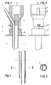
- Fig. 1 shows a longitudinal section
- Fig. 2 shows a cross section along the line II-II of Fig. 1 of the cutting end of a two-channel needle.
- Fig. 3 shows a longitudinal section through a contact mechanism and
- Fig. 4 is a view of the same for 1 and 2 shown two-channel needle.
- the puncture needle has a biopsy channel 1, which also records the largest cross-sectional diameter of the needle. As can be seen from FIG. 1, the separation from the application channel 2 takes place in such a way that there are no corners and edges in the biopsy channel 1 which could impair the quality of the tissue samples. A smaller space of the puncture needle, which is separated from the main channel, functions as the application channel.
- the channels are separated by two thin-walled tubes which are adapted to one another and are eccentrically pushed into one another.
- the cutting end is formed by the biopsy channel 1, which ends at right angles to the longitudinal axis, the wall of which is ground at an acute angle.
- the one through an eccentric over the application channel 2 formed on the tube pushed into the biopsy needle does not extend to the cutting end. Its wall is ground at an obtuse angle, so that a smooth transition of the outer wall of the biopsy channel 1 into the outer wall of the application channel 2 is effected in the section in which the two channels touch.
- a bolt 7 which does not completely close the lumen of the needle and which prevents the tissue sample from being sucked into the vacuum system which can be connected at 3 (e.g. syringe with locking device).
- 4 shows the possible approach for an application system, the arrangement and design (e.g. cone, thread etc.) of which can be adapted to the respective requirements (e.g. system under pressure).
- the puncture depth is limited and the application system is controlled by a mechanism seated on the needle, consisting of a part 6 fastened to the cannula and having one or more contact points and a movable part 5 having one or more contact points, which is held in the initial position by a spring 8 becomes.
- part 5 After reaching a certain puncture depth, part 5 is moved towards part 6 after contact with the body surface until the stop is reached and the contact is closed.
- the number of arrangement of contact points can be adapted to the requirements for controlling the application system.
- a mechanical system is also conceivable without changing the essence of the invention.
- the puncture is carried out according to the Menghini technique, in which, after piercing the skin, a negative pressure is generated with the aid of a lockable syringe attached to point 3.
- the needle is then further inserted into the tissue (organ) to be punctured. After reaching the stop 5, the needle is withdrawn immediately.
- Substances eg blood coagulation substances, vasoactive pharmaceuticals, cytostatics, antibiotics etc.
- the design enables tissue removal and application of substances coordinated with the puncture procedure in one operation. This greatly reduces the duration of the procedure compared to previously known methods.
- the arrangement of the channels ensures, despite the presence of additional channels, a minimum overall cannula diameter with a constant quality of the tissue sample taken for the histological diagnosis.
- this needle enables the uncomplicated sealing of the puncture channel with coagulation-active substances.
- the indications for punctures can be significantly expanded, which means improved diagnostics and therapy.
Description
Die Erfindung betrifft eine Biopsieeinrichtung zur Gewinnung von Gewebsproben mit einer zwei- oder mehrlumigen Biopsiekanüle, die einen Biopsiekanal mit über seine gesamte Länge konstantem Querschnitt sowie mindestens einen Applikationskanal aufweist und die an ihrem proximalen Ende mit Anschlußmöglichkeiten für eine Saug- sowie mindestens eine Applikationsvorrichtung und an ihrem vorderen Ende mit einer Schneide versehen ist, wobei mindestens ein Applikationskanal durch ein exzentrisch über die Biopsiekanalwand geschobenes Rohr gebildet ist.The invention relates to a biopsy device for obtaining tissue samples with a two- or multi-lumen biopsy cannula, which has a biopsy channel with a constant cross-section over its entire length and at least one application channel and which at its proximal end has connection options for a suction device and at least one application device and its front end is provided with a cutting edge, at least one application channel being formed by a tube eccentrically pushed over the wall of the biopsy channel.
Es ist bekannt, daß zur Entnahme von Gewebsproben aus tierischen und menschlichen Organen verschiedene bioptische Techniken auf dem Prinzip einer Einkanalnadel mit Saugvorrichtung und/oder Schneidvorrichtung, mit und ohne Trokar existieren. Bekannt sind weiters mehrlumige Kanülen und Nadeln (DE-C - 818 246 und DE-A - 26 43 594), die für eine Biopsieentnahme und Substanzapplikation in einem Arbeitsgang allerdings nicht geeignet sind.It is known that there are various bioptical techniques for taking tissue samples from animal and human organs based on the principle of a single-channel needle with suction device and / or cutting device, with and without a trocar. Also known are multi-lumen cannulas and needles (DE-C - 818 246 and DE-A - 26 43 594), which, however, are not suitable for biopsy removal and substance application in one operation.
Zur Saugbiopsie ist zu bemerken: Die bekannteste Saugbiopsietechnik basiert auf dem von Menghini angegebenen Prinzip (Menghini, G. 1957: Un effettivo progresso nella tecnica della puntura biopsia del fegato. Rass. Fisiopat. clin. Ter. 29, 756). Dabei handelt es sich um eine im Durchschnitt 1,4 mm im Durchmesser haltende Hohlnadel mit einer Ansatzmöglichkeit für eine Spritze, mit der nach Durchstechen der Haut und vor der eigentlichen Organpunktion ein negativer Druck (Sog) angelegt wird. Die Organpunktion (Leber) erfolgt dann bei anhaltendem Sog im Bruchteil einer Sekunde.Regarding suction biopsy, it should be noted that the best-known suction biopsy technique is based on the principle given by Menghini (Menghini, G. 1957: Un effettivo progresso nella tecnica della puntura biopsia del fegato. Rass. Fisiopat. Clin. Ter. 29, 756). This is a hollow needle with an average diameter of 1.4 mm with a possible attachment for a syringe with which a negative pressure (suction) is applied after piercing the skin and before the actual organ puncture. The organ puncture (liver) then takes place in a fraction of a second with continued suction.
Zur Schneidbiopsie ist zu bemerken: Die Schneidbiopsie erfolgt im Prinzip mit einer am vorderen Ende zugeschliffenen Kanüle. Schneidvorrichtung und Lumen der Kanüle sind während des Punktionsvorganges durch ein in das Kanülenlumen eingelegtes Stilett geschützt, das nach der Punktion entfernt wird. Erst dann wird aus dem punktierten Organ unter Sogwirkung bei drehender, vorwärts gerichteter Bewegung ein zylindrisches Gewebsstück herausgeschnitten (z.B.: Tru-Cut Nadel, Fa. Travenol).Regarding the cutting biopsy, it should be noted that the cutting biopsy is in principle carried out with a ground at the front end Cannula. The cutting device and lumen of the cannula are protected during the puncture process by a stylet inserted into the cannula lumen, which is removed after the puncture. Only then is a cylindrical piece of tissue cut out of the punctured organ under suction with a rotating, forward-directed movement (eg: Tru-Cut needle, Travenol).
Bei allen derzeit üblichen bioptischen Techniken muß mit Komplikationen gerechnet werden, die von der Art der Punktion (wie dem zu punktierenden Organ und der angewandten Technik) und vom Allgemeinzustand des Patienten abhängen. Die Hauptkomplikationen bei der Saugbiopsie der Leber stellen in erster Linie starke Blutungen, gallige Bauchfellentzündungen und der Pneumothorax dar (Lindner, H. 1967: Grenzen und Gefahren der perkutanen Leberbiopsie mit der Menghini-Nadel. Dtsch. med. Wschr. 39, 1751; Piccinino, F., Sagnelli E., Pasquale, G., Guisti G. 1986: Complications following percutaneous liver biopsy. J. Hepatology 2, 165). Schneidbiopsien vom Lungengewebe weisen eine relativ hohe Komplikationsrate durch Blutungsereignisse und Pneumothorax auf (McEvoy, R.D., Begley, M.D., Antic, R. 1983: Percutaneous Biopsy of Intrapulmonary Mass Lesions. Cancer 51, 2321). Auch für Nierenbiopsien und Biopsien anderer Organe gilt in erster Linie eine schwere Blutung als bedeutendste Komplikation.With all currently common bioptic techniques, complications must be expected, which depend on the type of puncture (such as the organ to be punctured and the technique used) and the general condition of the patient. The main complications of the suction biopsy of the liver are primarily heavy bleeding, bilious peritonitis and pneumothorax (Lindner, H. 1967: Limits and dangers of percutaneous liver biopsy with the Menghini needle. Dtsch. Med. Wschr. 39, 1751; Piccinino , F., Sagnelli E., Pasquale, G., Guisti G. 1986: Complications following percutaneous liver biopsy. J. Hepatology 2, 165). Cutting biopsies from lung tissue have a relatively high complication rate due to bleeding events and pneumothorax (McEvoy, R.D., Begley, M.D., Antic, R. 1983: Percutaneous Biopsy of Intrapulmonary Mass Lesions. Cancer 51, 2321). For kidney biopsies and biopsies of other organs, too, heavy bleeding is the most important complication.
Um diesen Komplikationen zu begegnen, wurde die anschließende Plombierung des Stichkanales mit resorbierbarem Material empfohlen, um insbesondere Blutungskomplikationen hintanzuhalten (Riley, S.A., Irving, H.C., Axon, A.T.R., Ellis, W.R., Lintott, D.J., Losowsky M.S. 1984: Percutaneous liver biopsy with plugging the needle track: a safe method for use in patients with impaired coagulation. Lancet, Aug. 25, 1984, 436). Derartige Techniken setzen aber eine lange Verweildauer der Punktionsnadel im Organ voraus, was insbesondere bei Leberpunktionen eine neuerliche Ursache für Komplikationen darstellt (Thaler, H. 1982: Leberbiopsie, Springer-Verlag, Heidelberg-New York).In order to counter these complications, the subsequent sealing of the puncture channel with resorbable material was recommended, in particular to prevent bleeding complications (Riley, SA, Irving, HC, Axon, ATR, Ellis, WR, Lintott, DJ, Losowsky MS 1984: Percutaneous liver biopsy with plugging the needle track: a safe method for use in patients with impaired coagulation. Lancet, Aug. 25, 1984, 436). Such techniques, however, require the puncture needle to remain in the organ for a long time, which is a new cause for liver punctures in particular Complications (Thaler, H. 1982: liver biopsy, Springer-Verlag, Heidelberg-New York).
Aus dem prioritätsälteren nachveröffentlichten Dokument DE-A - 35 22 782 ist eine doppellumige Punktionskanüle zur Follikelpunktion im Rahmen der extrakorporalen Befruchtung mit einem größerlumigen Saugkanal zum Absaugen des Follikelinhalts und einem kleinerlumigen Spülkanal zum Zuführen von Spülflüssigkeit in das Follikelinnere beschrieben. Die Punktionskanüle ist als doppelwandiges Rohr ausgebildet, welches aus zwei koaxial und fest ineinander gepaßten Rohren besteht. Die Punktionskanüle weist eine angeschärfte Einstichspitze mit Hohlschliff auf, wobei die Schneide vom Außenrohr gebildet ist.A double-lumen puncture cannula for follicular puncture as part of extracorporeal fertilization with a larger-lumen suction channel for sucking off the follicle contents and a smaller-lumen rinsing channel for supplying irrigation fluid into the interior of the follicle is described from the older document DE-A - 35 22 782. The puncture cannula is designed as a double-walled tube, which consists of two coaxially and firmly fitted tubes. The puncture cannula has a sharpened puncture tip with a hollow section, the cutting edge being formed by the outer tube.
Die Erfindung stellt sich die Aufgabe, eine Biopsieeinrichtung der eingangs beschriebenen Art zu schaffen, mit der sowohl die Gewinnung von Gewebsproben als auch die Applikation von Substanzen in einem Arbeitsgang in kürzester Zeit (unter 1 s) möglich ist.The invention has for its object to provide a biopsy device of the type described in the introduction, with which both the extraction of tissue samples and the application of substances in one operation is possible in the shortest possible time (less than 1 s).
Diese Aufgabe wird erfindungsgemäß dadurch gelöst, daß die Schneide alleine von einem spitzwinkelig ausgebildeten Ende der Biopsiekanalwand gebildet ist und die Biopsiekanalwand mit ihrer Schneide aus dem Rohr vorragt und das Rohrende mit der Biopspiekanalwand einen stumpfen Winkel einschließt.This object is achieved in that the cutting edge is formed solely by an acute-angled end of the biopsy channel wall and the cutting edge of the biopsy channel wall protrudes from the tube and the tube end forms an obtuse angle with the biopsy channel wall.
Vorzugsweise endet die Biopsiekanalwand rechtwinkelig zur Längsachse des Biopsiekanales.The biopsy channel wall preferably ends at a right angle to the longitudinal axis of the biopsy channel.
Vorteilhaft ist die Biopsiekanalwand im Querschnitt teilweise abgeflacht, so daß zwischen der abgeflachten Seite der Biopsiekanalwand und dem Rohr ein Applikationskanal gebildet ist und zwischen der nicht abgeflachten Seite der Biopsiekanalwand und dem Rohr ein Flächenkontakt besteht.The biopsy channel wall is advantageously partially flattened in cross section, so that an application channel is formed between the flattened side of the biopsy channel wall and the tube and there is surface contact between the non-flattened side of the biopsy channel wall and the tube.
Eine bevorzugte Ausführungsform ist dadurch gekennzeichnet, daß an der Nadel in an sich bekannter Weise ein zweiteiliger Kontaktmechanismus befestigt ist, wobei dessen proximaler Teil mit der Kanüle in fester Verbindung steht und der distale bewegliche Teil durch eine Feder in Ausgangsstellung gehalten wird, so daß nach Erreichen einer vorbestimmten Einstichtiefe dieser Teil durch die Körperoberfläche so verschoben wird, daß ein oder mehrere Kontakte zwischen dem proximalen starren und dem distalen beweglichen Teil geschlossen werden, die die Steuerung eines Applikationssystems abhängig von der Einstichtiefe und Punktionsgeschwindigkeit ermöglichen, und weiters durch Erreichen des Anschlages des distalen beweglichen Teiles an den proximalen Teil die Punktionstiefe begrenzt wird.A preferred embodiment is characterized in that a two-part contact mechanism is attached to the needle in a manner known per se, the proximal part of which is firmly connected to the cannula and the distal movable part is held in the initial position by a spring, so that after reaching it a predetermined penetration depth of this part is displaced through the body surface in such a way that one or more contacts between the proximal rigid and the distal movable part are closed, which enable the control of an application system depending on the penetration depth and puncture speed, and further by reaching the stop of the distal part moving part to the proximal part the puncture depth is limited.
Ein Ausführungsbeispiel der Biospieeinrichtung ist in der Zeichnung dargestellt. Fig. 1 stellt einen Längsschnitt und Fig. 2 einen Querschnitt nach der Linie II-II der Fig. 1 des schneidenden Endes einer Zweikanalnadel dar. Es zeigen weiters die Fig. 3 einen Längsschnitt durch einen Kontaktmechanismus und Fig. 4 eine Ansicht desselben für die in den Fig. 1 und 2 dargestellte Zweikanalnadel.An embodiment of the biospection device is shown in the drawing. Fig. 1 shows a longitudinal section and Fig. 2 shows a cross section along the line II-II of Fig. 1 of the cutting end of a two-channel needle. Furthermore, Fig. 3 shows a longitudinal section through a contact mechanism and Fig. 4 is a view of the same for 1 and 2 shown two-channel needle.
Die Punktionsnadel weist einen Biopsiekanal 1, der den größten Nadelquerdurchmesser miterfaßt, auf. Wie aus Fig. 1 hervorgeht, erfolgt die Trennung gegenüber dem Applikationskanal 2 derart, daß im Biopsiekanal 1 keine Ecken und Kanten entstehen, die eine Qualitätsbeeinträchtigung der Gewebsproben bewirken könnten. Als Applikationskanal fungiert ein vom Hauptkanal abgetrennter kleinerer Raum der Punktionsnadel. Die Trennung der Kanäle ist durch zwei aneinander angepaßte, exzentrisch ineinander geschobene dünnwandige Rohre bewirkt.The puncture needle has a biopsy channel 1, which also records the largest cross-sectional diameter of the needle. As can be seen from FIG. 1, the separation from the
Das schneidende Ende ist vom rechtwinkelig zur Längsachse endenden Biopsiekanal 1 alleine gebildet, dessen Wand spitzwinkelig geschliffen ist. Der durch ein exzentrisch über die Biopsienadelwand geschobenes Rohr entstandene Applikationskanal 2 reicht nicht bis zum schneidenden Ende. Seine Wand ist am Ende stumpfwinkelig geschliffen, so daß ein fließender Übergang der Außenwand des Biopsiekanales 1 in die Außenwand des Applikationskanales 2 in dem Abschnitt, in dem sich beide Kanäle berühren, bewirkt wird.The cutting end is formed by the biopsy channel 1, which ends at right angles to the longitudinal axis, the wall of which is ground at an acute angle. The one through an eccentric over the
Am Ansatzende der Nadel (Fig. 3, 4) befindet sich ein das Lumen der Nadel nicht vollständig verschließender Bolzen 7, der ein Absaugen der Gewebsprobe in das bei 3 anschließbare Unterdrucksystem (z.B. Spritze mit Arretierung) verhindert. 4 stellt die Ansatzmöglichkeit für ein Applikationssystem dar, dessen Anordnung und Gestaltung (z.B. Konus, Gewinde etc.) an die jeweiligen Erfordernisse (z.B. unter Druck stehendes System) angepaßt werden kann. Die Begrenzung der Punktionstiefe und die Steuerung des Applikationssystems erfolgt durch einen der Nadel aufsitzenden Mechanismus, bestehend aus einem an der Kanüle befestigten und einen oder mehrere Kontaktpunkte aufweisenden Teil 6 und einen oder mehrere Kontaktpunkte aufweisenden beweglichen Teil 5, der durch eine Feder 8 in Ausgangsstellung gehalten wird. Nach Erreichen einer bestimmten Punktionstiefe wird Teil 5 nach Berührung mit der Körperoberfläche in Richtung Teil 6 bewegt, bis der Anschlag erreicht ist und der Kontakt geschlossen wird. Die Zahl der Anordnung von Kontaktpunkten kann den Erfordernissen zur Steuerung des Applikationssystems angepaßt werden. Anstelle des skizzierten elektrischen Steuerungssystems ist auch ein mechanisches System vorstellbar, ohne daß dadurch das Wesen der Erfindung eine Änderung erfährt.At the attachment end of the needle (Fig. 3, 4) there is a
Die Punktion erfolgt nach der Menghini-Technik, bei der nach Durchstechen der Haut ein Unterdruck mit Hilfe einer an der Stelle 3 angesetzten, arretierbaren Spritze erzeugt wird. Anschließend wird die Nadel weiter in das zu punktierende Gewebe (Organ) eingestochen. Nach Erreichen des Anschlages 5 wird die Nadel sofort zurückgezogen. Die Injektion von Substanzen (z.B. Blutgerinnungssubstanzen, vasoaktive Pharmaka, Zytostatika, Antibiotika etc.) wird automatisch durch den Auslösemechanismus nach Erreichen einer vorbestimmbaren Einstichtiefe ausgelöst.The puncture is carried out according to the Menghini technique, in which, after piercing the skin, a negative pressure is generated with the aid of a lockable syringe attached to point 3. The needle is then further inserted into the tissue (organ) to be punctured. After reaching the
Die Konstruktion ermöglicht eine Gewebsentnahme und eine mit dem Punktionsvorgang koordinierte Applikation von Substanzen in einem Arbeitsgang. Dadurch wird im Vergleich zu bisher bekannten Methoden die Eingriffsdauer stark verkürzt. Die Anordnung der Kanäle gewährleistet trotz des Vorhandenseins zusätzlicher Kanäle einen minimalen Kanülengesamtdurchmesser bei gleichbleibender Qualität der für die histologische Befundung entnommenen Gewebsprobe. Diese Nadel ermöglicht u.a. die unkomplizierte Plombierung des Punktionskanales mit gerinnungsaktiven Substanzen. Die Indikationen für Punktionen können dadurch wesentlich erweitert werden, was eine verbesserte Diagnostik und Therapie bedeutet.The design enables tissue removal and application of substances coordinated with the puncture procedure in one operation. This greatly reduces the duration of the procedure compared to previously known methods. The arrangement of the channels ensures, despite the presence of additional channels, a minimum overall cannula diameter with a constant quality of the tissue sample taken for the histological diagnosis. Among other things, this needle enables the uncomplicated sealing of the puncture channel with coagulation-active substances. The indications for punctures can be significantly expanded, which means improved diagnostics and therapy.
Claims (4)
- A biopsy device comprising a two- or multi-lumen biopsy cannula including a biopsy channel (1) having a constant cross section over its total length as well as at least one application channel (2) and which, on its proximal end, is provided with connection facilities to an aspiration means as well as to at least one application means and, on its front end, is provided with a cutting edge, wherein at least one application channel is formed by a tube eccentrically slipped over the wall of the biopsy channel, characterized in that the cutting edge alone is formed by an acute-angularly designed end of the biopsy channel and the wall of the biopsy channel projects out of the tube by its cutting edge and the tube end encloses an obtuse angle with the wall of the biopsy channel.
- A biopsy device according to claim 1, characterized in that the wall of the biopsy channel terminates at a right angle relative to the longitudinal axis of the biopsy channel (1).
- A biopsy device according to claim 1 or 2, characterized in that the wall of the biopsy channel is partially flattened in terms of cross section such that an application channel (2) is formed between the flattended side of the wall of the biopsy channel and the tube and a surface contact prevails between the non-flattened side of the wall of the biopsy channel and the tube.
- A biopsy device according to any one of claims 1 to 3, characterized in that a two-part contacting mechanism is fastened to the needle in a manner known per se, its proximal part (6) being firmly connected with the cannula and the distal, movable part (5) being maintained in the starting position by a spring (8) such that this part (5), after having reached a predetermined puncture depth, is displaced through the surface of the body in a manner that one or several contacts between the proximal, firm part (6) and the distal, movable part (5) are closed, thus enabling the control of an application system as a function of the puncture depth and the puncture speed, and, furthermore, the puncture depth is limited by the distal, movable part (6) striking against the proximal part (6).
Applications Claiming Priority (4)
| Application Number | Priority Date | Filing Date | Title |
|---|---|---|---|
| AT104186A AT384165B (en) | 1986-04-21 | 1986-04-21 | Biopsy device for obtaining tissue samples and for administering substances in a single step |
| AT1041/86 | 1986-04-21 | ||
| AT0091487A AT385890B (en) | 1987-04-13 | 1987-04-13 | BIOPSY DEVICE FOR OBTAINING TEST SAMPLES AND APPLICATION OF SUBSTANCES IN ONE WORKPROCESS |
| AT914/87 | 1987-04-13 |
Publications (3)
| Publication Number | Publication Date |
|---|---|
| EP0243341A2 EP0243341A2 (en) | 1987-10-28 |
| EP0243341A3 EP0243341A3 (en) | 1990-01-17 |
| EP0243341B1 true EP0243341B1 (en) | 1992-11-19 |
Family
ID=25594298
Family Applications (1)
| Application Number | Title | Priority Date | Filing Date |
|---|---|---|---|
| EP19870890076 Expired - Lifetime EP0243341B1 (en) | 1986-04-21 | 1987-04-15 | Biopsy device for sampling tissue probes and application of substances in one operation |
Country Status (3)
| Country | Link |
|---|---|
| EP (1) | EP0243341B1 (en) |
| DE (1) | DE3782679D1 (en) |
| ES (1) | ES2036222T3 (en) |
Families Citing this family (13)
| Publication number | Priority date | Publication date | Assignee | Title |
|---|---|---|---|---|
| AT396548B (en) * | 1990-05-03 | 1993-10-25 | Immuno Ag | BIOPSY DEVICE |
| AT397911B (en) * | 1990-07-04 | 1994-08-25 | Avl Verbrennungskraft Messtech | TWO TUMBLE NEEDLE FOR BODY LIQUIDS |
| US5279572A (en) * | 1991-12-03 | 1994-01-18 | Yasuo Hokama | Indwelling intravenous needle with two blood-backflow passage routes |
| US5325857A (en) * | 1993-07-09 | 1994-07-05 | Hossein Nabai | Skin biopsy device and method |
| US5882316A (en) * | 1996-08-29 | 1999-03-16 | City Of Hope | Minimally invasive biopsy device |
| DE10026303A1 (en) * | 2000-05-26 | 2002-02-07 | Pajunk Gmbh | Biopsy needle has triangular cross section needle improves suction of tissue samples |
| GB0120645D0 (en) | 2001-08-24 | 2001-10-17 | Smiths Group Plc | Medico-surgical devices |
| GB0307350D0 (en) | 2003-03-29 | 2003-05-07 | Smiths Group Plc | Catheters |
| US20090216151A1 (en) * | 2008-02-27 | 2009-08-27 | Speeg Trevor W V | Biopsy Probe With Hypodermic Lumen |
| KR20140070333A (en) * | 2012-11-30 | 2014-06-10 | 국립암센터 | Device for sampling biopsy |
| US10744305B2 (en) * | 2015-10-28 | 2020-08-18 | Becton, Dickinson And Company | Ergonomic IV systems and methods |
| CN109330635B (en) * | 2018-07-27 | 2024-02-06 | 尚华 | Multifunctional intravascular tissue puncture needle and application method thereof |
| CN109171827A (en) * | 2018-10-24 | 2019-01-11 | 杭州丽康医学科技股份有限公司 | A kind of binary channels coaxial sleeve needle |
Family Cites Families (3)
| Publication number | Priority date | Publication date | Assignee | Title |
|---|---|---|---|---|
| DE2643594A1 (en) * | 1975-10-06 | 1977-04-14 | Roger Beelen | HAEMODIALYSIS NEEDLE |
| DE3364080D1 (en) * | 1982-10-29 | 1986-07-17 | Miles Lab | Long indwelling double bore catheter |
| DE3522782A1 (en) * | 1985-06-26 | 1987-01-15 | Peter Brehm Chir Mechanik Werk | Double-lumen follicle-biopsy cannula |
-
1987
- 1987-04-15 EP EP19870890076 patent/EP0243341B1/en not_active Expired - Lifetime
- 1987-04-15 DE DE8787890076T patent/DE3782679D1/en not_active Expired - Lifetime
- 1987-04-15 ES ES87890076T patent/ES2036222T3/en not_active Expired - Lifetime
Also Published As
| Publication number | Publication date |
|---|---|
| EP0243341A3 (en) | 1990-01-17 |
| EP0243341A2 (en) | 1987-10-28 |
| DE3782679D1 (en) | 1992-12-24 |
| ES2036222T3 (en) | 1993-05-16 |
Similar Documents
| Publication | Publication Date | Title |
|---|---|---|
| US4850373A (en) | Biopsy device | |
| EP0263096B1 (en) | Device and method of sampling liquid, tissue | |
| DE2043843C3 (en) | Device for taking samples from internal human and animal organs | |
| DE3917051C2 (en) | ||
| DE69633750T2 (en) | Device for automatic biopsy and soft tissue removal | |
| DE19510455B4 (en) | Surgical instrument for the abrupt insertion of an intraosseous trocar needle | |
| DE2109608C3 (en) | Device for introducing a catheter | |
| DE69838440T2 (en) | Vacuum control system for automatic biopsy device | |
| EP0243341B1 (en) | Biopsy device for sampling tissue probes and application of substances in one operation | |
| DE2605004C3 (en) | Device for drawing blood from a patient and treating the blood with an anticoagulant | |
| DE19909567B4 (en) | Apparatus and method for cutting | |
| EP0465458B1 (en) | Dual lumen needle for withdrawal of body fluids | |
| DE2845643C2 (en) | Catheter connection head with at least one channel in a base body | |
| WO2005013830A1 (en) | Device used for needle biopsy | |
| EP0679408A2 (en) | Device for introduction of a catheter into a body cavity | |
| EP0010321A1 (en) | Device for the single-handed operation of a biopsy instrument | |
| DE19806693A1 (en) | Telescopically working needle and tube system for removal of tumor | |
| EP0221007B1 (en) | Thin-needle biopsy cannule with a mandrel | |
| DE112016000756T5 (en) | Device for generating a local vacuum at a distal end of a sampling device | |
| DE3326648C2 (en) | Balloon catheter | |
| DE19601214A1 (en) | Device for taking blood | |
| WO2001008572A1 (en) | Cannula system for introducing endoscopic tools in a human or animal body | |
| DE2541494A1 (en) | Hypodermic needle blood taking device - has valves at needle end and at attachable evacuated chamber connection | |
| EP3530304A1 (en) | Cannula for intravitreal injection and puncture | |
| EP1206216B1 (en) | Syringe |
Legal Events
| Date | Code | Title | Description |
|---|---|---|---|
| PUAI | Public reference made under article 153(3) epc to a published international application that has entered the european phase |
Free format text: ORIGINAL CODE: 0009012 |
|
| 17P | Request for examination filed |
Effective date: 19870507 |
|
| AK | Designated contracting states |
Kind code of ref document: A2 Designated state(s): BE CH DE ES FR GB GR IT LI LU NL SE |
|
| RAP1 | Party data changed (applicant data changed or rights of an application transferred) |
Owner name: DINGES, HANS PETER, DR. Owner name: IMMUNO AKTIENGESELLSCHAFT FUER CHEMISCH-MEDIZINISC |
|
| RIN1 | Information on inventor provided before grant (corrected) |
Inventor name: DINGES, HANS PETER, DR. Inventor name: ZATLOUKAL, KURT, DR. |
|
| RAP1 | Party data changed (applicant data changed or rights of an application transferred) |
Owner name: IMMUNO AKTIENGESELLSCHAFT FUER CHEMISCH-MEDIZINISC |
|
| PUAL | Search report despatched |
Free format text: ORIGINAL CODE: 0009013 |
|
| AK | Designated contracting states |
Kind code of ref document: A3 Designated state(s): BE CH DE ES FR GB GR IT LI LU NL SE |
|
| RAP1 | Party data changed (applicant data changed or rights of an application transferred) |
Owner name: IMMUNO AKTIENGESELLSCHAFT |
|
| 17Q | First examination report despatched |
Effective date: 19910515 |
|
| GRAA | (expected) grant |
Free format text: ORIGINAL CODE: 0009210 |
|
| AK | Designated contracting states |
Kind code of ref document: B1 Designated state(s): BE CH DE ES FR GB GR IT LI LU NL SE |
|
| PG25 | Lapsed in a contracting state [announced via postgrant information from national office to epo] |
Ref country code: GR Free format text: LAPSE BECAUSE OF FAILURE TO SUBMIT A TRANSLATION OF THE DESCRIPTION OR TO PAY THE FEE WITHIN THE PRESCRIBED TIME-LIMIT Effective date: 19921119 |
|
| REF | Corresponds to: |
Ref document number: 3782679 Country of ref document: DE Date of ref document: 19921224 |
|
| ITF | It: translation for a ep patent filed |
Owner name: SOCIETA' ITALIANA BREVETTI S.P.A. |
|
| ET | Fr: translation filed | ||
| GBT | Gb: translation of ep patent filed (gb section 77(6)(a)/1977) |
Effective date: 19930216 |
|
| PG25 | Lapsed in a contracting state [announced via postgrant information from national office to epo] |
Ref country code: LU Free format text: LAPSE BECAUSE OF NON-PAYMENT OF DUE FEES Effective date: 19930430 |
|
| REG | Reference to a national code |
Ref country code: ES Ref legal event code: FG2A Ref document number: 2036222 Country of ref document: ES Kind code of ref document: T3 |
|
| PLBE | No opposition filed within time limit |
Free format text: ORIGINAL CODE: 0009261 |
|
| STAA | Information on the status of an ep patent application or granted ep patent |
Free format text: STATUS: NO OPPOSITION FILED WITHIN TIME LIMIT |
|
| 26N | No opposition filed | ||
| EAL | Se: european patent in force in sweden |
Ref document number: 87890076.0 |
|
| REG | Reference to a national code |
Ref country code: GB Ref legal event code: IF02 |
|
| PGFP | Annual fee paid to national office [announced via postgrant information from national office to epo] |
Ref country code: FR Payment date: 20060417 Year of fee payment: 20 |
|
| PGFP | Annual fee paid to national office [announced via postgrant information from national office to epo] |
Ref country code: GB Payment date: 20060424 Year of fee payment: 20 |
|
| PGFP | Annual fee paid to national office [announced via postgrant information from national office to epo] |
Ref country code: SE Payment date: 20060426 Year of fee payment: 20 Ref country code: CH Payment date: 20060426 Year of fee payment: 20 |
|
| PGFP | Annual fee paid to national office [announced via postgrant information from national office to epo] |
Ref country code: IT Payment date: 20060430 Year of fee payment: 20 |
|
| PGFP | Annual fee paid to national office [announced via postgrant information from national office to epo] |
Ref country code: BE Payment date: 20060516 Year of fee payment: 20 |
|
| PGFP | Annual fee paid to national office [announced via postgrant information from national office to epo] |
Ref country code: NL Payment date: 20060524 Year of fee payment: 20 |
|
| PGFP | Annual fee paid to national office [announced via postgrant information from national office to epo] |
Ref country code: ES Payment date: 20060526 Year of fee payment: 20 |
|
| PGFP | Annual fee paid to national office [announced via postgrant information from national office to epo] |
Ref country code: DE Payment date: 20060531 Year of fee payment: 20 |
|
| PG25 | Lapsed in a contracting state [announced via postgrant information from national office to epo] |
Ref country code: NL Free format text: LAPSE BECAUSE OF EXPIRATION OF PROTECTION Effective date: 20070415 |
|
| PG25 | Lapsed in a contracting state [announced via postgrant information from national office to epo] |
Ref country code: ES Free format text: LAPSE BECAUSE OF EXPIRATION OF PROTECTION Effective date: 20070416 |
|
| REG | Reference to a national code |
Ref country code: GB Ref legal event code: PE20 |
|
| REG | Reference to a national code |
Ref country code: CH Ref legal event code: PL |
|
| NLV7 | Nl: ceased due to reaching the maximum lifetime of a patent |
Effective date: 20070415 |
|
| EUG | Se: european patent has lapsed | ||
| REG | Reference to a national code |
Ref country code: ES Ref legal event code: FD2A Effective date: 20070416 |
|
| PG25 | Lapsed in a contracting state [announced via postgrant information from national office to epo] |
Ref country code: GB Free format text: LAPSE BECAUSE OF EXPIRATION OF PROTECTION Effective date: 20070414 |
|
| BE20 | Be: patent expired |
Owner name: *IMMUNO A.G. Effective date: 20070415 |