EP0243334A1 - Hydraulic torque impulse generator with bypass means - Google Patents
Hydraulic torque impulse generator with bypass means Download PDFInfo
- Publication number
- EP0243334A1 EP0243334A1 EP87850131A EP87850131A EP0243334A1 EP 0243334 A1 EP0243334 A1 EP 0243334A1 EP 87850131 A EP87850131 A EP 87850131A EP 87850131 A EP87850131 A EP 87850131A EP 0243334 A1 EP0243334 A1 EP 0243334A1
- Authority
- EP
- European Patent Office
- Prior art keywords
- fluid chamber
- drive member
- pressure compartments
- output spindle
- spindle
- Prior art date
- Legal status (The legal status is an assumption and is not a legal conclusion. Google has not performed a legal analysis and makes no representation as to the accuracy of the status listed.)
- Granted
Links
Images

Classifications
-
- B—PERFORMING OPERATIONS; TRANSPORTING
- B25—HAND TOOLS; PORTABLE POWER-DRIVEN TOOLS; MANIPULATORS
- B25B—TOOLS OR BENCH DEVICES NOT OTHERWISE PROVIDED FOR, FOR FASTENING, CONNECTING, DISENGAGING OR HOLDING
- B25B21/00—Portable power-driven screw or nut setting or loosening tools; Attachments for drilling apparatus serving the same purpose
- B25B21/02—Portable power-driven screw or nut setting or loosening tools; Attachments for drilling apparatus serving the same purpose with means for imparting impact to screwdriver blade or nut socket
Definitions
- This invention relates to a hydraulic torque impulse generator of the type comprising a drive member coupled to a rotation motor, a substantially cylindrical fluid chamber confined in said drive member, an output spindle provided with a rear impulse receiving portion which extends into said fluid chamber, and at least two radially slidable vanes carried by said rear spindle portion and arranged to cooperate sealingly with corresponding seal portions on the wall of said fluid chamber, at least two axially extending seal ribs on the fluid chamber wall and at least two axially extending seal ribs on the rear spindle portion arranged to cooperate with said seal ribs on the fluid chamber wall, said vanes, seal portions and seal ribs being arranged to divide said fluid chamber during two or more limited intervals of each revolution of said drive member relative to said output spindle into at least two high pressure compartments and at least two low pressure compartments.
- the main object of the invention is to provide a hydraulic torque impulse generator of the above type with means by which the generation of more than one torque impulse per revolution of the drive member in relation to the output spindle is avoided.
- a torque impulse generator shown in Figs 1-4 10 designates the drive member which via a socket portion 11 in a rear end wall 12 is connectable to a rotation motor.
- the rear end wall 12 is clamped by a ring nut 13 against an annular shoulder 15 in the drive member 10.
- the latter confines a substantially cylindrical fluid chamber 16 into which extends the rear portion 17 of an output spindle 18.
- the output spindle 18 is journalled on one hand in the central opening 19 of the forward end wall 14 of the fluid chamber 16 and on the other hand in a bore 21 in the rear end wall 12.
- the spindle portion 17 is formed with a cylindrical rear extension 20 which is rotatively received in the bore 21.
- the spindle portion 17 is formed with a transverse through slot 22 in which two sliding vanes 23, 24 are supported in a diametrically opposed disposition.
- the vanes 23, 24 are arranged to cooperate sealingly with two diametrically opposed and axially extending seal portions 25, 26 on the fluid chamber wall.
- Such sealing cooperation occurs twice every relative revolution between the drive member 10 and the output spindle 18.
- two diametrically opposed seal ribs 27, 28 on the spindle portion 17 cooperate sealingly with two diametrically opposed seal ribs 29, 30 on the fluid chamber wall.
- the seal ribs 27, 28 on the spindle portion 17 are located at a 90° angular distance from the vanes 23, 24, and the seal ribs 29, 30 on the fluid chamber wall are disposed at a 90° angular distance from the seal portions 25, 26.
- passages 32, 33, 34, 35 which at their one ends are open into the fluid chamber 16. At their opposite ends these passages are open into the bore 21.
- Two of these passages 32, 33 are open to the bore 21 in one common plane III-III transverse to the rotation axis ofthe spindle 18, whereas the other two passages 34, 35 are open to the bore 21 in another transverse plane IV-IV axially spaced from plane III-III.
- the rear spindle extension 20 is formed with an arc-shaped slot 37 by which communication between the passages 32, 33 is controlled.
- the spindle extension 20 has an arc-shaped slot 38 for controlling the communication between passages 34, 35.
- Slot 37 is located at a 180° angular distance from slot 38.
- the drive member 10 is rotated in relation to the output spindle 18, and during two limited intervals of each revolution of the drive member 10 relative to the output spindle 18 there is obtained a sealing cooperation between vanes 23, 24 and seal portions 25, 26 as well as between seal ribs 27, 28 on spindle portion 17 and seal ribs 29, 30 on the drive member 10.
- the fluid chamber 16 is divided into two high pressure compartments H.P. and two low pressure compartments L.P.
- the slot 37 interconnects the passages 33, 34, see Fig 3.
- the slot 38 interconnects the passages 32, 35. This means that the two high pressure compartments H.P. are shortcircuited to the low pressure compartments L.P. and that no pressure peaks are built up in the high pressure compartments H.P. Accordingly, no torque impulse is generated during this sequence.
- a rotated drive member 50 comprises a fluid chamber 51 which is partly defined by a rear end wall 54 and into which a rear portion 52 of an output spindle 53 extends.
- the rear spindle portion 52 has three radial slots 55, 56, 57 which are distributed at equal angular distances and which support three radially slidable vanes 58, 59, 60.
- On the fluid chamber wall there are three seal portions 62, 63, 64 for sealing cooperation with the vanes 58, 59, 60. Since both the vanes and the fluid chamber seal portions are symmetrically located there is obtained a sealing cooperation therebetween during three limited intervals for each revolution of the drive member 50 relative to the output spindle 53.
- the drive member 50 also comprises three symmetrically disposed seal ribs 65, 66, 67 for sealing cooperation with three corresponding seal ribs 68, 69, 70 on the spindle portion 52.
- a concentric rear extension 71 on the output spindle 53 is sealingly rotated in a bore 72 in the rear end wall 54 and comprises a circumferential slot 73 which extends over a major part of the peripheri.
- the slot 73 is interrupted by a land 79.
- a part circular passage 74 in the rear end wall 54 interconnects three openings 75, 76, 77 which communicate with the three high pressure compartments H.P.
- a fourth opening 78 in end wall 54 opens into one of the three low pressure compartments L.P. The opening 78 communicates with the other two low pressure compartments L.P. via the vane slots 55, 56, 57.
- the high pressure compartments H.P. will communicate with the low pressure compartments L.P. via the openings 75, 76, 77, the part circular passage 74, the circumferential slot 73, the opening 78 and the vane slots 55, 56, 57 during two of the three seal intervals.
- the opening 78 blocked by the land 79 and, accordingly, it is out of communication with the slot 73. This means that no bypass is obtained and that a torque impulse is generated in the output spindle 53.
Abstract
Description
- This invention relates to a hydraulic torque impulse generator of the type comprising a drive member coupled to a rotation motor, a substantially cylindrical fluid chamber confined in said drive member, an output spindle provided with a rear impulse receiving portion which extends into said fluid chamber, and at least two radially slidable vanes carried by said rear spindle portion and arranged to cooperate sealingly with corresponding seal portions on the wall of said fluid chamber, at least two axially extending seal ribs on the fluid chamber wall and at least two axially extending seal ribs on the rear spindle portion arranged to cooperate with said seal ribs on the fluid chamber wall, said vanes, seal portions and seal ribs being arranged to divide said fluid chamber during two or more limited intervals of each revolution of said drive member relative to said output spindle into at least two high pressure compartments and at least two low pressure compartments.
- The main object of the invention is to provide a hydraulic torque impulse generator of the above type with means by which the generation of more than one torque impulse per revolution of the drive member in relation to the output spindle is avoided.
- On the drawings:
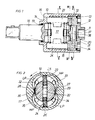
- Fig 1 shows a longitudinal section through an impulse generator according to one embodiment of the invention.
- Fig 2 shows a cross section along line II-II in Fig 1.
- Figs 3 and 4 show cross sections along line III-III in Fig 1 and illustrate different operation sequences.
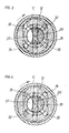
- Fig 5 shows a longitudinal section through an impulse generator according to another embodiment of the invention.
- Fig 6 shows a cross section along line VI-VI in Fig 5.
- In the torque impulse generator shown in Figs 1-4 10 designates the drive member which via a
socket portion 11 in arear end wall 12 is connectable to a rotation motor. Therear end wall 12 is clamped by aring nut 13 against anannular shoulder 15 in thedrive member 10. The latter confines a substantiallycylindrical fluid chamber 16 into which extends therear portion 17 of anoutput spindle 18. Theoutput spindle 18 is journalled on one hand in thecentral opening 19 of theforward end wall 14 of thefluid chamber 16 and on the other hand in abore 21 in therear end wall 12. To this end thespindle portion 17 is formed with a cylindricalrear extension 20 which is rotatively received in thebore 21. - The
spindle portion 17 is formed with a transverse throughslot 22 in which two slidingvanes vanes seal portions drive member 10 and theoutput spindle 18. Simultaneously with this sealing engagement two diametrically opposedseal ribs 27, 28 on thespindle portion 17 cooperate sealingly with two diametrically opposedseal ribs seal ribs 27, 28 on thespindle portion 17 are located at a 90° angular distance from thevanes seal ribs seal portions - In the
rear end wall 12 there are fourpassages fluid chamber 16. At their opposite ends these passages are open into thebore 21. Two of thesepassages bore 21 in one common plane III-III transverse to the rotation axis ofthespindle 18, whereas the other twopassages bore 21 in another transverse plane IV-IV axially spaced from plane III-III. - In the plane IV-IV the
rear spindle extension 20 is formed with an arc-shaped slot 37 by which communication between thepassages spindle extension 20 has an arc-shaped slot 38 for controlling the communication betweenpassages Slot 37 is located at a 180° angular distance fromslot 38. - In operation the
drive member 10 is rotated in relation to theoutput spindle 18, and during two limited intervals of each revolution of thedrive member 10 relative to theoutput spindle 18 there is obtained a sealing cooperation betweenvanes seal portions seal ribs 27, 28 onspindle portion 17 andseal ribs drive member 10. During these two intervals, illustrated in Fig 3 and 4, thefluid chamber 16 is divided into two high pressure compartments H.P. and two low pressure compartments L.P. During one of these intervals theslot 37 interconnects thepassages slot 38 interconnects thepassages - As the
drive member 10 has rotated another 180°, see Fig 4, the seals of the drive member and the output spindle are again effective in dividing thefluid chamber 16 into high and low pressure compartments, H.P. and L.P. respectively. In this position, however, theslots drive member 10, which means that no bypass flow is obtained and that the high pressure compartments H.P. actually are sealed off from the low pressure compartments L.P. Pressure peaks are built up in the high pressure compartments H.P. and a torque impulse is generated in theoutput spindle 18. - In the embodiment shown in Fig 5 and 6 a rotated
drive member 50 comprises afluid chamber 51 which is partly defined by arear end wall 54 and into which arear portion 52 of anoutput spindle 53 extends. Therear spindle portion 52 has threeradial slots slidable vanes seal portions vanes drive member 50 relative to theoutput spindle 53. Thedrive member 50 also comprises three symmetrically disposedseal ribs 65, 66, 67 for sealing cooperation with threecorresponding seal ribs spindle portion 52. - A concentric
rear extension 71 on theoutput spindle 53 is sealingly rotated in abore 72 in therear end wall 54 and comprises acircumferential slot 73 which extends over a major part of the peripheri. Theslot 73 is interrupted by aland 79. - A part
circular passage 74 in therear end wall 54 interconnects threeopenings fourth opening 78 inend wall 54 opens into one of the three low pressure compartments L.P. The opening 78 communicates with the other two low pressure compartments L.P. via thevane slots - At rotation of the
drive member 50 relative to theoutput spindle 53 the high pressure compartments H.P. will communicate with the low pressure compartments L.P. via theopenings circular passage 74, thecircumferential slot 73, the opening 78 and thevane slots opening 78 blocked by theland 79 and, accordingly, it is out of communication with theslot 73. This means that no bypass is obtained and that a torque impulse is generated in theoutput spindle 53.
Claims (3)
characterized in that a first passage means (32-35; 74-78) is located in one of the end walls (12; 54) of said fluid chamber (16; 51), and that a second passage means (37, 38; 73) is located in said output spindle (18; 53), said first and second passage means being arranged to be aligned and form bypass passages between said high pressure compartments (H.P.) and said low pressure compartments (L.P.) during all but one of said limited intervals of each revolution of said drive member (10; 50) relative to said output spindle (18; 53), thereby generating one torque impulse per revolution.
Applications Claiming Priority (2)
| Application Number | Priority Date | Filing Date | Title |
|---|---|---|---|
| SE8601834A SE460713B (en) | 1986-04-22 | 1986-04-22 | HYDRAULIC TORQUE PULSE |
| SE8601834 | 1986-04-22 |
Publications (2)
| Publication Number | Publication Date |
|---|---|
| EP0243334A1 true EP0243334A1 (en) | 1987-10-28 |
| EP0243334B1 EP0243334B1 (en) | 1991-06-26 |
Family
ID=20364286
Family Applications (1)
| Application Number | Title | Priority Date | Filing Date |
|---|---|---|---|
| EP87850131A Expired EP0243334B1 (en) | 1986-04-22 | 1987-04-22 | Hydraulic torque impulse generator with bypass means |
Country Status (5)
| Country | Link |
|---|---|
| US (1) | US4854916A (en) |
| EP (1) | EP0243334B1 (en) |
| JP (1) | JPS63256372A (en) |
| DE (1) | DE3770983D1 (en) |
| SE (1) | SE460713B (en) |
Cited By (7)
| Publication number | Priority date | Publication date | Assignee | Title |
|---|---|---|---|---|
| EP0290411A2 (en) * | 1987-05-08 | 1988-11-09 | Atlas Copco Aktiebolag | Hydraulic torque impulse generator |
| EP0309625A1 (en) * | 1987-09-29 | 1989-04-05 | Nippon Pneumatic Manufacturing Co. Ltd. | Hydraulic pulse wrench |
| EP0521898A1 (en) * | 1990-03-29 | 1993-01-13 | Chicago Pneumatic Tool Company | Adjustable pressure dual piston impulse clutch |
| EP0676260A1 (en) * | 1994-04-08 | 1995-10-11 | Uryu Seisaku Limited | An impulse torque generator for a hydraulic power wrench |
| US8697753B1 (en) | 2013-02-07 | 2014-04-15 | Polichem Sa | Method of treating onychomycosis |
| WO2015097092A1 (en) * | 2013-12-27 | 2015-07-02 | Atlas Copco Industrial Technique Ab | Hydraulic torque impulse generator |
| SE2230372A1 (en) * | 2022-11-17 | 2024-01-09 | Atlas Copco Ind Technique Ab | Power tool comprising a hydraulic pulse unit |
Families Citing this family (7)
| Publication number | Priority date | Publication date | Assignee | Title |
|---|---|---|---|---|
| JPS6327266U (en) * | 1986-07-30 | 1988-02-23 | ||
| JP2779749B2 (en) * | 1993-04-06 | 1998-07-23 | 瓜生製作株式会社 | Impact torque generator for hydraulic torque wrench |
| US5741186A (en) * | 1994-04-08 | 1998-04-21 | Uryu Seisaku, Ltd. | Impulse torque generator for a hydraulic power wrench |
| US6105595A (en) * | 1997-03-07 | 2000-08-22 | Cooper Technologies Co. | Method, system, and apparatus for automatically preventing or allowing flow of a fluid |
| US5890848A (en) * | 1997-08-05 | 1999-04-06 | Cooper Technologies Company | Method and apparatus for simultaneously lubricating a cutting point of a tool and controlling the application rate of the tool to a work piece |
| WO2005099965A1 (en) * | 2004-04-07 | 2005-10-27 | Nippon Pneumatic Manufacturing Co., Ltd. | Pulse wrench |
| US8333143B2 (en) * | 2009-07-31 | 2012-12-18 | Yu-Hui Liao | Hydraulic cylinder device |
Citations (12)
| Publication number | Priority date | Publication date | Assignee | Title |
|---|---|---|---|---|
| US3116617A (en) * | 1961-12-12 | 1964-01-07 | Ingersoll Rand Co | Fluid impulse torque tool |
| US3191404A (en) * | 1963-04-16 | 1965-06-29 | Ingersoll Rand Co | Acceleration control device |
| US3196636A (en) * | 1963-05-15 | 1965-07-27 | Ingersoll Rand Co | Sealing device for power tool |
| US3212294A (en) * | 1962-12-12 | 1965-10-19 | Ingersoll Rand Co | Cam type impulse tool |
| US3214941A (en) * | 1963-09-27 | 1965-11-02 | Thor Power Tool Co | Impulse tool |
| US3221515A (en) * | 1962-12-12 | 1965-12-07 | Ingersoll Rand Co | Gear type impulse tool |
| US3222886A (en) * | 1963-05-02 | 1965-12-14 | Ingersoll Rand Co | Spindle blade |
| US3263449A (en) * | 1963-11-22 | 1966-08-02 | Thor Power Tool Co | Impulse tool |
| FR2032502A1 (en) * | 1969-02-28 | 1970-11-27 | Atlas Copco Ab | |
| GB1331919A (en) * | 1971-11-24 | 1973-09-26 | Gardner Denver Co | Fluid actuated impact wrench |
| GB2136719A (en) * | 1983-03-04 | 1984-09-26 | Uryu Seisaku Ltd | Power driven wrench having hydraulic impulse torque generator |
| DE3347016A1 (en) * | 1983-12-24 | 1985-07-18 | Bijon 7433 Dettingen Sarkar | Impulse screwdriver |
Family Cites Families (1)
| Publication number | Priority date | Publication date | Assignee | Title |
|---|---|---|---|---|
| US3098506A (en) * | 1958-10-02 | 1963-07-23 | Martin Sweets Company | Valve packing assembly |
-
1986
- 1986-04-22 SE SE8601834A patent/SE460713B/en not_active IP Right Cessation
-
1987
- 1987-04-22 DE DE8787850131T patent/DE3770983D1/en not_active Expired - Lifetime
- 1987-04-22 JP JP62097646A patent/JPS63256372A/en active Granted
- 1987-04-22 EP EP87850131A patent/EP0243334B1/en not_active Expired
-
1988
- 1988-08-24 US US07/236,322 patent/US4854916A/en not_active Expired - Lifetime
Patent Citations (12)
| Publication number | Priority date | Publication date | Assignee | Title |
|---|---|---|---|---|
| US3116617A (en) * | 1961-12-12 | 1964-01-07 | Ingersoll Rand Co | Fluid impulse torque tool |
| US3212294A (en) * | 1962-12-12 | 1965-10-19 | Ingersoll Rand Co | Cam type impulse tool |
| US3221515A (en) * | 1962-12-12 | 1965-12-07 | Ingersoll Rand Co | Gear type impulse tool |
| US3191404A (en) * | 1963-04-16 | 1965-06-29 | Ingersoll Rand Co | Acceleration control device |
| US3222886A (en) * | 1963-05-02 | 1965-12-14 | Ingersoll Rand Co | Spindle blade |
| US3196636A (en) * | 1963-05-15 | 1965-07-27 | Ingersoll Rand Co | Sealing device for power tool |
| US3214941A (en) * | 1963-09-27 | 1965-11-02 | Thor Power Tool Co | Impulse tool |
| US3263449A (en) * | 1963-11-22 | 1966-08-02 | Thor Power Tool Co | Impulse tool |
| FR2032502A1 (en) * | 1969-02-28 | 1970-11-27 | Atlas Copco Ab | |
| GB1331919A (en) * | 1971-11-24 | 1973-09-26 | Gardner Denver Co | Fluid actuated impact wrench |
| GB2136719A (en) * | 1983-03-04 | 1984-09-26 | Uryu Seisaku Ltd | Power driven wrench having hydraulic impulse torque generator |
| DE3347016A1 (en) * | 1983-12-24 | 1985-07-18 | Bijon 7433 Dettingen Sarkar | Impulse screwdriver |
Cited By (15)
| Publication number | Priority date | Publication date | Assignee | Title |
|---|---|---|---|---|
| EP0290411A2 (en) * | 1987-05-08 | 1988-11-09 | Atlas Copco Aktiebolag | Hydraulic torque impulse generator |
| EP0290411A3 (en) * | 1987-05-08 | 1989-07-19 | Atlas Copco Aktiebolag | Hydraulic torque impulse generator |
| US4884995A (en) * | 1987-05-08 | 1989-12-05 | Atlas Copco Aktiebolag | Hydraulic torque impulse generator |
| EP0309625A1 (en) * | 1987-09-29 | 1989-04-05 | Nippon Pneumatic Manufacturing Co. Ltd. | Hydraulic pulse wrench |
| EP0521898A1 (en) * | 1990-03-29 | 1993-01-13 | Chicago Pneumatic Tool Company | Adjustable pressure dual piston impulse clutch |
| EP0521898A4 (en) * | 1990-03-29 | 1993-05-12 | Chicago Pneumatic Tool Company | Adjustable pressure dual piston impulse clutch |
| EP0676260A1 (en) * | 1994-04-08 | 1995-10-11 | Uryu Seisaku Limited | An impulse torque generator for a hydraulic power wrench |
| US8697753B1 (en) | 2013-02-07 | 2014-04-15 | Polichem Sa | Method of treating onychomycosis |
| US9107877B2 (en) | 2013-02-07 | 2015-08-18 | Polichem Sa | Method of treating onychomycosis |
| US10172811B2 (en) | 2013-02-07 | 2019-01-08 | Polichem Sa | Topical antifungal composition for treating onychomycosis |
| WO2015097092A1 (en) * | 2013-12-27 | 2015-07-02 | Atlas Copco Industrial Technique Ab | Hydraulic torque impulse generator |
| CN105873730A (en) * | 2013-12-27 | 2016-08-17 | 阿特拉斯·科普柯工业技术公司 | Hydraulic torque impulse generator |
| US10377023B2 (en) | 2013-12-27 | 2019-08-13 | Atlas Copco Industrial Technique Ab | Hydraulic torque impulse generator |
| SE2230372A1 (en) * | 2022-11-17 | 2024-01-09 | Atlas Copco Ind Technique Ab | Power tool comprising a hydraulic pulse unit |
| SE545774C2 (en) * | 2022-11-17 | 2024-01-09 | Atlas Copco Ind Technique Ab | Power tool comprising a hydraulic pulse unit |
Also Published As
| Publication number | Publication date |
|---|---|
| JPS63256372A (en) | 1988-10-24 |
| SE8601834L (en) | 1987-10-23 |
| EP0243334B1 (en) | 1991-06-26 |
| DE3770983D1 (en) | 1991-08-01 |
| US4854916A (en) | 1989-08-08 |
| JPH0567388B2 (en) | 1993-09-24 |
| SE8601834D0 (en) | 1986-04-22 |
| SE460713B (en) | 1989-11-13 |
Similar Documents
| Publication | Publication Date | Title |
|---|---|---|
| EP0243334A1 (en) | Hydraulic torque impulse generator with bypass means | |
| US3106163A (en) | Pumps, motors and like devices | |
| US4344746A (en) | Distributor for the progressive and reversible supply of an air motor, in particular for hand-held dental instruments | |
| US4884995A (en) | Hydraulic torque impulse generator | |
| GB1156847A (en) | Fluid Pressure Remote Control Devices and Systems. | |
| EP0267169A2 (en) | Hydraulic torque impulse generator | |
| US3937601A (en) | Hydrostatic controller wherein the control valve spool includes the commutator valve | |
| IE42235B1 (en) | Hydraulic rotary device | |
| EP0569344B1 (en) | Hydraulic torque impulse generator | |
| US2985110A (en) | Pump construction | |
| US5061160A (en) | Two-speed gerotor with spool valve controlling working fluid | |
| US4025243A (en) | Orbital device | |
| US5137438A (en) | Multiple speed fluid motor | |
| US4761151A (en) | Hydraulic torque impulse generator | |
| CA2088662A1 (en) | Multi-Chamber Rotary Lobe Fluid Machine with Positive Sliding Seals | |
| SU1019998A3 (en) | Hydrostatic steering system of vehicle | |
| CA2078142A1 (en) | Two speed gerotor motor with centrally located valve and commutator | |
| ES8308396A1 (en) | Pomp for supplying fluid to a system. | |
| EP0465450B1 (en) | Hydraulic torque impulse generator | |
| US4184813A (en) | Fluid rotating machine with multiple displacement | |
| ES8306656A1 (en) | Pomp for supplying fluid to a system. | |
| GB2384825A (en) | Crescent oil pump with axially movable crescent body | |
| GB1394138A (en) | Hydraulic servo-mechanism | |
| GB1523804A (en) | Part-rotary actuators and other positivedisplacement fluid machines | |
| SU1070337A1 (en) | Planetary rotary hydraulic motor |
Legal Events
| Date | Code | Title | Description |
|---|---|---|---|
| PUAI | Public reference made under article 153(3) epc to a published international application that has entered the european phase |
Free format text: ORIGINAL CODE: 0009012 |
|
| AK | Designated contracting states |
Kind code of ref document: A1 Designated state(s): DE FR GB IT |
|
| 17P | Request for examination filed |
Effective date: 19880409 |
|
| 17Q | First examination report despatched |
Effective date: 19890609 |
|
| ITF | It: translation for a ep patent filed |
Owner name: BARZANO' E ZANARDO ROMA S.P.A. |
|
| GRAA | (expected) grant |
Free format text: ORIGINAL CODE: 0009210 |
|
| AK | Designated contracting states |
Kind code of ref document: B1 Designated state(s): DE FR GB IT |
|
| REF | Corresponds to: |
Ref document number: 3770983 Country of ref document: DE Date of ref document: 19910801 |
|
| ET | Fr: translation filed | ||
| PLBE | No opposition filed within time limit |
Free format text: ORIGINAL CODE: 0009261 |
|
| STAA | Information on the status of an ep patent application or granted ep patent |
Free format text: STATUS: NO OPPOSITION FILED WITHIN TIME LIMIT |
|
| 26N | No opposition filed | ||
| REG | Reference to a national code |
Ref country code: GB Ref legal event code: IF02 |
|
| PGFP | Annual fee paid to national office [announced via postgrant information from national office to epo] |
Ref country code: FR Payment date: 20060410 Year of fee payment: 20 |
|
| PGFP | Annual fee paid to national office [announced via postgrant information from national office to epo] |
Ref country code: GB Payment date: 20060419 Year of fee payment: 20 |
|
| PGFP | Annual fee paid to national office [announced via postgrant information from national office to epo] |
Ref country code: DE Payment date: 20060420 Year of fee payment: 20 |
|
| PGFP | Annual fee paid to national office [announced via postgrant information from national office to epo] |
Ref country code: IT Payment date: 20060430 Year of fee payment: 20 |
|
| REG | Reference to a national code |
Ref country code: GB Ref legal event code: PE20 |
|
| PG25 | Lapsed in a contracting state [announced via postgrant information from national office to epo] |
Ref country code: GB Free format text: LAPSE BECAUSE OF EXPIRATION OF PROTECTION Effective date: 20070421 |