EP0243254A1 - Derhpotentiometersensor für das Bestimmen der Position oder der Drehbewegung einer drehenden Welle - Google Patents
Derhpotentiometersensor für das Bestimmen der Position oder der Drehbewegung einer drehenden Welle Download PDFInfo
- Publication number
- EP0243254A1 EP0243254A1 EP87400885A EP87400885A EP0243254A1 EP 0243254 A1 EP0243254 A1 EP 0243254A1 EP 87400885 A EP87400885 A EP 87400885A EP 87400885 A EP87400885 A EP 87400885A EP 0243254 A1 EP0243254 A1 EP 0243254A1
- Authority
- EP
- European Patent Office
- Prior art keywords
- rotating
- shaft
- sensor
- housing
- rotating part
- Prior art date
- Legal status (The legal status is an assumption and is not a legal conclusion. Google has not performed a legal analysis and makes no representation as to the accuracy of the status listed.)
- Granted
Links
Images
Classifications
-
- H—ELECTRICITY
- H01—ELECTRIC ELEMENTS
- H01C—RESISTORS
- H01C10/00—Adjustable resistors
- H01C10/14—Adjustable resistors adjustable by auxiliary driving means
-
- H—ELECTRICITY
- H01—ELECTRIC ELEMENTS
- H01C—RESISTORS
- H01C10/00—Adjustable resistors
- H01C10/30—Adjustable resistors the contact sliding along resistive element
- H01C10/32—Adjustable resistors the contact sliding along resistive element the contact moving in an arcuate path
Definitions
- the present invention relates to rotary potentiometer sensors for locating the position or angular displacement of a rotating shaft.
- such sensors in order to determine the position or the displacement of a rotating shaft, in particular in order to copy this position or this displacement from a distance.
- the accuracy of the indications provided by a potentiometric sensor on the position or the angular displacement of a rotating shaft is generally limited by the error of concentricity between this shaft and the sensor. Indeed, between the rotating part or rotor of the sensor and the shaft whose position or displacement we want to know, we must provide a constant velocity joint, which has the disadvantage of requiring space, complicating the mounting between the 'shaft and the sensor and to expose to dust and various projections this seal, especially in the case where the potentiometric sensor is placed under the hood of an automobile, hence premature wear; thought has been given to protecting the joint, but this requires additional parts which increase the cost and the bulk.
- the invention aims to overcome the aforementioned drawbacks by arranging the seal between the shaft, the position or displacement of which is to be known, and the rotating part of the sensor, around the free end of said shaft, which reduces the bulk. , by accommodating said end of the shaft and the rotating joint itself inside the sensor housing, which ensures the pro tection of the joint at no additional cost.
- the sensor according to the invention makes it possible, in particular in its application to automobiles, to obtain a very high angular precision, for example less than 1 ′, without precision machining and without requiring costly additional parts.
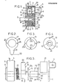
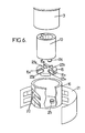
- a sensor 1 intended to identify the position or movement of a rotating shaft 2, firstly comprises a housing 3 of generally cylindrical shape, one of the faces of which is closed by a cover 4 which is welded, crimped or glued to the body 3a of the housing, this cover 4 carrying the connector 5 of the sensor, and the other lateral face 6 of which is an integral part of the body 3a of the housing, carries a circular tube 7 which is surrounded by a flange circular 8 concentric with the tube 7 and disposed outside and at a distance therefrom, this flange 7 serving for centering the housing 3 in a bore 9 which is crossed by the shaft 2.
- This rotating part 10 comprises a flat circular ring 11 and a tubular centering ring 12 which can rotate, with at least one play equal to the reasonably conceivable maximum concentricity error in the circular tube 7.
- the rotation of the rotating part 10 by the shaft 2 is ensured for example by providing a portion inside the centering ring 12 plane 13 which cooperates with a corresponding flat portion 14 formed on the free end 2a of the shaft 2.
- the rotating part 10 constitutes the first element of an Oldham seal which comprises two other rotating parts, namely an intermediate part 15 constituted by a flat circular crown and a second rotating part 16, which is a driven part, constitutes the rotor or rotating part of the sensor.
- the part 16 comprises a flat circular crown 17 which carries, on the one hand, a tubular portion 18, which can rotate with gentle friction around the circular tube 7, and, on the other hand, a brush-carrying element 19, the brushes 20 of which rub against a conductive track 21 disposed on a part 22 of the internal lateral surface of the housing 3.
- a helical return spring 26 is disposed, inside the housing 3, between the internal surface 27 of the side face 6 of the housing carrying the pipe 7 and the crown 17 of the second rotating part 16 to ensure the take-up of the play of rotation between the parts 2, 10, 15, 16 by exerting a return torque which ensures, when stopped or during the rotation of the shaft 2, the application of the planar portion 14 of the rotating shaft 2 on the internal flat portion 13 of the first rotating part 10, pins 24 on the notches 23a of the intermediate part 15, notches 23b on the pins 25 of the second rotating part 16.
- the rotation of the shaft 2 causes, by the flat surfaces 13 and 14, the rotation of the first rotating part 10 whose pins 24, by cooperating with the notches 23a of the intermediate part 15, drive the latter in rotation, while that the cooperation of the pins 25 of the second rotating part 16 and the notches 23b ensures the rotational drive of the second rotating part 16. Therefore the rotation of the shaft 2 causes the rotation of the second in a constant velocity manner rotating part 16 and therefore of the brush holder 19 whose brushes 20 move on the fixed conductive track 21 carried by the housing 3.
- the position of the brushes 20 on the conductive track 21 is processed in the connector 5 of the sensor and used as desired, in particular to ensure remote copying of the position or of the displacement of the rotating shaft 2.
Priority Applications (1)
| Application Number | Priority Date | Filing Date | Title |
|---|---|---|---|
| AT87400885T ATE47634T1 (de) | 1986-04-25 | 1987-04-17 | Derhpotentiometersensor fuer das bestimmen der position oder der drehbewegung einer drehenden welle. |
Applications Claiming Priority (2)
| Application Number | Priority Date | Filing Date | Title |
|---|---|---|---|
| FR8606049A FR2597970A1 (fr) | 1986-04-25 | 1986-04-25 | Capteur a potentiometre rotatif pour le reperage de la position ou du deplacement angulaire d'un arbre tournant |
| FR8606049 | 1986-04-25 |
Publications (2)
| Publication Number | Publication Date |
|---|---|
| EP0243254A1 true EP0243254A1 (de) | 1987-10-28 |
| EP0243254B1 EP0243254B1 (de) | 1989-10-25 |
Family
ID=9334646
Family Applications (1)
| Application Number | Title | Priority Date | Filing Date |
|---|---|---|---|
| EP87400885A Expired EP0243254B1 (de) | 1986-04-25 | 1987-04-17 | Derhpotentiometersensor für das Bestimmen der Position oder der Drehbewegung einer drehenden Welle |
Country Status (5)
| Country | Link |
|---|---|
| US (1) | US4743882A (de) |
| EP (1) | EP0243254B1 (de) |
| AT (1) | ATE47634T1 (de) |
| DE (1) | DE3760894D1 (de) |
| FR (1) | FR2597970A1 (de) |
Cited By (2)
| Publication number | Priority date | Publication date | Assignee | Title |
|---|---|---|---|---|
| US4870861A (en) * | 1986-10-24 | 1989-10-03 | Yazaki Corporation | Liquid level indicator |
| CN113701622A (zh) * | 2021-10-29 | 2021-11-26 | 成都宏明电子股份有限公司 | 一种用于测试角位移电位器回程差的同心定位装置 |
Families Citing this family (6)
| Publication number | Priority date | Publication date | Assignee | Title |
|---|---|---|---|---|
| US5200747A (en) * | 1990-12-13 | 1993-04-06 | Bourns, Inc. | Turn counting position sensor |
| US5460035A (en) * | 1993-06-23 | 1995-10-24 | Cts Corporation | Bearing free spring free throttle position sensor |
| US5539373A (en) * | 1993-11-08 | 1996-07-23 | Cts Corporation | Rotor structure for a position sensor |
| JP3724669B2 (ja) * | 1996-08-30 | 2005-12-07 | 船井電機株式会社 | 位置検出スイッチ |
| US6691678B1 (en) * | 2000-04-05 | 2004-02-17 | Hitachi, Ltd. | Throttle assembly for internal combustion engine, and throttle sensor |
| JP5692147B2 (ja) * | 2012-04-18 | 2015-04-01 | 株式会社安川電機 | 回転電機 |
Citations (2)
| Publication number | Priority date | Publication date | Assignee | Title |
|---|---|---|---|---|
| DE3042515A1 (de) * | 1980-11-11 | 1982-05-19 | Matsushita Electric Industrial Co., Ltd., Kadoma, Osaka | Elektronisches drehstellerelement |
| EP0185443A1 (de) * | 1984-11-13 | 1986-06-25 | General Motors Corporation | Auf der Drehachse eines Ventils montierter Positionsfühler |
Family Cites Families (5)
| Publication number | Priority date | Publication date | Assignee | Title |
|---|---|---|---|---|
| DE185443C (de) * | ||||
| US4355293A (en) * | 1979-10-22 | 1982-10-19 | The Bendix Corporation | Electrical resistance apparatus having integral shorting protection |
| US4430634A (en) * | 1982-01-18 | 1984-02-07 | Cts Corporation | Rotary potentiometer with molded terminal package |
| US4616504A (en) * | 1983-05-03 | 1986-10-14 | Duncan Electronics | Throttle position sensor |
| FR2560428B1 (fr) * | 1984-02-28 | 1987-02-27 | Renix Electronique Sa | Potentiometre rotatif notamment de mesure de position angulaire |
-
1986
- 1986-04-25 FR FR8606049A patent/FR2597970A1/fr active Pending
-
1987
- 1987-04-17 AT AT87400885T patent/ATE47634T1/de not_active IP Right Cessation
- 1987-04-17 EP EP87400885A patent/EP0243254B1/de not_active Expired
- 1987-04-17 DE DE8787400885T patent/DE3760894D1/de not_active Expired
- 1987-04-20 US US07/040,106 patent/US4743882A/en not_active Expired - Fee Related
Patent Citations (2)
| Publication number | Priority date | Publication date | Assignee | Title |
|---|---|---|---|---|
| DE3042515A1 (de) * | 1980-11-11 | 1982-05-19 | Matsushita Electric Industrial Co., Ltd., Kadoma, Osaka | Elektronisches drehstellerelement |
| EP0185443A1 (de) * | 1984-11-13 | 1986-06-25 | General Motors Corporation | Auf der Drehachse eines Ventils montierter Positionsfühler |
Cited By (3)
| Publication number | Priority date | Publication date | Assignee | Title |
|---|---|---|---|---|
| US4870861A (en) * | 1986-10-24 | 1989-10-03 | Yazaki Corporation | Liquid level indicator |
| CN113701622A (zh) * | 2021-10-29 | 2021-11-26 | 成都宏明电子股份有限公司 | 一种用于测试角位移电位器回程差的同心定位装置 |
| CN113701622B (zh) * | 2021-10-29 | 2022-03-18 | 成都宏明电子股份有限公司 | 一种用于测试角位移电位器回程差的同心定位装置 |
Also Published As
| Publication number | Publication date |
|---|---|
| FR2597970A1 (fr) | 1987-10-30 |
| DE3760894D1 (en) | 1989-11-30 |
| US4743882A (en) | 1988-05-10 |
| EP0243254B1 (de) | 1989-10-25 |
| ATE47634T1 (de) | 1989-11-15 |
Similar Documents
| Publication | Publication Date | Title |
|---|---|---|
| FR2664438A1 (fr) | Dispositif forme de deux elements articules autour d'une charniere et relies par une liaison electrique. | |
| FR2463339A1 (fr) | Joint d'etancheite mecanique pour arbre rotatif | |
| EP0243254B1 (de) | Derhpotentiometersensor für das Bestimmen der Position oder der Drehbewegung einer drehenden Welle | |
| FR2587426A1 (fr) | Roue libre munie d'un dispositif de mesure du couple transmis | |
| EP0616219A1 (de) | Baugruppe mit wasserdichter Abdichtung und Geschwindigkeitsmessaufnehmer | |
| EP0326454A1 (de) | Wälzlager mit Messwertgeber | |
| FR2568328A1 (fr) | Roulement a aiguilles, notamment douille a aiguilles a etancheite renforcee | |
| FR2471512A1 (fr) | Accouplement a friction pour transmettre un couple limite | |
| FR2463338A1 (fr) | Joint d'etancheite mecanique pour arbre rotatif | |
| WO1998050793A1 (fr) | Dispositif pour mesurer la rotation d'un element tournant | |
| EP0722542B1 (de) | Schwimmsattel- scheibenbremse und stift dafür | |
| FR2724430A1 (fr) | Dispositif de transmission a limitation de couple | |
| FR2641834A1 (fr) | Dispositif de commande d'un organe d'accouplement, en particulier pour vehicules automobiles | |
| EP0983924B1 (de) | Lenkradanordnung | |
| EP0482443A1 (de) | Bremsungsvorrichtung für ein Zahnrad | |
| EP0227511B1 (de) | Vorrichtung zum Zusammenklemmen von mindestens zwei Seite an Seite zu verbindenden Teilen und eine Klemmeinheit, die ein Klemmwerkzeug und obige Klemmvorrichtung enthält | |
| CA2412354A1 (fr) | Palier a roulement instrumente pour volant de commande | |
| EP1178910A1 (de) | Vorrichtung zum zurückbringen in die neutrale stellung , insbesondere eines lenkrades | |
| FR2839125A1 (fr) | Mecanisme d'embrayage a cones | |
| EP0649774B1 (de) | Einrichtung zum Festsetzen einer Schraube zur Steuerung der Neigung eines Scheinwerferreflektors | |
| FR2899329A1 (fr) | Agencement pour la mesure du couple et de la vitesse d'une roue de vehicule automobile | |
| EP0167415B1 (de) | Drehmomentbegrenzer | |
| FR2679303A1 (fr) | Dispositif de transmission a joint articule notamment pour vehicule automobile. | |
| EP0260196A1 (de) | Kupplungseinrichtung zwischen einer Motorenanlage und einer Wagenantriebswelle | |
| FR2662503A1 (fr) | Capteur electrique de vitesse pour vehicules automobiles. |
Legal Events
| Date | Code | Title | Description |
|---|---|---|---|
| PUAI | Public reference made under article 153(3) epc to a published international application that has entered the european phase |
Free format text: ORIGINAL CODE: 0009012 |
|
| AK | Designated contracting states |
Kind code of ref document: A1 Designated state(s): AT BE CH DE ES FR GB GR IT LI LU NL SE |
|
| 17P | Request for examination filed |
Effective date: 19870918 |
|
| 17Q | First examination report despatched |
Effective date: 19890216 |
|
| GRAA | (expected) grant |
Free format text: ORIGINAL CODE: 0009210 |
|
| ITF | It: translation for a ep patent filed |
Owner name: UFFICIO TECNICO ING. A. MANNUCCI |
|
| AK | Designated contracting states |
Kind code of ref document: B1 Designated state(s): AT BE CH DE ES FR GB GR IT LI LU NL SE |
|
| PG25 | Lapsed in a contracting state [announced via postgrant information from national office to epo] |
Ref country code: SE Effective date: 19891025 Ref country code: NL Effective date: 19891025 Ref country code: GR Free format text: LAPSE BECAUSE OF FAILURE TO SUBMIT A TRANSLATION OF THE DESCRIPTION OR TO PAY THE FEE WITHIN THE PRESCRIBED TIME-LIMIT Effective date: 19891025 Ref country code: AT Effective date: 19891025 |
|
| REF | Corresponds to: |
Ref document number: 47634 Country of ref document: AT Date of ref document: 19891115 Kind code of ref document: T |
|
| GBT | Gb: translation of ep patent filed (gb section 77(6)(a)/1977) | ||
| REF | Corresponds to: |
Ref document number: 3760894 Country of ref document: DE Date of ref document: 19891130 |
|
| PG25 | Lapsed in a contracting state [announced via postgrant information from national office to epo] |
Ref country code: ES Free format text: LAPSE BECAUSE OF FAILURE TO SUBMIT A TRANSLATION OF THE DESCRIPTION OR TO PAY THE FEE WITHIN THE PRESCRIBED TIME-LIMIT Effective date: 19900205 |
|
| NLV1 | Nl: lapsed or annulled due to failure to fulfill the requirements of art. 29p and 29m of the patents act | ||
| PG25 | Lapsed in a contracting state [announced via postgrant information from national office to epo] |
Ref country code: LU Free format text: LAPSE BECAUSE OF NON-PAYMENT OF DUE FEES Effective date: 19900430 Ref country code: LI Effective date: 19900430 Ref country code: CH Effective date: 19900430 Ref country code: BE Effective date: 19900430 |
|
| PLBE | No opposition filed within time limit |
Free format text: ORIGINAL CODE: 0009261 |
|
| STAA | Information on the status of an ep patent application or granted ep patent |
Free format text: STATUS: NO OPPOSITION FILED WITHIN TIME LIMIT |
|
| 26N | No opposition filed | ||
| BERE | Be: lapsed |
Owner name: M.C.B. Effective date: 19900430 |
|
| REG | Reference to a national code |
Ref country code: CH Ref legal event code: PL |
|
| PGFP | Annual fee paid to national office [announced via postgrant information from national office to epo] |
Ref country code: FR Payment date: 19920221 Year of fee payment: 6 |
|
| PGFP | Annual fee paid to national office [announced via postgrant information from national office to epo] |
Ref country code: DE Payment date: 19920229 Year of fee payment: 6 |
|
| PGFP | Annual fee paid to national office [announced via postgrant information from national office to epo] |
Ref country code: GB Payment date: 19920410 Year of fee payment: 6 |
|
| ITTA | It: last paid annual fee | ||
| PG25 | Lapsed in a contracting state [announced via postgrant information from national office to epo] |
Ref country code: GB Effective date: 19930417 |
|
| GBPC | Gb: european patent ceased through non-payment of renewal fee |
Effective date: 19930417 |
|
| PG25 | Lapsed in a contracting state [announced via postgrant information from national office to epo] |
Ref country code: FR Effective date: 19931229 |
|
| PG25 | Lapsed in a contracting state [announced via postgrant information from national office to epo] |
Ref country code: DE Effective date: 19940101 |
|
| REG | Reference to a national code |
Ref country code: FR Ref legal event code: ST |
|
| PG25 | Lapsed in a contracting state [announced via postgrant information from national office to epo] |
Ref country code: IT Free format text: LAPSE BECAUSE OF NON-PAYMENT OF DUE FEES;WARNING: LAPSES OF ITALIAN PATENTS WITH EFFECTIVE DATE BEFORE 2007 MAY HAVE OCCURRED AT ANY TIME BEFORE 2007. THE CORRECT EFFECTIVE DATE MAY BE DIFFERENT FROM THE ONE RECORDED. Effective date: 20050417 |