EP0243254A1 - Rotary potentiometer sensor for determining the position or the angular displacement of a rotating shaft - Google Patents
Rotary potentiometer sensor for determining the position or the angular displacement of a rotating shaft Download PDFInfo
- Publication number
- EP0243254A1 EP0243254A1 EP87400885A EP87400885A EP0243254A1 EP 0243254 A1 EP0243254 A1 EP 0243254A1 EP 87400885 A EP87400885 A EP 87400885A EP 87400885 A EP87400885 A EP 87400885A EP 0243254 A1 EP0243254 A1 EP 0243254A1
- Authority
- EP
- European Patent Office
- Prior art keywords
- rotating
- shaft
- sensor
- housing
- rotating part
- Prior art date
- Legal status (The legal status is an assumption and is not a legal conclusion. Google has not performed a legal analysis and makes no representation as to the accuracy of the status listed.)
- Granted
Links
Images
Classifications
-
- H—ELECTRICITY
- H01—ELECTRIC ELEMENTS
- H01C—RESISTORS
- H01C10/00—Adjustable resistors
- H01C10/14—Adjustable resistors adjustable by auxiliary driving means
-
- H—ELECTRICITY
- H01—ELECTRIC ELEMENTS
- H01C—RESISTORS
- H01C10/00—Adjustable resistors
- H01C10/30—Adjustable resistors the contact sliding along resistive element
- H01C10/32—Adjustable resistors the contact sliding along resistive element the contact moving in an arcuate path
Definitions
- the present invention relates to rotary potentiometer sensors for locating the position or angular displacement of a rotating shaft.
- such sensors in order to determine the position or the displacement of a rotating shaft, in particular in order to copy this position or this displacement from a distance.
- the accuracy of the indications provided by a potentiometric sensor on the position or the angular displacement of a rotating shaft is generally limited by the error of concentricity between this shaft and the sensor. Indeed, between the rotating part or rotor of the sensor and the shaft whose position or displacement we want to know, we must provide a constant velocity joint, which has the disadvantage of requiring space, complicating the mounting between the 'shaft and the sensor and to expose to dust and various projections this seal, especially in the case where the potentiometric sensor is placed under the hood of an automobile, hence premature wear; thought has been given to protecting the joint, but this requires additional parts which increase the cost and the bulk.
- the invention aims to overcome the aforementioned drawbacks by arranging the seal between the shaft, the position or displacement of which is to be known, and the rotating part of the sensor, around the free end of said shaft, which reduces the bulk. , by accommodating said end of the shaft and the rotating joint itself inside the sensor housing, which ensures the pro tection of the joint at no additional cost.
- the sensor according to the invention makes it possible, in particular in its application to automobiles, to obtain a very high angular precision, for example less than 1 ′, without precision machining and without requiring costly additional parts.
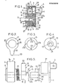
- a sensor 1 intended to identify the position or movement of a rotating shaft 2, firstly comprises a housing 3 of generally cylindrical shape, one of the faces of which is closed by a cover 4 which is welded, crimped or glued to the body 3a of the housing, this cover 4 carrying the connector 5 of the sensor, and the other lateral face 6 of which is an integral part of the body 3a of the housing, carries a circular tube 7 which is surrounded by a flange circular 8 concentric with the tube 7 and disposed outside and at a distance therefrom, this flange 7 serving for centering the housing 3 in a bore 9 which is crossed by the shaft 2.
- This rotating part 10 comprises a flat circular ring 11 and a tubular centering ring 12 which can rotate, with at least one play equal to the reasonably conceivable maximum concentricity error in the circular tube 7.
- the rotation of the rotating part 10 by the shaft 2 is ensured for example by providing a portion inside the centering ring 12 plane 13 which cooperates with a corresponding flat portion 14 formed on the free end 2a of the shaft 2.
- the rotating part 10 constitutes the first element of an Oldham seal which comprises two other rotating parts, namely an intermediate part 15 constituted by a flat circular crown and a second rotating part 16, which is a driven part, constitutes the rotor or rotating part of the sensor.
- the part 16 comprises a flat circular crown 17 which carries, on the one hand, a tubular portion 18, which can rotate with gentle friction around the circular tube 7, and, on the other hand, a brush-carrying element 19, the brushes 20 of which rub against a conductive track 21 disposed on a part 22 of the internal lateral surface of the housing 3.
- a helical return spring 26 is disposed, inside the housing 3, between the internal surface 27 of the side face 6 of the housing carrying the pipe 7 and the crown 17 of the second rotating part 16 to ensure the take-up of the play of rotation between the parts 2, 10, 15, 16 by exerting a return torque which ensures, when stopped or during the rotation of the shaft 2, the application of the planar portion 14 of the rotating shaft 2 on the internal flat portion 13 of the first rotating part 10, pins 24 on the notches 23a of the intermediate part 15, notches 23b on the pins 25 of the second rotating part 16.
- the rotation of the shaft 2 causes, by the flat surfaces 13 and 14, the rotation of the first rotating part 10 whose pins 24, by cooperating with the notches 23a of the intermediate part 15, drive the latter in rotation, while that the cooperation of the pins 25 of the second rotating part 16 and the notches 23b ensures the rotational drive of the second rotating part 16. Therefore the rotation of the shaft 2 causes the rotation of the second in a constant velocity manner rotating part 16 and therefore of the brush holder 19 whose brushes 20 move on the fixed conductive track 21 carried by the housing 3.
- the position of the brushes 20 on the conductive track 21 is processed in the connector 5 of the sensor and used as desired, in particular to ensure remote copying of the position or of the displacement of the rotating shaft 2.
Abstract
Description
La présente invention est relative aux capteurs à potentiomètre rotatif destinés à repérer la position ou le déplacement angulaire d'un arbre tournant.The present invention relates to rotary potentiometer sensors for locating the position or angular displacement of a rotating shaft.
On utilise fréquemment dans les dispositifs et appareils industriels, en particulier dans les automobiles, de tels capteurs afin de déterminer la position ou le déplacement d'un arbre tournant, notamment afin de recopier cette position ou ce déplacement à distance.Frequently used in industrial devices and apparatuses, in particular in automobiles, such sensors in order to determine the position or the displacement of a rotating shaft, in particular in order to copy this position or this displacement from a distance.
La précision des indications fournies par un capteur potentiométrique sur la position ou le déplacement angulaire d'un arbre tournant est généralement limitée par l'erreur de concentricité entre cet arbre et le capteur. En effet, entre la partie tournante ou rotor du capteur et l'arbre dont on veut connaître la position ou le déplacement, on doit prévoir un joint homocinétique, ce qui a pour inconvénient d'exiger de la place, de compliquer le montage entre l'arbre et le capteur et d'exposer aux poussières et aux projections diverses ce joint, notamment dans le cas où le capteur potentiométrique est disposé sous le capot d'une d'automobile, d'où une usure prématurée; on a bien pensé à protéger le joint, mais ceci exige des pièces supplémentaires qui augmentent le coût et l'encombrement.The accuracy of the indications provided by a potentiometric sensor on the position or the angular displacement of a rotating shaft is generally limited by the error of concentricity between this shaft and the sensor. Indeed, between the rotating part or rotor of the sensor and the shaft whose position or displacement we want to know, we must provide a constant velocity joint, which has the disadvantage of requiring space, complicating the mounting between the 'shaft and the sensor and to expose to dust and various projections this seal, especially in the case where the potentiometric sensor is placed under the hood of an automobile, hence premature wear; thought has been given to protecting the joint, but this requires additional parts which increase the cost and the bulk.
L'invention vise à pallier les inconvénients précités en disposant le joint entre l'arbre, dont on veut connaître la position ou le déplacement, et la partie tournante du capteur, autour de l'extrémité libre dudit arbre, ce qui réduit l'encombrement, en logeant ladite extrémité de l'arbre et le joint tournant lui-même à l'intérieur du boîtier du capteur, ce qui assure la protection du joint sans coût supplémentaire.The invention aims to overcome the aforementioned drawbacks by arranging the seal between the shaft, the position or displacement of which is to be known, and the rotating part of the sensor, around the free end of said shaft, which reduces the bulk. , by accommodating said end of the shaft and the rotating joint itself inside the sensor housing, which ensures the pro tection of the joint at no additional cost.
Le capteur selon l'invention permet, notamment dans son application aux automobiles, d'obtenir une précision angulaire très grande, par exemple inférieure à 1', sans usinage de précision et sans nécessiter des pièces supplémentaires coûteuses.The sensor according to the invention makes it possible, in particular in its application to automobiles, to obtain a very high angular precision, for example less than 1 ′, without precision machining and without requiring costly additional parts.
Plus précisément l'invention a pour objet un capteur à potentiomètre rotatif pour le repérage de la position ou du déplacement angulaire d'un arbre tournant, qui comporte, pour la transmission homocinétique de la rotation dudit arbre à la partie tournante ou rotor du capteur, un joint du type Oldham avec, d'une part, trois pièces tournantes, à savoir une première pièce portée et entraînée en rotation par ledit arbre, une deuxième pièce apte à tourner à l'intérieur du capteur dont elle constitue la partie tournante ou rotor et une troisième pièce, dite pièce intermédiaire, disposée entre la première et la deuxième pièces, et, d'autre part, des moyens, prévus sur ces trois pièces, pour assurer l'entrainement en rotation homocinétique de la pièce intermédiaire par la première pièce et de la deuxième pièce par la pièce intermédiaire, tout en permettant un débattement angulaire entre l'axe dudit arbre et l'axe de la partie tournante ou rotor du capteur, capteur caractérisé en ce qu'il comporte un boltier de forme générale cylindrique contenant l'extrémité libre dudit arbre tournant et les trois pièces tournantes dudit joint, ce boitier présentant deux faces latérales dont l'une est complètement fermée par un couvercle solidaire du boitier et dont l'autre est traversée par un tube circulaire solidaire du boitier et dont l'alésage interne reçoit, avec un jeu au moins égal à l'erreur de concentricité maximale raisonnablement envisageable, ladite première pièce tournante qui coiffe ladite extrémité libre dudit arbre et dont la surface périphérique est entourée, avec le jeu précité, par ladite deuxième pièce tournante et ladite pièce intermédiaire tournante. Avantageusement :
- - la première pièce tournante comporte une portion tubulaire qui entoure l'extrémité libre de l'arbre tournant et qui peut tourner à frottement doux à l'intérieur dudit tube circulaire;
- - la deuxième pièce tournante comporte une portion tubulaire, qui peut tourner à frottement doux autour dudit tube circulaire, et un élément porte-balais, dont les balais frottent sur une piste conductrice disposée sur une partie de la surface latérale interne du boîtier;
- - le couvercle du boîtier porte le connecteur du capteur;
- - le boîtier comporte, du côté de la face latérale qui porte ledit tube circulaire, une collerette circulaire concentrique audit tube et disposée à l'extérieur et à distance de celui-ci, cette collerette servant au centrage du boîtier dans un alésage traversé par ledit arbre;
- - la pièce intermédiaire est une couronne circulaire plate, tandis que lesdites première et deuxième pièces tournantes comportent des couronnes circulaires plates, et les moyens d'entrainement en rotation homocinétique des trois pièces tournantes, avec possibilité de débattement angulaire, sont constituées par quatre encoches radiales prévues sur la périphérie de la pièce intermédiaire, à 90* chacune de la précédente dans le sens périphérique, et par deux paires de tétons portées par les couronnes circulaires plates de respectivement ladite première et ladite deuxième pièce tournante sur leur face dirigée vers la pièce intermédiaire, les deux tétons d'une même paire étant diamétralement opposés et la droite réunissant les centres des deux tétons de la paire de la première pièce tournante étant orthogonale à la droite réunissant les centres des deux tétons de la paire de la deuxième pièce tournante;
- - la première pièce tournante porte une protubérance centrale contre sa face qui est dirigée du côté du couvercle du boîtier;
- - l'extrémité libre de l'arbre tournant comporte une portion plane qui coopère avec une portion plane que comporte à son intérieur la portion tubulaire de la première pièce tournante.
- - The first rotating part comprises a tubular portion which surrounds the free end of the rotating shaft and which can rotate with gentle friction inside said circular tube;
- - The second rotating part comprises a tubular portion, which can rotate with gentle friction around said circular tube, and a brush-carrying element, the brushes of which rub on a conductive track disposed on a part of the internal lateral surface of the housing;
- - the housing cover carries the sensor connector;
- - The housing comprises, on the side of the side face which carries said circular tube, a circular flange concentric with said tube and disposed outside and at a distance therefrom, this flange serving for centering the housing in a bore through which said tree;
- - The intermediate part is a flat circular crown, while said first and second rotating parts comprise flat circular crowns, and the means for driving the constant velocity rotation of the three rotating parts, with the possibility of angular movement, are constituted by four radial notches provided on the periphery of the intermediate piece, 90 * each of the previous one in the peripheral direction, and by two pairs of studs carried by the flat circular crowns of said first and said second rotating part respectively on their face directed towards the intermediate piece , the two nipples of the same pair being diametrically opposite and the straight line joining the centers of the two nipples of the pair of the first rotating part being orthogonal to the right joining the centers of the two nipples of the pair of the second rotating part;
- - the first rotating part carries a central protuberance against its face which is directed towards the side of the housing cover;
- - The free end of the rotating shaft has a planar portion which cooperates with a planar portion which has inside it the tubular portion of the first rotating part.
Afin d'assurer la coopération efficace entre les trois pièces tournantes, on peut prévoir :
- - dans un premier mode de réalisation, un ressort hélicoïdal de rappel disposé, à l'intérieur du boîtier, entre la surface interne de la face latérale du boîtier portant ledit tube circulaire et la deuxième pièce tournante pour appliquer cette deuxième pièce contre la pièce intermédiaire, cette pièce intermédiaire contre la première pièce tournante et cette première pièce contre le couvercle du boîtier;
- - dans un second mode de réalisation des languettes faisant partie intégrante de la pièce intermédiaire et maintenant lesdites paires de tétons en contact chacune avec la face en regard de la pièce intermédiaire;
- - In a first embodiment, a helical return spring disposed, inside the housing, between the internal surface of the side face of the housing carrying said circular tube and the second rotating part to apply this second part against the intermediate part , this intermediate part against the first rotating part and this first part against the housing cover;
- - In a second embodiment of the tongues forming an integral part of the intermediate piece and maintaining said pairs of pins each in contact with the opposite face of the intermediate piece;
L'invention pourra, de toute façon, être bien comprise à l'aide du complément de description qui suit, ainsi que des dessins ci-annexés, lesquels complément et dessins sont, bien entendu, donnés surtout à titre d'indication.
- La figure 1 est une coupe d'un capteur à potentiomètre rotatif, montrant les dispositions selon l'invention.
- Les figures 2, 3 et 4 représentent les trois pièces tournantes du joint de type Oldham que comporte ce capteur, à savoir respectivement ladite deuxième pièce, ladite pièce intermédiaire et ladite première pièce.
- La figure 5 est une vue éclatée du capteur de la figure 1.
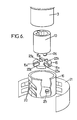
- La figure 6, enfin, illustre en vue éclatée partielle une variante du capteur.
- Figure 1 is a section of a rotary potentiometer sensor, showing the arrangements according to the invention.
- Figures 2, 3 and 4 show the three rotating parts of the Oldham type seal that includes this sensor, namely respectively said second part, said intermediate part and said first part.
- FIG. 5 is an exploded view of the sensor of FIG. 1.
- Figure 6, finally, illustrates in partial exploded view a variant of the sensor.
Selon l'invention, et plus spécialement selon celui de ses modes d'application, auquel il semble qu'il y ait lieu d'accorder la préférence, se proposant, de réaliser un capteur à potentiomètre rotatif pour le repérage de la position ou du déplacement d'un arbre tournant, on s'y prend comme suit ou d'une manière analogue.According to the invention, and more especially according to that of its modes of application, to which it seems that there is reason to give preference, proposing, to produce a sensor with a rotary potentiometer for locating the position or the displacement of a rotating shaft, we s takes it as follows or in a similar manner.
Un capteur 1 selon l'invention, destiné à repérer la position ou le déplacement d'un arbre tournant 2, comporte tout d'abord un boîtier 3 de forme générale cylindrique, dont une des faces est fermée par un couvercle 4 qui est soudé, serti ou collé sur le corps 3a du boitier, ce couvercle 4 portant le connecteur 5 du capteur, et dont l'autre face latérale 6, qui fait partie intégrante du corps 3a du boîtier, porte un tube circulaire 7 qui est entouré par une collerette circulaire 8 concentrique au tube 7 et disposée à l'extérieur et à distance de celui-ci, cette collerette 7 servant au centrage du boîtier 3 dans un alésage 9 qui est traversé par l'arbre 2.A sensor 1 according to the invention, intended to identify the position or movement of a rotating shaft 2, firstly comprises a
Une première pièce tournante 10, qui est une pièce d'entraînement, est solidaire en rotation de l'arbre 2. Cette pièce tournante 10 comporte une couronne circulaire plate 11 et une bague de centrage tubulaire 12 qui peut tourner, avec un jeu au moins égal à l'erreur de concentricité maximale raisonnablement envisageable, dans le tube circulaire 7. L'entraînement en rotation de la pièce tournante 10 par l'arbre 2 est assuré par exemple en prévoyant à l'intérieur de la bague de centrage 12 une portion plane 13 qui coopère avec une portion plane correspondante 14 ménagée sur l'extrémité libre 2a de l'arbre 2.A first rotating
La pièce tournante 10 constitue le premier élément d'un joint de Oldham qui comporte deux autres pièces tournantes, à savoir une pièce intermédiaire 15 constituée par une couronne circulaire plate et une deuxième pièce tournante 16, qui est une pièce entraînée, constitue le rotor ou partie tournante du capteur.The rotating
La pièce 16 comprend une couronne circulaire plate 17 qui porte, d'une part, une portion tubulaire 18, qui peut tourner à frottement doux autour du tube circulaire 7, et, d'autre part, un élément porte-balais 19 dont les balais 20 frottent sur une piste conductrice 21 disposée sur une partie 22 de la surface latérale interne du boitier 3.The
La solidarisation en rotation entre les trois éléments 10, 15 et 16 du joint d'Oldham, tout en permettant un débattement angulaire entre l'axe de l'arbre 2 et l'axe de la partie tournante ou rotor du capteur, est assurée de la manière suivante :
- - la pièce intermédiaire 15 présente deux
encoches 23a et deuxencoches 23b disposées à 90' chacune de la précédente, dans le sens périphérique, les deuxencoches 23a, d'une part, et 23b, d'autre part, étant diamétralement opposées; - - la première pièce tournante 10 comporte deux
tétons 24, diamétralement opposés, portés par la face de la couronne circulaire 11 de cettepièce 10 qui est dirigée du côté de la pièce intermédiaire 15, cestétons 24 pénétrant dans lesencoches 23a de la pièce intermédiaire 15; et - - la deuxième pièce tournante 16 comporte deux
tétons 25, diamétralement opposés, portés par la face de la couronne circulaire plate 17 de cettepièce 16 qui est dirigée du côté de la pièce intermédiaire 15, cestétons 25 pénétrant dans lesencoches 23b de cettepièce 15.
- - The
intermediate piece 15 has twonotches 23a and twonotches 23b arranged 90 'each from the previous one, in the peripheral direction, the twonotches 23a, on the one hand, and 23b, on the other hand, being diametrically opposite; - - The first rotating
part 10 comprises twostuds 24, diametrically opposite, carried by the face of thecircular crown 11 of thispiece 10 which is directed towards the side of theintermediate piece 15, thesestuds 24 penetrating into thenotches 23a of theintermediate piece 15; and - - The second rotating
part 16 comprises twopins 25, diametrically opposite, carried by the face of the flatcircular crown 17 of thispart 16 which is directed towards the side of theintermediate part 15, thesepins 25 penetrating into thenotches 23b of thispart 15.
Un ressort hélicoidal de rappel 26 est disposé, à l'intérieur du boîtier 3,entre la surface interne 27 de la face latérale 6 du boitier portant le tuyau 7 et la couronne 17 de la deuxième pièce tournante 16 pour assurer le rattrapage du jeu de rotation entre les pièces 2, 10, 15, 16 en exerçant un couple de rappel qui assure, à l'arrêt ou pendant la rotation de l'arbre 2, l'application de la portion plane 14 de l'arbre tournant 2 sur la portion plane interne 13 de la première pièce tournante 10, des tétons 24 sur les encoches 23a de la pièce intermédiaire 15, des encoches 23b sur les tétons 25 de la deuxième pièce tournante 16.A
Une protubérance centrale 28,portée par la face 29 de la couronne circulaire 11 qui est en regard du couvercle 4,assure le contact,avec possibilité de débattement, entre la couronne circulaire 11 de la première pièce tournante 10 et le couvercle 4 en réduisant le frottement.A
Le fonctionnement du capteur potentiométrique se- ion l'invention est le suivant.The operation of the potentiometric sensor according to the invention is as follows.
La rotation de l'arbre 2 entraine, par les surfaces planes 13 et 14, la rotation de la première pièce tournante 10 dont les tétons 24, en coopérant avec les encoches 23a de la pièce intermédiaire 15, entraînent celle-ci en rotation, tandis que la coopération des tétons 25 de la deuxième pièce tournante 16 et des encoches 23b assure l'entraînement en rotation de la deuxième pièce tournante 16. De ce fait la rotation de l'arbre 2 entraine d'une manière homocinétique la rotation de la deuxième pièce tournante 16 et donc du porte-balais 19 dont les balais 20 se déplacent sur la piste conductrice fixe 21 portée par le boîtier 3.The rotation of the shaft 2 causes, by the
A la manière connue, la position des balais 20 sur la piste conductrice 21 est traitée dans le connecteur 5 du capteur et utilisée comme désiré, notamment pour assurer la recopie à distance de la position ou du déplacement de l'arbre tournant 2.'In the known manner, the position of the
Dans une variante illustrée sur la figure 6 (sur laquelle on retrouve le boîtier 3 et les trois pièces tournantes 10, 15 et 16, ainsi que les tétons 24 de la pièce 10 et 25 de la pièce 16, et les encoches 23a, 23b de la pièce 15), on a remplacé le ressort 26 du mode de réalisation des figures 1 à 5 par quatre languettes 15a faisant partie intégrante de la pièce intermédiaire 15 et qui maintiennent les tétons 24 et 25 en contact avec la face en regard de cette pièce 15.In a variant illustrated in Figure 6 (in which we find the
On réalise ainsi, selon l'invention - et notamment selon les deux modes de réalisation (figures 1-5 et figure 6) particulièrement décrits - un capteur compact, bien à l'abri des poussières et qui permet d'obtenir une précision très grande du repérage de la position ou du déplacement d'un arbre tournant, par exemple une précision inférieure à 1.Thus, according to the invention - and in particular according to the two embodiments (FIGS. 1-5 and FIG. 6 ) which are particularly described - a compact sensor, well protected from dust and which makes it possible to obtain very high accuracy in locating the position or moving a rotating shaft, for example an accuracy of less than 1.
Comme il va de soi et comme il résulte d'ailleurs déjà de ce qui précède, l'invention ne se limite nullement à ceux de ses modes d'application et de réalisation qui ont été plus spécialement envisagés; elle en embrasse, au contraire, toutes les variantes.As goes without saying and as it already follows from the foregoing, the invention is in no way limited to those of its modes of application and embodiments which have been more especially envisaged; on the contrary, it embraces all its variants.
Claims (10)
Priority Applications (1)
| Application Number | Priority Date | Filing Date | Title |
|---|---|---|---|
| AT87400885T ATE47634T1 (en) | 1986-04-25 | 1987-04-17 | THEHPOTENTIOMETER SENSOR FOR DETERMINING THE POSITION OR ROTATIONAL MOVEMENT OF A ROTATING SHAFT. |
Applications Claiming Priority (2)
| Application Number | Priority Date | Filing Date | Title |
|---|---|---|---|
| FR8606049 | 1986-04-25 | ||
| FR8606049A FR2597970A1 (en) | 1986-04-25 | 1986-04-25 | SENSOR WITH ROTARY POTENTIOMETER FOR LOCATING THE ANGULAR POSITION OR MOVEMENT OF A ROTATING SHAFT |
Publications (2)
| Publication Number | Publication Date |
|---|---|
| EP0243254A1 true EP0243254A1 (en) | 1987-10-28 |
| EP0243254B1 EP0243254B1 (en) | 1989-10-25 |
Family
ID=9334646
Family Applications (1)
| Application Number | Title | Priority Date | Filing Date |
|---|---|---|---|
| EP87400885A Expired EP0243254B1 (en) | 1986-04-25 | 1987-04-17 | Rotary potentiometer sensor for determining the position or the angular displacement of a rotating shaft |
Country Status (5)
| Country | Link |
|---|---|
| US (1) | US4743882A (en) |
| EP (1) | EP0243254B1 (en) |
| AT (1) | ATE47634T1 (en) |
| DE (1) | DE3760894D1 (en) |
| FR (1) | FR2597970A1 (en) |
Cited By (2)
| Publication number | Priority date | Publication date | Assignee | Title |
|---|---|---|---|---|
| US4870861A (en) * | 1986-10-24 | 1989-10-03 | Yazaki Corporation | Liquid level indicator |
| CN113701622A (en) * | 2021-10-29 | 2021-11-26 | 成都宏明电子股份有限公司 | Concentric positioning device for testing return stroke difference of angular displacement potentiometer |
Families Citing this family (6)
| Publication number | Priority date | Publication date | Assignee | Title |
|---|---|---|---|---|
| US5200747A (en) * | 1990-12-13 | 1993-04-06 | Bourns, Inc. | Turn counting position sensor |
| US5460035A (en) * | 1993-06-23 | 1995-10-24 | Cts Corporation | Bearing free spring free throttle position sensor |
| US5539373A (en) * | 1993-11-08 | 1996-07-23 | Cts Corporation | Rotor structure for a position sensor |
| JP3724669B2 (en) * | 1996-08-30 | 2005-12-07 | 船井電機株式会社 | Position detection switch |
| US6691678B1 (en) * | 2000-04-05 | 2004-02-17 | Hitachi, Ltd. | Throttle assembly for internal combustion engine, and throttle sensor |
| JP5692147B2 (en) * | 2012-04-18 | 2015-04-01 | 株式会社安川電機 | Rotating electric machine |
Citations (2)
| Publication number | Priority date | Publication date | Assignee | Title |
|---|---|---|---|---|
| DE3042515A1 (en) * | 1980-11-11 | 1982-05-19 | Matsushita Electric Industrial Co., Ltd., Kadoma, Osaka | Rotary adjustable electronic component - has step reduced diameter spindle for adjustment control and to accommodate miniature component |
| EP0185443A1 (en) * | 1984-11-13 | 1986-06-25 | General Motors Corporation | Shaft-mounted valve position sensor |
Family Cites Families (5)
| Publication number | Priority date | Publication date | Assignee | Title |
|---|---|---|---|---|
| DE185443C (en) * | ||||
| US4355293A (en) * | 1979-10-22 | 1982-10-19 | The Bendix Corporation | Electrical resistance apparatus having integral shorting protection |
| US4430634A (en) * | 1982-01-18 | 1984-02-07 | Cts Corporation | Rotary potentiometer with molded terminal package |
| US4616504A (en) * | 1983-05-03 | 1986-10-14 | Duncan Electronics | Throttle position sensor |
| FR2560428B1 (en) * | 1984-02-28 | 1987-02-27 | Renix Electronique Sa | ROTARY POTENTIOMETER IN PARTICULAR FOR ANGULAR POSITION MEASUREMENT |
-
1986
- 1986-04-25 FR FR8606049A patent/FR2597970A1/en active Pending
-
1987
- 1987-04-17 AT AT87400885T patent/ATE47634T1/en not_active IP Right Cessation
- 1987-04-17 EP EP87400885A patent/EP0243254B1/en not_active Expired
- 1987-04-17 DE DE8787400885T patent/DE3760894D1/en not_active Expired
- 1987-04-20 US US07/040,106 patent/US4743882A/en not_active Expired - Fee Related
Patent Citations (2)
| Publication number | Priority date | Publication date | Assignee | Title |
|---|---|---|---|---|
| DE3042515A1 (en) * | 1980-11-11 | 1982-05-19 | Matsushita Electric Industrial Co., Ltd., Kadoma, Osaka | Rotary adjustable electronic component - has step reduced diameter spindle for adjustment control and to accommodate miniature component |
| EP0185443A1 (en) * | 1984-11-13 | 1986-06-25 | General Motors Corporation | Shaft-mounted valve position sensor |
Cited By (3)
| Publication number | Priority date | Publication date | Assignee | Title |
|---|---|---|---|---|
| US4870861A (en) * | 1986-10-24 | 1989-10-03 | Yazaki Corporation | Liquid level indicator |
| CN113701622A (en) * | 2021-10-29 | 2021-11-26 | 成都宏明电子股份有限公司 | Concentric positioning device for testing return stroke difference of angular displacement potentiometer |
| CN113701622B (en) * | 2021-10-29 | 2022-03-18 | 成都宏明电子股份有限公司 | Concentric positioning device for testing return stroke difference of angular displacement potentiometer |
Also Published As
| Publication number | Publication date |
|---|---|
| ATE47634T1 (en) | 1989-11-15 |
| US4743882A (en) | 1988-05-10 |
| DE3760894D1 (en) | 1989-11-30 |
| EP0243254B1 (en) | 1989-10-25 |
| FR2597970A1 (en) | 1987-10-30 |
Similar Documents
| Publication | Publication Date | Title |
|---|---|---|
| FR2664438A1 (en) | DEVICE MADE OF TWO ARTICULATED ELEMENTS AROUND A HINGE AND CONNECTED THROUGH AN ELECTRICAL CONNECTION. | |
| FR2463339A1 (en) | MECHANICAL SEAL FOR ROTARY SHAFT | |
| EP0243254B1 (en) | Rotary potentiometer sensor for determining the position or the angular displacement of a rotating shaft | |
| FR2587426A1 (en) | FREE WHEEL HAVING A TORQUE MEASURING DEVICE TRANSMITTED | |
| EP0616219A1 (en) | Assembly with a waterproof seal and a speed sensor | |
| EP0326454A1 (en) | Ball bearing with a sensor device | |
| FR2568328A1 (en) | NEEDLE BEARING, IN PARTICULAR NEEDLE SOCKET WITH REINFORCED SEAL | |
| FR2471512A1 (en) | FRICTION COUPLING FOR TRANSMITTING A LIMIT TORQUE | |
| FR2463338A1 (en) | MECHANICAL SEAL FOR ROTARY SHAFT | |
| WO1998050793A1 (en) | Device for measuring the rotation of a rotating element | |
| EP0722542B1 (en) | Disk brake with sliding caliper and stud for such disk brake | |
| FR2724430A1 (en) | TORQUE LIMITATION TRANSMISSION DEVICE | |
| FR2641834A1 (en) | DEVICE FOR CONTROLLING A COUPLING DEVICE, ESPECIALLY FOR MOTOR VEHICLES | |
| EP0983924B1 (en) | Steering wheel device | |
| EP0482443A1 (en) | Braking device for a gear-wheel | |
| EP0227511B1 (en) | Device to clamp at least two parts side by side to be jointed, and a clamping unit comprising a clamping tool and said clamping device | |
| CA2412354A1 (en) | Instrumented antifriction bearing for control wheel | |
| EP1178910A1 (en) | Neutral point setting device for steering wheel in particular | |
| FR2839125A1 (en) | Friction cone clutch mechanism has toothed wheel of synthetic material with inner bore shaped to receive metal rings interacting with cones | |
| EP0649774B1 (en) | Device for fixing a screw for controlling the orientation of a headlight reflector | |
| FR2899329A1 (en) | Drive wheel`s torque and speed measuring arrangement for motor vehicle, has drive shaft to drive drive wheel, and measurement device to measure torque and speed of shaft, where shaft has cylindrical section for integrally carrying device | |
| EP0167415B1 (en) | Torque limiter | |
| FR2679303A1 (en) | Transmission device with articulated joint particularly for a motor vehicle | |
| EP0260196A1 (en) | Device for connecting a driving motor assembly to a vehicle drive shaft | |
| FR2662503A1 (en) | Electronic speed sensor for motor vehicles |
Legal Events
| Date | Code | Title | Description |
|---|---|---|---|
| PUAI | Public reference made under article 153(3) epc to a published international application that has entered the european phase |
Free format text: ORIGINAL CODE: 0009012 |
|
| AK | Designated contracting states |
Kind code of ref document: A1 Designated state(s): AT BE CH DE ES FR GB GR IT LI LU NL SE |
|
| 17P | Request for examination filed |
Effective date: 19870918 |
|
| 17Q | First examination report despatched |
Effective date: 19890216 |
|
| GRAA | (expected) grant |
Free format text: ORIGINAL CODE: 0009210 |
|
| ITF | It: translation for a ep patent filed |
Owner name: UFFICIO TECNICO ING. A. MANNUCCI |
|
| AK | Designated contracting states |
Kind code of ref document: B1 Designated state(s): AT BE CH DE ES FR GB GR IT LI LU NL SE |
|
| PG25 | Lapsed in a contracting state [announced via postgrant information from national office to epo] |
Ref country code: SE Effective date: 19891025 Ref country code: NL Effective date: 19891025 Ref country code: GR Free format text: LAPSE BECAUSE OF FAILURE TO SUBMIT A TRANSLATION OF THE DESCRIPTION OR TO PAY THE FEE WITHIN THE PRESCRIBED TIME-LIMIT Effective date: 19891025 Ref country code: AT Effective date: 19891025 |
|
| REF | Corresponds to: |
Ref document number: 47634 Country of ref document: AT Date of ref document: 19891115 Kind code of ref document: T |
|
| GBT | Gb: translation of ep patent filed (gb section 77(6)(a)/1977) | ||
| REF | Corresponds to: |
Ref document number: 3760894 Country of ref document: DE Date of ref document: 19891130 |
|
| PG25 | Lapsed in a contracting state [announced via postgrant information from national office to epo] |
Ref country code: ES Free format text: LAPSE BECAUSE OF FAILURE TO SUBMIT A TRANSLATION OF THE DESCRIPTION OR TO PAY THE FEE WITHIN THE PRESCRIBED TIME-LIMIT Effective date: 19900205 |
|
| NLV1 | Nl: lapsed or annulled due to failure to fulfill the requirements of art. 29p and 29m of the patents act | ||
| PG25 | Lapsed in a contracting state [announced via postgrant information from national office to epo] |
Ref country code: LU Free format text: LAPSE BECAUSE OF NON-PAYMENT OF DUE FEES Effective date: 19900430 Ref country code: LI Effective date: 19900430 Ref country code: CH Effective date: 19900430 Ref country code: BE Effective date: 19900430 |
|
| PLBE | No opposition filed within time limit |
Free format text: ORIGINAL CODE: 0009261 |
|
| STAA | Information on the status of an ep patent application or granted ep patent |
Free format text: STATUS: NO OPPOSITION FILED WITHIN TIME LIMIT |
|
| 26N | No opposition filed | ||
| BERE | Be: lapsed |
Owner name: M.C.B. Effective date: 19900430 |
|
| REG | Reference to a national code |
Ref country code: CH Ref legal event code: PL |
|
| PGFP | Annual fee paid to national office [announced via postgrant information from national office to epo] |
Ref country code: FR Payment date: 19920221 Year of fee payment: 6 |
|
| PGFP | Annual fee paid to national office [announced via postgrant information from national office to epo] |
Ref country code: DE Payment date: 19920229 Year of fee payment: 6 |
|
| PGFP | Annual fee paid to national office [announced via postgrant information from national office to epo] |
Ref country code: GB Payment date: 19920410 Year of fee payment: 6 |
|
| ITTA | It: last paid annual fee | ||
| PG25 | Lapsed in a contracting state [announced via postgrant information from national office to epo] |
Ref country code: GB Effective date: 19930417 |
|
| GBPC | Gb: european patent ceased through non-payment of renewal fee |
Effective date: 19930417 |
|
| PG25 | Lapsed in a contracting state [announced via postgrant information from national office to epo] |
Ref country code: FR Effective date: 19931229 |
|
| PG25 | Lapsed in a contracting state [announced via postgrant information from national office to epo] |
Ref country code: DE Effective date: 19940101 |
|
| REG | Reference to a national code |
Ref country code: FR Ref legal event code: ST |
|
| PG25 | Lapsed in a contracting state [announced via postgrant information from national office to epo] |
Ref country code: IT Free format text: LAPSE BECAUSE OF NON-PAYMENT OF DUE FEES;WARNING: LAPSES OF ITALIAN PATENTS WITH EFFECTIVE DATE BEFORE 2007 MAY HAVE OCCURRED AT ANY TIME BEFORE 2007. THE CORRECT EFFECTIVE DATE MAY BE DIFFERENT FROM THE ONE RECORDED. Effective date: 20050417 |