EP0242994A2 - Appareil de détermination du point mort haut dans un moteur - Google Patents
Appareil de détermination du point mort haut dans un moteur Download PDFInfo
- Publication number
- EP0242994A2 EP0242994A2 EP87302455A EP87302455A EP0242994A2 EP 0242994 A2 EP0242994 A2 EP 0242994A2 EP 87302455 A EP87302455 A EP 87302455A EP 87302455 A EP87302455 A EP 87302455A EP 0242994 A2 EP0242994 A2 EP 0242994A2
- Authority
- EP
- European Patent Office
- Prior art keywords
- output shaft
- engine
- top dead
- dead centre
- pulse
- Prior art date
- Legal status (The legal status is an assumption and is not a legal conclusion. Google has not performed a legal analysis and makes no representation as to the accuracy of the status listed.)
- Granted
Links
Images

Classifications
-
- F—MECHANICAL ENGINEERING; LIGHTING; HEATING; WEAPONS; BLASTING
- F02—COMBUSTION ENGINES; HOT-GAS OR COMBUSTION-PRODUCT ENGINE PLANTS
- F02P—IGNITION, OTHER THAN COMPRESSION IGNITION, FOR INTERNAL-COMBUSTION ENGINES; TESTING OF IGNITION TIMING IN COMPRESSION-IGNITION ENGINES
- F02P7/00—Arrangements of distributors, circuit-makers or -breakers, e.g. of distributor and circuit-breaker combinations or pick-up devices
- F02P7/06—Arrangements of distributors, circuit-makers or -breakers, e.g. of distributor and circuit-breaker combinations or pick-up devices of circuit-makers or -breakers, or pick-up devices adapted to sense particular points of the timing cycle
- F02P7/077—Circuits therefor, e.g. pulse generators
- F02P7/0775—Electronical verniers
-
- F—MECHANICAL ENGINEERING; LIGHTING; HEATING; WEAPONS; BLASTING
- F02—COMBUSTION ENGINES; HOT-GAS OR COMBUSTION-PRODUCT ENGINE PLANTS
- F02P—IGNITION, OTHER THAN COMPRESSION IGNITION, FOR INTERNAL-COMBUSTION ENGINES; TESTING OF IGNITION TIMING IN COMPRESSION-IGNITION ENGINES
- F02P17/00—Testing of ignition installations, e.g. in combination with adjusting; Testing of ignition timing in compression-ignition engines
- F02P17/02—Checking or adjusting ignition timing
- F02P17/04—Checking or adjusting ignition timing dynamically
-
- G—PHYSICS
- G01—MEASURING; TESTING
- G01M—TESTING STATIC OR DYNAMIC BALANCE OF MACHINES OR STRUCTURES; TESTING OF STRUCTURES OR APPARATUS, NOT OTHERWISE PROVIDED FOR
- G01M15/00—Testing of engines
- G01M15/04—Testing internal-combustion engines
- G01M15/06—Testing internal-combustion engines by monitoring positions of pistons or cranks
Definitions
- This invention relates to an improved method for accurately locating the top dead centre position of an internal combustion engine.
- Timing of combustion in the cylinders of the vehicle engine In a petrol fueled engine, this timing involves the crankshaft angle location of spark. In a diesel fueled engine, the timing involves the crankshaft angle location of fuel injection.
- crankshaft timing angles are referenced to the top dead centre position of the engine piston which is the exact geometric position at which the motion of the piston in the engine cylinder reverses direction and at which the combustion chamber volume is at a minimum. Therefore, the accuracy of any control or diagnostic arrangement for establishing or monitoring combustion timing can be no better than the accuracy of the location of the piston top dead centre. It is apparent, therefore, that to accurately establish or monitor engine timing requires an accurate determination of the top dead centre position of the pistons.
- One such arrangement employs a once-per-revolution pickup on the engine flywheel which provides a reference engine angular position relative to top dead centre.
- This pulse in conjunction with pulses provided at small angular increments of engine rotation provide for the detection of top dead centre of each piston.
- the pulses provided at the angular increments of engine rotation are obtained by monitoring the passing of the teeth on the engine ring gear by an electromagnetic pickup. These teeth are spaced at two to three degree intervals around the ring gear so that an electrical pulse is provided for each two to three degrees of angular rotation of the engine.
- the reference pulse is typically provided by a single tooth monitored by an electromagnetic pickup whose output is a signal representative of the reference engine angular position.
- the arrangement may continuously determine the top dead centre position of each piston upon rotation of the engine.
- the accuracy of this type of arrangement is limited by the accuracy in which the reference tooth was positioned on the engine flywheel relative to top dead centre position.
- the accuracy of the reference pulse relative to engine top dead centre position may vary considerably from the desired position thereby affecting the accuracy in the determination of engine top dead centre position.
- a method of locating engine top dead centre position is characterised by the features specified in the characterising portion of Claim l.
- a characteristic of the engine speed waveform is that it is substantially symmetrical within a sm all angular range around top dead centre position of the piston. This speed symmetry is utilized in accordance with the principles of this invention in precisely determining the top dead centre position of each piston of an internal combustion engine.
- the speed of the engine is measured before top dead centre position of a piston at a measured engine angular position relative to the position of a reference signal that is generated at the same (though not precisely known) angular position of the engine during each engine rotation.
- the known engine angular position relative to the position of the reference signal at which the engine speed is measured is adaptively adjusted during engine operation so that the speed measurement is taken before top dead centre within the angular range where the engine speed waveform is symmetrical about the piston top dead centre position.
- the angle of engine rotation is measured as the engine speed decreases to a minimum substantially at the piston top dead centre position and thereafter increases to the same speed and greater than previously measured at the known engine angular position relative to the position of the reference signal. Since the engine speed is substantially symmetrical about the piston top dead centre, the piston top dead centre position is substantially one half of the measured engine angular rotation from the known engine angular position relative to the reference signal. Top dead centre position relative to the reference pulse is then precisely determined by summing the known engine angular position relative to the position of the reference signal and an empirically determined fraction, such as one half, of the measured engine rotation between the matching measured speed points.
- the reference pulse provided with each rotation of the engine is provided by the fuel pump driven by the diesel engine.
- Two teeth spaced l80° apart are located on the driven portion of the fuel pump, which rotates at one half the speed of the engine, so as to establish the reference position during each engine rotation at an engine angular position substantially before top dead centre position of a cylinder and at the most non-reactive part of the cycle so as to minimize variations in the periodic generation of the once-per-cycle reference pulse due to factors including drive train lash.
- This location may be substantially outside of the engine rotational range around top dead centre position wherein there is substantial speed symmetry.
- a software reference signal is provided within the range wherein there is speed symmetry around top dead centre position of the cylinder and from which the precise location of top dead centre is determined as before described.
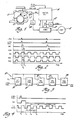
- the preferred embodiment of this invention is described with respect to an eight cylinder diesel engine l0 having a fuel pump l2 rotated thereby for injecting fuel to the individual cylinders.
- the fuel pump l2 is a known form of pump that includes a solenoid energized in timed relationship to the diesel engine position so as to control the timing and quantity of fuel injected into the individual cylinders.
- the diesel engine l0 includes a flywheel l4 having teeth spaced around its periphery at, for example, three degree intervals.
- An electromagnetic sensor l6 is positioned to sense the teeth on the flywheel l4 as it is rotated by the engine crankshaft (not shown).
- the output of the electromagnetic sensor l6 is provided to a squaring amplifier l7 whose output comprises flywheel (FW) pulses that are supplied to a control unit l8 at each three degrees of flywheel rotation.
- Control of the fuel pump l2 to deliver fuel to the diesel engine l0 is provided by the control unit l8 in conjunction with a timer 20.
- the control unit l8 receives inputs from a mass air flow sensor representing the mass air flow into the diesel engine l0 and from an accelerator pedal position sensor representing the position of a conventional operator adjusted accelerator pedal.
- the control unit l8 also receives a once-per-revolution sync pulse at an angular position before top dead centre of one of the engine pistons and a top dead centre signal (TDC) from the timer 20 at each engine piston top dead centre position.
- TDC top dead centre signal
- the sync pulse is generated during each engine rotation by a tooth carried by the flywheel l4 and an associated electromagnetic sensor within the angular range around top dead centre position of a piston wherein the engine speed is symmetrical.
- the once-per-revolution sync pulse is provided by a pulse generator within the fuel pump l2.
- This pulse generator may take the form of two teeth spaced l80° apart rotated with the shaft of the fuel pump l2 and an electromagnetic sensor, similar to the electromagnetic sensor l6, for sensing the passing of the teeth.
- the output of the electromagnetic sensor is then provided to a squaring amplifier 22 which provides the once-per-revolution sync pulse to the control unit l8 and also to the timer 20.
- a single tooth may be provided that is rotated by the shaft of the fuel pump l2 to provide one pulse for each engine cycle or multiple teeth providing a pulse for each engine cylinder.
- the fuel pump l2 generates the sync pulse well ahead of the desired angular range near top dead centre wherein the engine speed is symmetrical so as to avoid irregularities in the position of the sync pulse relative to the engine angular position. These irregularities are caused by factors including drive train lash. Even with this precaution, the generation of the once-per-revolution sync pulse relative to the engine angular position may not be precisely known due to various machining, assembly, and installation tolerances. As will be described, this invention provides for accurate determination of the top dead centre position of each of the pistons in the diesel engine l0 relative to the once-per-revolution sync pulse provided by the fuel pump l2 even though the location of the sync pulse relative to the engine position is not precisely known.
- a signal having a frequency that is a predetermined multiple of the frequency of the flywheel teeth signal is provided to the timer 20 by means of a phase locked loop circuit 24.
- the phase locked loop circuit 24 is conventional and provides for multiplication of the flywheel teeth frequency by means of a divider in its feedback path.
- the operation of the apparatus of Figure l for controlling the input to the fuel pump l2 so as to provide fuel injection timed precisely to engine top dead centre position is illustrated in the timing diagram of Figure 2 w ith reference to the schematic of the timer 20 in Figure 3.
- the timer 20 of Figure 3 is comprised of individual counter circuits 26 through 34 each being clocked by the pulse output of the phase locked loop 24.
- the counter circuits 26 through 34 are each enabled to time or count a predetermined interval based on an engine rotation angle represented by a predetermined number of phase locked loop pulses by an edge trigger provided to its gate input.
- the duration timed or counted by each of the counter circuits 26 through 34 is established by the control unit l8 which periodically sets an engine angular rotation value in terms of a predetermined number of phase locked loop pulses into the respective counter circuit. Additionally, the counter circuits 26 through 34 are selectively set into either (l) a single shot mode wherein the number set therein by the control unit l8 is counted only once in response to a trigger signal or (2) a continuous mode wherein the number set therein by the control unit l8 is repeatedly counted.
- the once-per-revolution sync pulse is generated once each engine revolution by the squaring amplifier 22.
- the counter circuit 26 set in a single shot mode is enabled by the trailing edge of the sync pulse at time t1 to generate an interrupt pulse at its 0 output having a duration from t1 to t2 determined by a predetermined rotational angle defined by a predetermined number of phase locked loop pulses to be counted and which is set therein by the control unit l8.
- the engine angular rotation represented by the interrupt pulse is adaptively adjusted so that its trailing edge is before piston top dead centre within the angular range where the engine speed waveform is symmetrical about top dead centre.
- This trailing edge functions as an interrupt for the program executed by the control unit l8.
- the counter circuit 28 set in a single shot mode is enabled by the trailing edge of the interrupt pulse at time t2 from the counter circuit 26 to generate a KTOP pulse at its 0 output having a duration from t2 to t3 determined by a predetermined number of phase locked loop pulses to be counted and which is set therein by the control unit l8.
- the number of phase locked loop pulses establishing the duration of the KTOP pulse is determined in accordance with this invention so that the trailing edge of the KTOP pulse occurs at the piston top dead centre position.
- the counter circuit 30 set in a continuous mode is initialized by the trailing edge of the KTOP pulse at time t3 from the counter circuit 28.
- the 0 output of the counter circuit 30 thereafter changes state at each 45 degrees of rotation of the diesel engine l0 beginning with a high-to-low transition at the trailing edge of the KTOP pulse.
- the number of phase locked loop pulses permanently set into the counter circuit 30 is the number of pulses in 45 degrees of engine rotation so that the high-to-low transition of the TDC pulses occurs at 90 degree intervals at each piston top dead centre position of the diesel engine l0.
- the counter circuit 32 set in a single shot mode is enabled by the high-to-low transitions of the top dead centre signal from the counter circuit 30 to generate an advance pulse at its 0 output having a duration determined by a predetermined number of phase locked loop pulses representing a desired injection timing angle to be counted and which is set therein by the control unit l8.
- the counter circuit 34 set in a single shot mode is enabled by the trailing edge of the timing signal from the counter circuit 32 to generate a fuel pulse signal at its 0 output having a duration determined by a predetermined number of phase locked loop pulses representing a desired injection fuel quantity. This number is set into the counter circuit 34 by the control unit l8 based on factors including the mass air flow into the diesel engine l0 and the position of the accelerator pedal.
- the timing diagram of Figure 4 illustrates the operation of the subject invention in determining the duration of the KTOP pulse of Figure 2.
- the duration of the KTOP pulse is determined by the number of phase locked loop pulses representing the required angular rotation of the diesel engine l0 from termination of the interrupt pulse at the time t2 to engine top dead centre.
- the control unit l8 functions to measure the time period t d1 to the next flywheel tooth (each tooth being represented by a trailing edge of the output of the FW signal provided by the squaring amplifier l7). As viewed in Figure 4, the next flywheel tooth is sensed at time t4. The control unit l8 then measures the time t d2 to the next flywheel tooth sensed at time t5. The time interval t d2 between times t4 and t5 in conjunction with the angular spacing of the flywheel teeth provide a measure of the instantaneous engine speed.
- the control unit l8 then counts flywheel teeth while monitoring the instantaneous engine speed represented by the time between consecutive flywheel teeth as the engine speed decreases to engine top dead centre position and thereafter increases and until the time t d3 between consecutive flywheel teeth becomes equal to or less than the time t d2 representing matching speeds on each side of top dead centre. From the foregoing information, the precise location of engine top dead centre position relative to the termination of the interrupt pulse at time t2 can be determined.
- the engine top dead centre position relative to the interrupt pulse is equal to the engine angular rotation over the time period t d1 (which can be determined from the engine speed based on the time interval t d2 ) and one-half of the engine angular rotation d4 between the matching engine speed points on each side of top dead centre.
- This value in phase locked loop pulses defines the KTOP pulse duration that is inserted into the timer 20 of Figure 3 by the control unit l8.
- the control unit l8 of Figure l takes the form of a digital computer of standard configuration that includes a central processing unit, a random access memory, a read-only memory, a non-volatile memory, an input/output unit, an analogue-to-digital converter and a clock.
- the operation of the control unit l8 is provided by means of a program permanently stored in the read-only memory and which is repeatedly executed for determining the engine top dead centre position and for controlling the fuel delivered by the fuel pump l2.
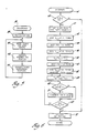
- Figures 5 through 9 are flow diagrams illustrating the operation of the program in carrying out the principles of this invention and for controlling the fuel pump l2.
- step 38 the digital computer provides for initialization. For example, at this step 38, initial values stored in the read-only memory are entered into the random access memory and counters, flags, and timers are initialized.
- This program loop includes a step 40 at which the various inputs to the control unit l8 are read, scaled and saved in memory. These inputs include the mass air signal and the accelerator pedal position.
- a dynamic top dead centre routine is executed at step 42. This dynamic top dead centre routine determines the number of phase locked loop pulses defini ng the duration of the KTOP pulse and also the number of phase locked loop pulses defining the duration of the interrupt pulse provided by the counter circuit 26. This routine will be described in detail with respect to Figure 9.
- the program proceeds to a step 44 where other background routines are executed. These background routines may include, for example, diagnostic routines. Following step 44, the program returns to step 40 where the cycle is repeated.
- the interrupt routine is entered at point 46 and proceeds to a step 48 where the program determines whether the interrupt was in response to a top dead centre signal or the interrupt signal occuring once for each engine revolution. Assuming the interrupt was in response to the interrupt signal, the program proceeds then to step 50 where a once-per-revolution flag is set and the count in a tooth counting register is set to zero. Next the program executes a step 52 where the time represented by the count in a free running timer counter clocked by the control unit l8 clock is stored in memory representing the time t int corresponding to the time t2 of Figures 2 and 4.
- step 54 the program waits until a flywheel tooth signal is detected which occurs at the time t4 of Figure 4.
- the program then proceeds to step 56 where the count in the free running timer is stored in memory representing the time t 1st .
- step 58 the time t d1 representing the difference between the time stored at step 52 and 56 is determined. This time represents the time from the interrupt pulse to the detection of the first tooth.
- the program waits for the detection of the next flywheel tooth.
- the program proceeds to a step 62 where the count in the free running timer is again stored in memory representing the time t 2nd and the tooth counter is incremented.
- the time t d2 between the first two teeth detected after the interrupt pulse is determined from the stored times t 2nd and t 1st . This time in conjunction with the angular spacing of flywheel teeth is representative of the instantaneous engine speed at some angle before top dead centre of the engine piston.
- the program next proceeds to a step 66 to determine whether or not another flywheel tooth has been sensed. If not, the program proceeds to a step 68 where the state of a TDC flag, set upon receipt of the top dead centre signal from the timer 20 of Figure 3, is sensed. If reset, the program returns to step 66. This cycle is repeated until a flywheel tooth is sensed at which time the program proceeds to a step 70 to increment the tooth counter.
- step 70 the program proceeds to step 68 and the steps 66, 68 and 70 are repeated as above described until a top dead centre signal (the falling edge of the output of the counter circuit 30) is sensed indicating the piston is substantially at top dead centre.
- a top dead centre signal the falling edge of the output of the counter circuit 30
- the program proceeds directly to a step 72 where a top dead centre routine is executed. From step 72, the interrupt routine of Figure 6 returns to the background loop of Figure 5.
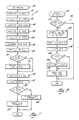
- step 72 of Figure 6 The top dead centre routine of step 72 of Figure 6 is illustrated in Figure 7.
- This routine is entered at step 74 and proceeds to a step 76 where the program waits for the next flywheel tooth.
- the program proceeds to a step 78 whe re the stored time t 1st is set equal to the count in the free running timer. Thereafter, the tooth counter is incremented at step 80.
- the program again waits for the next flywheel tooth.
- the stored time t 2nd is set at step 84 equal to the count in the free running timer and the tooth counter is incremented at step 86.
- times t 1st and t 2nd are saved in memory.
- step 90 the program determines whether or not the once-per-revolution flag is set. Since it was set at step 50, the program proceeds to a step 92 where a match flywheel time routine is executed. This routine is illustrated in Figure 8.
- the match flywheel time routine is entered at point 94 and then proceeds to a step 96 where the state of a last information flag is sampled.
- the flag indicates the last determined value of the duration of the KTOP pulse has been incorporated into a filtered signal. If the flag is reset, the program proceeds to a step 98 to determine whether or not the engine speed is within a predetermined range. This speed is determined from the times t 1st and t 2nd saved at step 88, the difference between those times representing the time between consecutive flywheel teeth and therefore the instantaneous engine speed.
- step l00 the stored time t 1st is set equal to the stored time t 2nd . Thereafter, the program waits for the next flywheel tooth at step l02.
- the stored time t 2nd is set equal to the count in the free running timer after which the time interval t d3 equal to the difference between t 2nd and t 1st is determined at step l06.
- the time t d3 is the time between two consecutive flywheel teeth and therefore is representative of the instantaneous flywheel speed.
- this instantaneous speed is compared with the engine speed previously recorded before top dead centre represented by the time t d2 stored at step 64 of Figure 6. If t d3 is greater than t d2 indicating that the engine speed after top dead centre is less than the engine speed represented by the time t d2 , the program proceeds to a step ll0 where the tooth counter is incremented.
- the steps l00 through ll0 are continually repeated to monitor the instantaneous engine speed until the engine speed becomes equal to or greater than the engine speed represented by the time t d2 measured before piston top dead centre.
- the program proceeds to a step lll where a stored value C4 is set equal to the flywheel tooth count in the tooth counter.
- C4 is representative of the angular rotation in terms of a number of flywheel teeth between the matching speeds represented by the times t d2 and t d3 .
- step ll2 the time t d1 and the tooth count C4 are saved in respective memory locations. Thereafter at step ll4 the last information flag is set to indicate that new information has been accumulated to be averaged into the value of the KTOP pulse.
- a KTOP filt value determined as will be described is set into the (KTOP) counter circuit 28 of Figure 3. Thereafter, the once-per-revolution flag previously set at step 50 is reset at step ll8.
- step 96 If at step 96 the last information flag was set indicating that the last sensed information had not been incorporated in KTOP filt value, or if the engine speed was not in the predetermined range at step 98, the prog ram proceeds from those steps directly to the step ll6.
- step l20 the program calculates the flywheel speed based on the times l 1st and t 2nd stored at step 88.
- step l22 the program determines the injection timing and the quantity of fuel required for the particular engine operating condition. For example, at this step, the quantity of fuel may be determined based on the accelerator pedal position and the mass air flow into the engine both of which were measured and stored at step 40 of the background loop routine of Figure 5.
- the program determines whether or not the engine speed determined at step l20 is within the desired speed range for determining the engine top dead centre position. As previously indicated, the speed range is substantially at the idle speed wherein the instantaneous engine speed is substantially symmetrical about the engine top dead centre positions. If the engine is outside of the desired speed range, the program proceeds to a step l26 where the once-per-revolution interrupt is disabled. If at step l24 it is determined that the engine speed is within the desired range, the program proceeds to a step l28 where the once-per-revolution interrupt is enabled. Following either of the steps l26 or l28, the program exits the top dead centre routine after which the program returns from the interrupt routine of Figure 6 to the background loop routine of Figure 5.
- the values of t d1 and C4 determined therein are utilized in the dynamic top dead centre routine of step 42 in the background loop routine of Figure 5 for determining the value of the KTOP pulse duration that establishes the top dead centre position of the diesel engine l0.
- the dynamic top dead centre routine 42 is entered at step l30 and proceeds to a step l32 where the last information flag is sampled to determine whether or not the latest information determined in the interrupt routine has been incorporated into the average KTOP value. If the flag is set indicating that there is new information not yet used, the program proceeds to a step l34 where the value of time t d1 and tooth count C4 are converted to phase locked loop pulses.
- the value of time t d1 is converted to a number of phase locked loop pulses d1 representing the angular rotation of the diesel engine l0 over the time period t d1 at the engine speed based on the tooth period t d2 determined at step 64 of the interrupt routine of Figure 6.
- C4 is converted to a number of phase locked loop pulses d4 based on the multiplication factor of the phase locked loop circuit 24 of Figure l.
- the program next proceeds to a step l36 where the value of KTOP is determined by summing the phase locked loop pulses d1 with an empirically determined fraction, such as one-half, of the phase locked loop pulses d4. This represents the engine angular rotation from the termination of the interrupt pulse of the counter circuit 26 to engine top dead centre position.
- the top dead centre position of the engine is accurately determined relative to the once-per-revolution sync pulse provided by the fuel pump l2 even though the location of the once- per-revolution sync pulses relative to engine rotational position is not precisely known.
- the value of the duration of KTOP is a filtered value of a number of KTOP values determined as above described. This filtered value is determined at step l38 where the latest value determined is inco rporated into the filtered value KTOP filt which is inserted into the (KTOP) counter circuit 28 at step ll6 of Figure 8.
- the program next proceeds to a step l40 where the value of C4, which is the number of flywheel teeth counted between the matching speed points represented by the times t d2 and t d3 , is compared to a constant such as 4 or, in another embodiment, a range such that 4 ⁇ ⁇ C4 ⁇ ⁇ 8.
- C4 is selected such that the matching speed points always occur in the prescribed angular range around top dead centre wherein the engine speed waveform is symmetrical. For example, if the value of C4 is greater than the constant, the program proceeds to a step l42 where the number of phase locked loop pulses defining the duration of the interrupt pulse generated by the counter circuit 26 is increased by the number of phase locked loop pulses per flywheel tooth.
- the engine angular rotation C4 By increasing the interrupt pulse by an amount corresponding to the period on one flywheel tooth, the engine angular rotation C4 will be reduced by one or two teeth during the next determination of KTOP. In this manner, the value of C4 will be adjusted so that t2 occurs within the desired engine angular range around piston top dead centre where the engine speed waveform is symmetrical about top dead centre.
- the value of the count defining the interrupt pulse may be decreased if C4 was less than the constant (or range) so that the value of C4 is adaptively adjusted in either direction so as to equal the constant or be within a prescribed range.
- step l42 From step l42 or from step l40 if the value of C4 is equal to or less than the constant, the program proceeds to a step l44 where the last information flag is reset to indicate that the last determined information for establishing the value of KTOP has been utilized.
- the program will bypass the dynamic top dead centre routine of Figure 9 by exiting the routine from step l32.
- step 48 when the interrupt routine is initiated by a top dead centre transition of the top dead centre pulse from the counter circuit 30, the program proceeds directly from step 48 to step 72 where the top dead centre routine of step 72 is executed.
- This routine illustrated in Figure 7 provides for the determination of the injection timing and duration to be inserted into the fuel timer of counter circuit 34 and the advance timer of counter circuit 32 to provide for control of the fuel injected by the fuel pump l2.
- the top dead centre position of each cylinder of the engine relative to a reference pulse whose position is not precisely known may be accurately determined during engine operation to enable precise timing and metering of fuel to the diesel engine l0.
- top dead centre of each piston can be determined by alternative methods, phase locked loop pulses may be counted instead of flywheel teeth or clock pulses, or the phase locked loop pulses may be eliminated.
- the various intervals are based on time, converted to angles based on engine speed and later converted back to time based on engine speed for use in establishing top dead centre and fuel injection timing and duration based thereon.
- the tooth count C4 to the matching speed point may be adjusted by the fraction (t d2 - t d3 )/(t d5 - t d3 ) where t d5 is the flywheel teeth period immediately preceding the period t d3 .
Landscapes
- Engineering & Computer Science (AREA)
- Chemical & Material Sciences (AREA)
- Combustion & Propulsion (AREA)
- Mechanical Engineering (AREA)
- General Engineering & Computer Science (AREA)
- Physics & Mathematics (AREA)
- General Physics & Mathematics (AREA)
- Combined Controls Of Internal Combustion Engines (AREA)
- Electrical Control Of Air Or Fuel Supplied To Internal-Combustion Engine (AREA)
- Testing Of Engines (AREA)
Applications Claiming Priority (2)
| Application Number | Priority Date | Filing Date | Title |
|---|---|---|---|
| US855653 | 1986-04-25 | ||
| US06/855,653 US4653315A (en) | 1986-04-25 | 1986-04-25 | Engine top dead center locating method |
Publications (3)
| Publication Number | Publication Date |
|---|---|
| EP0242994A2 true EP0242994A2 (fr) | 1987-10-28 |
| EP0242994A3 EP0242994A3 (en) | 1988-04-13 |
| EP0242994B1 EP0242994B1 (fr) | 1991-12-18 |
Family
ID=25321776
Family Applications (1)
| Application Number | Title | Priority Date | Filing Date |
|---|---|---|---|
| EP87302455A Expired EP0242994B1 (fr) | 1986-04-25 | 1987-03-23 | Appareil de détermination du point mort haut dans un moteur |
Country Status (5)
| Country | Link |
|---|---|
| US (1) | US4653315A (fr) |
| EP (1) | EP0242994B1 (fr) |
| JP (1) | JPH0678967B2 (fr) |
| CA (1) | CA1252540A (fr) |
| DE (1) | DE3775259D1 (fr) |
Cited By (2)
| Publication number | Priority date | Publication date | Assignee | Title |
|---|---|---|---|---|
| EP0342508A1 (fr) * | 1988-05-16 | 1989-11-23 | Siemens Aktiengesellschaft | Procédé pour la génération d'impulsions de déclenchement |
| RU2473876C1 (ru) * | 2011-06-08 | 2013-01-27 | ФЕДЕРАЛЬНОЕ ГОСУДАРСТВЕННОЕ ВОЕННОЕ ОБРАЗОВАТЕЛЬНОЕ УЧРЕЖДЕНИЕ ВЫСШЕГО ПРОФЕССИОНАЛЬНОГО ОБРАЗОВАНИЯ "ВОЕННАЯ АКАДЕМИЯ ТЫЛА И ТРАНСПОРТА имени Генерала армии А.В. Хрулева" | Способ диагностирования дизелей на основе анализа временных параметров рабочего цикла |
Families Citing this family (10)
| Publication number | Priority date | Publication date | Assignee | Title |
|---|---|---|---|---|
| US4852536A (en) * | 1987-12-11 | 1989-08-01 | Outboard Marine Corporation | Trigger system for ignition system for internal combustion engines |
| US5311771A (en) * | 1992-03-30 | 1994-05-17 | Caterpillar Inc. | Method for determining the rotational position of a crankshaft of an internal combustion engine |
| FR2711185B1 (fr) * | 1993-10-12 | 1996-01-05 | Inst Francais Du Petrole | Système d'acquisition et de traitement instantané de données pour le contrôle d'un moteur à combustion interne. |
| US5551184A (en) * | 1994-10-03 | 1996-09-03 | Grosse; Charles A. | Fishing rod butt pad |
| JP4179815B2 (ja) * | 2002-06-25 | 2008-11-12 | マツダ株式会社 | テスト対象エンジンの圧縮上死点検出装置 |
| JP4281391B2 (ja) * | 2003-03-31 | 2009-06-17 | アイシン・エィ・ダブリュ株式会社 | 回転角検出装置及び回転角検出方法 |
| US7680648B2 (en) * | 2004-09-30 | 2010-03-16 | Google Inc. | Methods and systems for improving text segmentation |
| US20080173079A1 (en) * | 2006-12-27 | 2008-07-24 | Caterpillar Inc. | Method for detecting engine rotation direction |
| US9243571B2 (en) | 2014-01-22 | 2016-01-26 | Deere & Company | Finding top dead center for a reciprocating piston |
| US9562823B2 (en) | 2014-01-22 | 2017-02-07 | Deere & Company | Determining cylinder health in a reciprocating piston engine |
Family Cites Families (5)
| Publication number | Priority date | Publication date | Assignee | Title |
|---|---|---|---|---|
| GB2018067B (en) * | 1978-03-31 | 1982-05-19 | Caterpillar Tractor Co | Timing method and device |
| US4384480A (en) * | 1980-02-14 | 1983-05-24 | General Motors Corporation | Method and apparatus for accurately locating piston top dead center position by a microwave energy technique |
| JPS5749026A (en) * | 1980-09-09 | 1982-03-20 | Nissan Motor Co Ltd | Crank position signal adjusting device |
| JPS57139637A (en) * | 1981-02-23 | 1982-08-28 | Nissan Motor Co Ltd | Top-and-bottom dead point signal compensating method |
| US4520658A (en) * | 1983-12-01 | 1985-06-04 | General Motors Corporation | Method of locating engine top dead center position |
-
1986
- 1986-04-25 US US06/855,653 patent/US4653315A/en not_active Expired - Lifetime
-
1987
- 1987-01-20 CA CA000527681A patent/CA1252540A/fr not_active Expired
- 1987-03-23 DE DE8787302455T patent/DE3775259D1/de not_active Expired - Lifetime
- 1987-03-23 EP EP87302455A patent/EP0242994B1/fr not_active Expired
- 1987-04-24 JP JP62101698A patent/JPH0678967B2/ja not_active Expired - Lifetime
Cited By (3)
| Publication number | Priority date | Publication date | Assignee | Title |
|---|---|---|---|---|
| EP0342508A1 (fr) * | 1988-05-16 | 1989-11-23 | Siemens Aktiengesellschaft | Procédé pour la génération d'impulsions de déclenchement |
| US5019988A (en) * | 1988-05-16 | 1991-05-28 | Siemens Aktiengesellschaft | Method for generating trigger pulses |
| RU2473876C1 (ru) * | 2011-06-08 | 2013-01-27 | ФЕДЕРАЛЬНОЕ ГОСУДАРСТВЕННОЕ ВОЕННОЕ ОБРАЗОВАТЕЛЬНОЕ УЧРЕЖДЕНИЕ ВЫСШЕГО ПРОФЕССИОНАЛЬНОГО ОБРАЗОВАНИЯ "ВОЕННАЯ АКАДЕМИЯ ТЫЛА И ТРАНСПОРТА имени Генерала армии А.В. Хрулева" | Способ диагностирования дизелей на основе анализа временных параметров рабочего цикла |
Also Published As
| Publication number | Publication date |
|---|---|
| EP0242994B1 (fr) | 1991-12-18 |
| CA1252540A (fr) | 1989-04-11 |
| DE3775259D1 (de) | 1992-01-30 |
| JPH0678967B2 (ja) | 1994-10-05 |
| US4653315A (en) | 1987-03-31 |
| EP0242994A3 (en) | 1988-04-13 |
| JPS62267639A (ja) | 1987-11-20 |
Similar Documents
| Publication | Publication Date | Title |
|---|---|---|
| RU2082015C1 (ru) | Способ последовательного впрыскивания топлива | |
| US5056360A (en) | Selection of velocity interval for power stroke acceleration measurements | |
| JP2927600B2 (ja) | 機関速度および位置を決定するための単一センサ装置および方法 | |
| US4782692A (en) | Engine crankshaft position sensor | |
| CA1222317A (fr) | Mesurage du taux de compression et de la puissance developpee dans un cylindre de moteur thermique | |
| US4691288A (en) | Torque sensor for internal-combustion engine | |
| EP0242994B1 (fr) | Appareil de détermination du point mort haut dans un moteur | |
| US4535406A (en) | Fuel distribution control for an internal combustion engine | |
| US4358828A (en) | Engine speed measuring system | |
| JPH01240754A (ja) | エンジン空気流量の測定方法及び装置 | |
| US5860406A (en) | Engine timing apparatus and method of operating same | |
| EP0591283A1 (fr) | Procede pour determiner la position en rotation d'un vilebrequin d'un moteur a combustion interne. | |
| US4254744A (en) | Method and apparatus for measuring air quantity in relation to engine speed | |
| US6334094B1 (en) | Engine speed calculation apparatus | |
| CA1216672A (fr) | Methode pour la determination du point mort haut d'un moteur | |
| US4160429A (en) | Electronically controlled fuel injection system for internal combustion engines | |
| US4520449A (en) | Phase angle detector | |
| US5172669A (en) | Engine control system | |
| US6560558B2 (en) | Engine speed calculating apparatus | |
| JP2763294B2 (ja) | 内燃機関用制御器の入力信号検出装置 | |
| US20020189588A1 (en) | Control system for internal combustion engine | |
| JP3011353B2 (ja) | 多気筒エンジンの回転変動率の測定方法 | |
| GB2052071A (en) | Engine Speed Measuring System | |
| JPH0117650Y2 (fr) | ||
| JPH0117649Y2 (fr) |
Legal Events
| Date | Code | Title | Description |
|---|---|---|---|
| PUAI | Public reference made under article 153(3) epc to a published international application that has entered the european phase |
Free format text: ORIGINAL CODE: 0009012 |
|
| AK | Designated contracting states |
Kind code of ref document: A2 Designated state(s): DE FR GB |
|
| PUAL | Search report despatched |
Free format text: ORIGINAL CODE: 0009013 |
|
| AK | Designated contracting states |
Kind code of ref document: A3 Designated state(s): DE FR GB |
|
| 17P | Request for examination filed |
Effective date: 19880524 |
|
| 17Q | First examination report despatched |
Effective date: 19900827 |
|
| GRAA | (expected) grant |
Free format text: ORIGINAL CODE: 0009210 |
|
| AK | Designated contracting states |
Kind code of ref document: B1 Designated state(s): DE FR GB |
|
| REF | Corresponds to: |
Ref document number: 3775259 Country of ref document: DE Date of ref document: 19920130 |
|
| ET | Fr: translation filed | ||
| PLBE | No opposition filed within time limit |
Free format text: ORIGINAL CODE: 0009261 |
|
| STAA | Information on the status of an ep patent application or granted ep patent |
Free format text: STATUS: NO OPPOSITION FILED WITHIN TIME LIMIT |
|
| 26N | No opposition filed | ||
| PGFP | Annual fee paid to national office [announced via postgrant information from national office to epo] |
Ref country code: GB Payment date: 19940228 Year of fee payment: 8 |
|
| PGFP | Annual fee paid to national office [announced via postgrant information from national office to epo] |
Ref country code: FR Payment date: 19940325 Year of fee payment: 8 |
|
| PGFP | Annual fee paid to national office [announced via postgrant information from national office to epo] |
Ref country code: DE Payment date: 19940510 Year of fee payment: 8 |
|
| PG25 | Lapsed in a contracting state [announced via postgrant information from national office to epo] |
Ref country code: GB Effective date: 19950323 |
|
| GBPC | Gb: european patent ceased through non-payment of renewal fee |
Effective date: 19950323 |
|
| PG25 | Lapsed in a contracting state [announced via postgrant information from national office to epo] |
Ref country code: FR Free format text: LAPSE BECAUSE OF NON-PAYMENT OF DUE FEES Effective date: 19951130 |
|
| PG25 | Lapsed in a contracting state [announced via postgrant information from national office to epo] |
Ref country code: DE Effective date: 19951201 |
|
| REG | Reference to a national code |
Ref country code: FR Ref legal event code: ST |