EP0242844B1 - Spiegel mit variabler Oberfläche für ein optisches Wellenanpassungssystem - Google Patents
Spiegel mit variabler Oberfläche für ein optisches Wellenanpassungssystem Download PDFInfo
- Publication number
- EP0242844B1 EP0242844B1 EP87105825A EP87105825A EP0242844B1 EP 0242844 B1 EP0242844 B1 EP 0242844B1 EP 87105825 A EP87105825 A EP 87105825A EP 87105825 A EP87105825 A EP 87105825A EP 0242844 B1 EP0242844 B1 EP 0242844B1
- Authority
- EP
- European Patent Office
- Prior art keywords
- transducer
- plate
- mirror
- electrode
- contact
- Prior art date
- Legal status (The legal status is an assumption and is not a legal conclusion. Google has not performed a legal analysis and makes no representation as to the accuracy of the status listed.)
- Expired - Lifetime
Links
- 230000003287 optical effect Effects 0.000 title claims description 9
- 230000003044 adaptive effect Effects 0.000 title description 2
- 229910052751 metal Inorganic materials 0.000 claims abstract description 5
- 239000002184 metal Substances 0.000 claims abstract description 5
- ZOKXTWBITQBERF-UHFFFAOYSA-N Molybdenum Chemical compound [Mo] ZOKXTWBITQBERF-UHFFFAOYSA-N 0.000 claims description 6
- 239000000919 ceramic Substances 0.000 claims description 6
- 229910052750 molybdenum Inorganic materials 0.000 claims description 5
- 239000011733 molybdenum Substances 0.000 claims description 5
- PNEYBMLMFCGWSK-UHFFFAOYSA-N aluminium oxide Inorganic materials [O-2].[O-2].[O-2].[Al+3].[Al+3] PNEYBMLMFCGWSK-UHFFFAOYSA-N 0.000 claims description 4
- 229910010293 ceramic material Inorganic materials 0.000 claims 1
- 239000000463 material Substances 0.000 claims 1
- 238000010586 diagram Methods 0.000 description 2
- 241000287107 Passer Species 0.000 description 1
- HIGRAKVNKLCVCA-UHFFFAOYSA-N alumine Chemical compound C1=CC=[Al]C=C1 HIGRAKVNKLCVCA-UHFFFAOYSA-N 0.000 description 1
- 229910052782 aluminium Inorganic materials 0.000 description 1
- XAGFODPZIPBFFR-UHFFFAOYSA-N aluminium Chemical compound [Al] XAGFODPZIPBFFR-UHFFFAOYSA-N 0.000 description 1
- 239000012530 fluid Substances 0.000 description 1
- 239000011521 glass Substances 0.000 description 1
- PCHJSUWPFVWCPO-UHFFFAOYSA-N gold Chemical compound [Au] PCHJSUWPFVWCPO-UHFFFAOYSA-N 0.000 description 1
- 239000010931 gold Substances 0.000 description 1
- 229910052737 gold Inorganic materials 0.000 description 1
- 238000010438 heat treatment Methods 0.000 description 1
- 229910000679 solder Inorganic materials 0.000 description 1
- 230000003068 static effect Effects 0.000 description 1
- XLYOFNOQVPJJNP-UHFFFAOYSA-N water Substances O XLYOFNOQVPJJNP-UHFFFAOYSA-N 0.000 description 1
Images

Classifications
-
- G—PHYSICS
- G02—OPTICS
- G02B—OPTICAL ELEMENTS, SYSTEMS OR APPARATUS
- G02B26/00—Optical devices or arrangements for the control of light using movable or deformable optical elements
- G02B26/06—Optical devices or arrangements for the control of light using movable or deformable optical elements for controlling the phase of light
Definitions
- the present invention relates to a mirror with a modular, that is to say deformable, surface.
- This mirror finds its use in a wavefront adapter optical system. It is of a type as defined in the preamble of claim 1.
- the plate is made of glass, of circular shape and coated on one of its faces with a reflective aluminum layer; the rigid part is a thick piezoelectric ceramic disc.
- N electrically conductive elements are regularly distributed over a first flat face of the disc, these elements being provided with connection wires crossing the thickness of the disc.
- An electrically conductive layer is deposited on the second plane face of the disc. The first flat face of the disc is fixed on the plate, on the opposite side of its reflecting face.
- the disc, the conductive elements and the conductive layer form a piezoelectric system comprising N pairs of electrodes, each pair comprising one of said conductive elements and the conductive layer which forms a common electrode.
- a difference in electrical potential is applied to a pair of electrodes, a local deformation of the plate is caused in the vicinity of the conductive element of this pair of electrodes.
- mirrors with a deformable surface can be used to adapt the phase of different portions of the section of a laser beam so as to obtain after beam concentration maximum energy on a target.
- the laser beam can then be reflected successively on two mirrors with deformable surface, before being focused on the target, part of the laser energy returned by the target being received by a processing circuit through a receiver.
- the different pairs of electrodes of the first mirror called the modulation mirror, are supplied by an electric source respectively at frequencies different from one another, so as to modulate N portions of the section of the laser beam at these different frequencies.
- the second mirror called the correction mirror
- the processing circuit picks up through the receiver the frequencies characteristic of the N portions of the beam, so as to control the electrical supply of the corresponding electrodes of the correction mirror.
- each pair of electrodes of the first mirror is supplied with an electric voltage whose frequency results from a linear combination of frequencies, the N combinations being different from each other.
- the principle of this so-called modal feeding is exposed in the article "Adaptive optic modal control” (JP Gaffard et al) "Cleo ′ 84" "Conference on Lasers and Electro-optics” June 19-22, 1984, pages 1 to 10 and 1 to 6.
- the known deformable surface mirror described above, has a drawback because each transducer can only operate in a determined frequency range.
- a complete symmetry of the modular structure is achieved so that all the transducers can be stressed in a very wide frequency band only limited by the first longidutinal natural frequency of the transducers. It is then possible to make modal combinations of the different modulation frequencies.
- the present invention relates to a mirror as defined in claim 1.
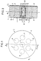
- a mirror 1 with a deformable surface is shown.
- the mirror 1 comprises a circular molybdenum plate 2, one main face 3 of which is polished to form the reflecting surface of the mirror.
- the mirror 1 further comprises a rigid part 4 also made of molybdenum, having the general shape of a cylinder of revolution with a diameter equal to that of the plate 2.
- the part 4 comprises seven cylindrical openings 5 to 11, identical to each other, and the axes of which are perpendicular to the bases of the cylinder forming the part 4.
- these seven openings are uniformly distributed over the surface of said bases: a central opening 5 is arranged along the axis 14 of the part 4, the other 6 openings being arranged around the breakthrough 5, their axes being placed at the vertices of a hexagon centered on the axis of the cylinder, so that the distance of the axes of these six other breakthroughs to the axis 14 is equal to the side of the hexagon.
- the main face of the plate 2, opposite the reflecting face 3 is fixed over the entire flat surface of a base 12 of the part 4. This fixing can be carried out for example by a solder with gold.
- a piezoelectric transducer 13 Inside each of these openings is arranged coaxially a piezoelectric transducer 13 of cylindrical shape. Between a flat base of the transducer 13 and the plate 2 is disposed a hemispherical pusher 15, made of alumina, the curved surface of which is in contact with a central zone 16 of the part 17 of the plate 2 opposite the transducer 13. The flat surface of the pusher 15 is in contact with the transducer 13.
- the breakthrough 5 is closed, on the base 18 of the part 4, opposite the plate 2, by a cap 19 made of molybdenum provided with a flat bottom 20 situated substantially along the plane of the base 18.
- This cap 19 can be fixed on the part 4 inside the breakthrough 5 for example by screwing.
- a hemispherical alumina pusher 21 identical to the pusher 15.
- the curved face of the pusher 21 is in contact with a central zone of the bottom 20 of the cap 19, while the face plane of the pusher 21 is in contact with the transducer 13.
- the mirror plungers are provided with an axial orifice 22, 23.
- the flat bottoms 20 of the caps 19 are provided with an axial orifice 24.
- the transducer 13 has two electrodes. On one of these electrodes is fixed a connection wire 25 which passes through the orifices 22 and 24.
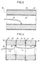
- FIGS. 3 and 4 showing two embodiments of a transducer capable of being used to produce a mirror with a deformable surface, of the type of that illustrated in FIGS. 1 and 2.
- FIG. 3 shows a transducer 26 comprising a tubular block 27 made of piezoelectric ceramic. On the outer and inner cylindrical surfaces of the block 27 are deposited conductive layers 28 and 29 forming the electrodes of the transducer. In the internal volume of block 27 is visible an electrical connection wire 30 one end of which is welded to the inner layer 29. The other end of the connection wire 30 passes through the orifice of the cap and that of the pusher in contact with this cap as explained above. The outer layer 28 is in contact with the wall of the opening in which the transducer is housed. It can therefore be seen that the mass of the part 4 is connected to an electrode of each of the transducers, the connection wire as 30 being connected to the other electrode of the transducer.
- FIG. 4 shows a transducer 31 comprising an axial stack of tubular blocks 32, 33, 34 in piezoelectric ceramic.
- Conductive layers 35, 36, 37, 38 are arranged on the flat faces of these blocks.
- the layers 36 and 38 have flanges 39 and 40 on the internal surface of the blocks. These flanges are interconnected by a connection wire 41, on which is welded a connection wire 42 passing through the orifice of the cap and of the corresponding pusher.
- the layers 35 and 37 have flanges 43 and 44 on the external surface of the blocks, these flanges being in contact with the mass of the part 4 by the wall of the opening in which the transducer 31 is disposed. In this case also, the mass of the part 4 is connected to an electrode of each of the transducers.
- the transducer 13 and the two pushers 15 and 21 are arranged in the opening 5 by screwing the cap 19 so that the plate 2 and the bottom 20 of the cap 19 exert a slight pressure on the pushers , this pressure being transmitted to the transducer by these pushers.
- this pressure is the same for all the transducers of the mirror.
- the thickness of the bottom 20 of the cap 19 is determined so that the deformation curve of this bottom as a function of the axial pressure is substantially identical to the deformation curve of the part 17 of the plate 2.
- the device shown in Figures 1 and 2 operates as follows.
- an electrical voltage is applied between the electrodes of the transducer 13, that is to say between the connection wire 25 and the mass of the part 4, the part 17 of the plate is deformed.
- the central point of part 17 has maximum deformation along the axis of the transducer, while the circular periphery of this part 17 fixed on the part 4 does not deform.
- the profile of the deformation can be assimilated to a Gaussian.
- the gain and phase response curves as a function of frequency, plotted for the different transducers mounted in their housings are substantially identical to each other.
- each transducer mounted in its housing it was advantageous for each transducer mounted in its housing to have static and dynamic symmetry with respect to the median plane 45 (see FIG. 2) parallel to the plane faces of the part 4 and cutting it in the middle of its thickness. This is the reason why the pushers 15 in contact with the plate 2 are provided with axial orifices 23, like the pushers 21 in contact with the cap 21. If this symmetry is respected, it is easier to determine the dimensions to give to the mirror, in each particular case, so that the gain and the phase remain substantially constant in a frequency interval as large as possible. This is an important advantage when it is desired to use the mirror with a modal power supply to produce an optical system that adapts the wavefront.
- FIG. 5 shows a diagram of a wavefront adapter optical system.
- This system comprises a generator (not shown) emitting a laser beam 46 which is received by a modulation mirror 47 according to the invention with seven transducers, the mirror 47 being connected to the output of an electrical power source 48.
- the beam 49 returned by the mirror 47 is received by a correction mirror 50 with deformable surface, of the conventional type, connected to the output of an electrical supply circuit 51.
- the beam 52 returned by the mirror 50 is divided into two parts by a partially reflecting optical plate 53. The smallest of these parts is reflected in a beam 54 concentrated by an optical system 55 on the photosensitive surface of a receiver 56 electrically connected to the input of the circuit 51.
- the beam 57 passing through the blade 53 is used for example to perform heat treatment.
- the seven transducers of the mirror 47 are electrically powered by the source 48, respectively according to seven linear combinations of frequencies which are for example between 30 and 60 kHz, so as to define seven different portions of the laser beam.
- the mirror 50 also includes seven transducers acting on these seven portions.
- the receiver 56 is capable of effectively recognizing these seven portions and of controlling the circuit 51 to correct the phase of each of the seven portions so as to obtain maximum energy for the beam 57. This recognition can be carried out without ambiguity since the curves of response of the different mirror motors are identical in the modulation frequency range.
- the mirror with a deformable surface according to the invention has the advantage of being able to be effectively cooled, if necessary, by circulating a fluid, for example water, in pipes (not shown) arranged in the room. rigid under the surface of the reflective plate.
- a fluid for example water
Landscapes
- Physics & Mathematics (AREA)
- General Physics & Mathematics (AREA)
- Optics & Photonics (AREA)
- Mechanical Light Control Or Optical Switches (AREA)
- Optical Elements Other Than Lenses (AREA)
- Mounting And Adjusting Of Optical Elements (AREA)
- Telescopes (AREA)
- Optical Couplings Of Light Guides (AREA)
- Laser Beam Printer (AREA)
- Optical Communication System (AREA)
Claims (8)
Priority Applications (1)
| Application Number | Priority Date | Filing Date | Title |
|---|---|---|---|
| AT87105825T ATE64660T1 (de) | 1986-04-23 | 1987-04-21 | Spiegel mit variabler oberflaeche fuer ein optisches wellenanpassungssystem. |
Applications Claiming Priority (2)
| Application Number | Priority Date | Filing Date | Title |
|---|---|---|---|
| FR8605866 | 1986-04-23 | ||
| FR8605866A FR2597983B1 (fr) | 1986-04-23 | 1986-04-23 | Miroir a surface modulable pour systeme optique adaptateur de front d'onde |
Publications (2)
| Publication Number | Publication Date |
|---|---|
| EP0242844A1 EP0242844A1 (de) | 1987-10-28 |
| EP0242844B1 true EP0242844B1 (de) | 1991-06-19 |
Family
ID=9334534
Family Applications (1)
| Application Number | Title | Priority Date | Filing Date |
|---|---|---|---|
| EP87105825A Expired - Lifetime EP0242844B1 (de) | 1986-04-23 | 1987-04-21 | Spiegel mit variabler Oberfläche für ein optisches Wellenanpassungssystem |
Country Status (6)
| Country | Link |
|---|---|
| EP (1) | EP0242844B1 (de) |
| AT (1) | ATE64660T1 (de) |
| DE (1) | DE3770859D1 (de) |
| ES (1) | ES2023843B3 (de) |
| FR (1) | FR2597983B1 (de) |
| GR (1) | GR3002762T3 (de) |
Cited By (1)
| Publication number | Priority date | Publication date | Assignee | Title |
|---|---|---|---|---|
| EP1923730A1 (de) | 2006-11-17 | 2008-05-21 | Funai Electric Co., Ltd. | Verformbarer Spiegel |
Families Citing this family (1)
| Publication number | Priority date | Publication date | Assignee | Title |
|---|---|---|---|---|
| DE3808150A1 (de) * | 1988-03-11 | 1989-09-28 | Diehl Gmbh & Co | Moduliereinrichtung fuer eine verformbare spiegelplatte |
Family Cites Families (4)
| Publication number | Priority date | Publication date | Assignee | Title |
|---|---|---|---|---|
| US3828143A (en) * | 1972-06-21 | 1974-08-06 | Us Navy | Piezoelectric end capped cylinder assembly for use to the radial-mode resonance frequency |
| DE2447219A1 (de) * | 1974-10-03 | 1976-04-08 | Philips Patentverwaltung | Piezoelektrisches uebertragungselement |
| US3967899A (en) * | 1974-12-30 | 1976-07-06 | Hughes Aircraft Company | Method and apparatus for maintaining far field spatial coherency in electromagnetic transmitting systems |
| US4130624A (en) * | 1977-11-03 | 1978-12-19 | Ohaus Scale Corporation | Piezo-electric disc mounting methods and apparatus |
-
1986
- 1986-04-23 FR FR8605866A patent/FR2597983B1/fr not_active Expired - Lifetime
-
1987
- 1987-04-21 EP EP87105825A patent/EP0242844B1/de not_active Expired - Lifetime
- 1987-04-21 ES ES87105825T patent/ES2023843B3/es not_active Expired - Lifetime
- 1987-04-21 DE DE8787105825T patent/DE3770859D1/de not_active Expired - Lifetime
- 1987-04-21 AT AT87105825T patent/ATE64660T1/de not_active IP Right Cessation
-
1991
- 1991-09-19 GR GR91401373T patent/GR3002762T3/el unknown
Cited By (1)
| Publication number | Priority date | Publication date | Assignee | Title |
|---|---|---|---|---|
| EP1923730A1 (de) | 2006-11-17 | 2008-05-21 | Funai Electric Co., Ltd. | Verformbarer Spiegel |
Also Published As
| Publication number | Publication date |
|---|---|
| ES2023843B3 (es) | 1992-02-16 |
| EP0242844A1 (de) | 1987-10-28 |
| FR2597983B1 (fr) | 1990-03-23 |
| DE3770859D1 (de) | 1991-07-25 |
| FR2597983A1 (fr) | 1987-10-30 |
| GR3002762T3 (en) | 1993-01-25 |
| ATE64660T1 (de) | 1991-07-15 |
Similar Documents
| Publication | Publication Date | Title |
|---|---|---|
| EP0209449B1 (de) | Deformierbarer spiegel | |
| JP2944692B2 (ja) | 半導体装置構造 | |
| KR0168898B1 (ko) | 쌍방향 전송용 광 모듈 | |
| US5815626A (en) | Optical transmission device, solid state laser device, and laser beam processing device | |
| GB2294126A (en) | Optical transmission and solid state laser devices using graded index optical fibre | |
| CA2171590A1 (en) | Method and device for focusing laser beam | |
| EP0939893A1 (de) | Miniaturisiertes photoakustisches spektrometer | |
| JPH08236839A (ja) | 最適化された効率を有する固体マイクロレーザのためのキャビティとそれを用いたマイクロレーザ | |
| EP0751594B1 (de) | Festkörpermikrolaser mit aktiver Güteschaltung durch einer Mikromodulator | |
| FR2861851A1 (fr) | Dispositif de detection optique d'un objet distant | |
| EP0742459A1 (de) | Optomechanischer Mikro-Strahlablenker unter Verwendung der Verschiebung von Mikrolinsen | |
| EP0788007B1 (de) | Spiegel mit bezüglich Amplitude und Phase räumlich veränderbarem Reflexionskoeffizient | |
| EP0242844A1 (de) | Spiegel mit variabler Oberfläche für ein optisches Wellenanpassungssystem | |
| FR2759208A1 (fr) | Dispositif de controle du pointage et de la focalisation des chaines laser sur une cible | |
| EP3014606B1 (de) | Ultraschallwandler | |
| EP0096615B1 (de) | Optischer Schalter | |
| EP0977327A1 (de) | Freiraumlaser mit selbstjustierter Auskoppelfaser | |
| JP3841921B2 (ja) | マルチチャンネルrf励起ガス放電レーザ | |
| EP2473824B1 (de) | Feldkompensiertes interferometer | |
| EP0549465B1 (de) | Halbleiterlaser mit optischem Steuereingang | |
| EP4478096A1 (de) | Spiegel zur fokussierung elektromagnetischer strahlung und verfahren zur fokussierung | |
| FR2465528A1 (fr) | Dispositif vibratoire a element piezo-electrique pour canon a liquide destine a une tete d'ejection d'un liquide fragmente | |
| EP0833418A1 (de) | Elektrooptisch gütegeschalteter Mikrolaser mit unabhängigen Elektroden und Herstellungsverfahren | |
| EP1966535B1 (de) | Leuchtende signalisierungsvorrichtung | |
| CH621893A5 (en) | Laser with multiple emission wavelengths |
Legal Events
| Date | Code | Title | Description |
|---|---|---|---|
| PUAI | Public reference made under article 153(3) epc to a published international application that has entered the european phase |
Free format text: ORIGINAL CODE: 0009012 |
|
| AK | Designated contracting states |
Kind code of ref document: A1 Designated state(s): AT BE CH DE ES FR GB GR IT LI LU NL SE |
|
| 17P | Request for examination filed |
Effective date: 19880427 |
|
| 17Q | First examination report despatched |
Effective date: 19900810 |
|
| GRAA | (expected) grant |
Free format text: ORIGINAL CODE: 0009210 |
|
| AK | Designated contracting states |
Kind code of ref document: B1 Designated state(s): AT BE CH DE ES FR GB GR IT LI LU NL SE |
|
| REF | Corresponds to: |
Ref document number: 64660 Country of ref document: AT Date of ref document: 19910715 Kind code of ref document: T |
|
| REF | Corresponds to: |
Ref document number: 3770859 Country of ref document: DE Date of ref document: 19910725 |
|
| ITF | It: translation for a ep patent filed | ||
| RAP2 | Party data changed (patent owner data changed or rights of a patent transferred) |
Owner name: LASERDOT |
|
| REG | Reference to a national code |
Ref country code: CH Ref legal event code: PUE Owner name: LASERDOT |
|
| GBT | Gb: translation of ep patent filed (gb section 77(6)(a)/1977) | ||
| NLT2 | Nl: modifications (of names), taken from the european patent patent bulletin |
Owner name: LASERDOT TE PARIJS, FRANKRIJK. |
|
| BECN | Be: change of holder's name |
Effective date: 19910619 |
|
| REG | Reference to a national code |
Ref country code: ES Ref legal event code: FG2A Ref document number: 2023843 Country of ref document: ES Kind code of ref document: B3 |
|
| PLBE | No opposition filed within time limit |
Free format text: ORIGINAL CODE: 0009261 |
|
| STAA | Information on the status of an ep patent application or granted ep patent |
Free format text: STATUS: NO OPPOSITION FILED WITHIN TIME LIMIT |
|
| REG | Reference to a national code |
Ref country code: FR Ref legal event code: TP |
|
| 26N | No opposition filed | ||
| REG | Reference to a national code |
Ref country code: GR Ref legal event code: FG4A Free format text: 3002762 |
|
| PGFP | Annual fee paid to national office [announced via postgrant information from national office to epo] |
Ref country code: GB Payment date: 19930414 Year of fee payment: 7 |
|
| PGFP | Annual fee paid to national office [announced via postgrant information from national office to epo] |
Ref country code: CH Payment date: 19930419 Year of fee payment: 7 |
|
| PGFP | Annual fee paid to national office [announced via postgrant information from national office to epo] |
Ref country code: DE Payment date: 19930423 Year of fee payment: 7 |
|
| PGFP | Annual fee paid to national office [announced via postgrant information from national office to epo] |
Ref country code: SE Payment date: 19930426 Year of fee payment: 7 Ref country code: AT Payment date: 19930426 Year of fee payment: 7 |
|
| PGFP | Annual fee paid to national office [announced via postgrant information from national office to epo] |
Ref country code: FR Payment date: 19930429 Year of fee payment: 7 |
|
| PGFP | Annual fee paid to national office [announced via postgrant information from national office to epo] |
Ref country code: NL Payment date: 19930430 Year of fee payment: 7 Ref country code: GR Payment date: 19930430 Year of fee payment: 7 Ref country code: ES Payment date: 19930430 Year of fee payment: 7 |
|
| PGFP | Annual fee paid to national office [announced via postgrant information from national office to epo] |
Ref country code: BE Payment date: 19930513 Year of fee payment: 7 |
|
| PGFP | Annual fee paid to national office [announced via postgrant information from national office to epo] |
Ref country code: LU Payment date: 19930524 Year of fee payment: 7 |
|
| EPTA | Lu: last paid annual fee | ||
| PG25 | Lapsed in a contracting state [announced via postgrant information from national office to epo] |
Ref country code: LU Free format text: LAPSE BECAUSE OF NON-PAYMENT OF DUE FEES Effective date: 19940421 Ref country code: GB Effective date: 19940421 Ref country code: AT Effective date: 19940421 |
|
| PG25 | Lapsed in a contracting state [announced via postgrant information from national office to epo] |
Ref country code: SE Effective date: 19940422 Ref country code: ES Free format text: LAPSE BECAUSE OF NON-PAYMENT OF DUE FEES Effective date: 19940422 |
|
| PG25 | Lapsed in a contracting state [announced via postgrant information from national office to epo] |
Ref country code: LI Effective date: 19940430 Ref country code: CH Effective date: 19940430 Ref country code: BE Effective date: 19940430 |
|
| BERE | Be: lapsed |
Owner name: LASERDOT Effective date: 19940430 |
|
| PG25 | Lapsed in a contracting state [announced via postgrant information from national office to epo] |
Ref country code: GR Free format text: THE PATENT HAS BEEN ANNULLED BY A DECISION OF A NATIONAL AUTHORITY Effective date: 19941031 |
|
| PG25 | Lapsed in a contracting state [announced via postgrant information from national office to epo] |
Ref country code: NL Effective date: 19941101 |
|
| NLV4 | Nl: lapsed or anulled due to non-payment of the annual fee | ||
| GBPC | Gb: european patent ceased through non-payment of renewal fee |
Effective date: 19940421 |
|
| PG25 | Lapsed in a contracting state [announced via postgrant information from national office to epo] |
Ref country code: FR Effective date: 19941229 |
|
| REG | Reference to a national code |
Ref country code: CH Ref legal event code: PL |
|
| PG25 | Lapsed in a contracting state [announced via postgrant information from national office to epo] |
Ref country code: DE Effective date: 19950103 |
|
| EUG | Se: european patent has lapsed |
Ref document number: 87105825.1 Effective date: 19941110 |
|
| REG | Reference to a national code |
Ref country code: FR Ref legal event code: ST |
|
| REG | Reference to a national code |
Ref country code: GR Ref legal event code: MM2A Free format text: 3002762 |
|
| REG | Reference to a national code |
Ref country code: ES Ref legal event code: FD2A Effective date: 19990201 |
|
| PG25 | Lapsed in a contracting state [announced via postgrant information from national office to epo] |
Ref country code: IT Free format text: LAPSE BECAUSE OF NON-PAYMENT OF DUE FEES;WARNING: LAPSES OF ITALIAN PATENTS WITH EFFECTIVE DATE BEFORE 2007 MAY HAVE OCCURRED AT ANY TIME BEFORE 2007. THE CORRECT EFFECTIVE DATE MAY BE DIFFERENT FROM THE ONE RECORDED. Effective date: 20050421 |