EP0242839B1 - Elektronische Plasmazündsteuerung in einer inneren Brennkraftmaschine - Google Patents
Elektronische Plasmazündsteuerung in einer inneren Brennkraftmaschine Download PDFInfo
- Publication number
- EP0242839B1 EP0242839B1 EP87105812A EP87105812A EP0242839B1 EP 0242839 B1 EP0242839 B1 EP 0242839B1 EP 87105812 A EP87105812 A EP 87105812A EP 87105812 A EP87105812 A EP 87105812A EP 0242839 B1 EP0242839 B1 EP 0242839B1
- Authority
- EP
- European Patent Office
- Prior art keywords
- ignition system
- ignition
- engine
- plug
- signal
- Prior art date
- Legal status (The legal status is an assumption and is not a legal conclusion. Google has not performed a legal analysis and makes no representation as to the accuracy of the status listed.)
- Expired - Lifetime
Links
- 238000002485 combustion reaction Methods 0.000 title claims abstract description 23
- 238000004804 winding Methods 0.000 claims abstract description 31
- 239000004020 conductor Substances 0.000 claims description 4
- 230000011664 signaling Effects 0.000 claims description 3
- 238000012544 monitoring process Methods 0.000 claims description 2
- 229910000859 α-Fe Inorganic materials 0.000 claims description 2
- 230000003213 activating effect Effects 0.000 claims 1
- 230000001131 transforming effect Effects 0.000 abstract description 3
- 238000010586 diagram Methods 0.000 description 8
- 239000000446 fuel Substances 0.000 description 7
- 230000006870 function Effects 0.000 description 5
- 230000004913 activation Effects 0.000 description 3
- 230000008901 benefit Effects 0.000 description 3
- 238000007906 compression Methods 0.000 description 3
- 230000006872 improvement Effects 0.000 description 3
- 239000000203 mixture Substances 0.000 description 3
- 230000033228 biological regulation Effects 0.000 description 2
- 150000001875 compounds Chemical group 0.000 description 2
- 230000006835 compression Effects 0.000 description 2
- 230000007423 decrease Effects 0.000 description 2
- 239000003344 environmental pollutant Substances 0.000 description 2
- 238000010304 firing Methods 0.000 description 2
- 239000007789 gas Substances 0.000 description 2
- 238000012423 maintenance Methods 0.000 description 2
- 238000000034 method Methods 0.000 description 2
- 230000003287 optical effect Effects 0.000 description 2
- 231100000719 pollutant Toxicity 0.000 description 2
- 230000008569 process Effects 0.000 description 2
- 230000009467 reduction Effects 0.000 description 2
- 230000004044 response Effects 0.000 description 2
- 230000009466 transformation Effects 0.000 description 2
- 230000001133 acceleration Effects 0.000 description 1
- 239000000654 additive Substances 0.000 description 1
- 230000009286 beneficial effect Effects 0.000 description 1
- 230000015556 catabolic process Effects 0.000 description 1
- 230000001934 delay Effects 0.000 description 1
- 230000003111 delayed effect Effects 0.000 description 1
- 230000001419 dependent effect Effects 0.000 description 1
- 238000013461 design Methods 0.000 description 1
- 230000000694 effects Effects 0.000 description 1
- 238000010891 electric arc Methods 0.000 description 1
- 230000008030 elimination Effects 0.000 description 1
- 238000003379 elimination reaction Methods 0.000 description 1
- 238000010438 heat treatment Methods 0.000 description 1
- 238000009413 insulation Methods 0.000 description 1
- 238000004519 manufacturing process Methods 0.000 description 1
- 239000000463 material Substances 0.000 description 1
- 230000004048 modification Effects 0.000 description 1
- 238000012986 modification Methods 0.000 description 1
- 238000012806 monitoring device Methods 0.000 description 1
- 230000009993 protective function Effects 0.000 description 1
- 230000003068 static effect Effects 0.000 description 1
- 230000001960 triggered effect Effects 0.000 description 1
- 238000009966 trimming Methods 0.000 description 1
Images


Classifications
-
- F—MECHANICAL ENGINEERING; LIGHTING; HEATING; WEAPONS; BLASTING
- F02—COMBUSTION ENGINES; HOT-GAS OR COMBUSTION-PRODUCT ENGINE PLANTS
- F02P—IGNITION, OTHER THAN COMPRESSION IGNITION, FOR INTERNAL-COMBUSTION ENGINES; TESTING OF IGNITION TIMING IN COMPRESSION-IGNITION ENGINES
- F02P9/00—Electric spark ignition control, not otherwise provided for
- F02P9/002—Control of spark intensity, intensifying, lengthening, suppression
- F02P9/007—Control of spark intensity, intensifying, lengthening, suppression by supplementary electrical discharge in the pre-ionised electrode interspace of the sparking plug, e.g. plasma jet ignition
-
- F—MECHANICAL ENGINEERING; LIGHTING; HEATING; WEAPONS; BLASTING
- F02—COMBUSTION ENGINES; HOT-GAS OR COMBUSTION-PRODUCT ENGINE PLANTS
- F02P—IGNITION, OTHER THAN COMPRESSION IGNITION, FOR INTERNAL-COMBUSTION ENGINES; TESTING OF IGNITION TIMING IN COMPRESSION-IGNITION ENGINES
- F02P3/00—Other installations
- F02P3/01—Electric spark ignition installations without subsequent energy storage, i.e. energy supplied by an electrical oscillator
-
- F—MECHANICAL ENGINEERING; LIGHTING; HEATING; WEAPONS; BLASTING
- F02—COMBUSTION ENGINES; HOT-GAS OR COMBUSTION-PRODUCT ENGINE PLANTS
- F02P—IGNITION, OTHER THAN COMPRESSION IGNITION, FOR INTERNAL-COMBUSTION ENGINES; TESTING OF IGNITION TIMING IN COMPRESSION-IGNITION ENGINES
- F02P7/00—Arrangements of distributors, circuit-makers or -breakers, e.g. of distributor and circuit-breaker combinations or pick-up devices
- F02P7/02—Arrangements of distributors, circuit-makers or -breakers, e.g. of distributor and circuit-breaker combinations or pick-up devices of distributors
- F02P7/03—Arrangements of distributors, circuit-makers or -breakers, e.g. of distributor and circuit-breaker combinations or pick-up devices of distributors with electrical means
- F02P7/035—Arrangements of distributors, circuit-makers or -breakers, e.g. of distributor and circuit-breaker combinations or pick-up devices of distributors with electrical means without mechanical switching means
Definitions
- the present invention relates to an electronically-controlled plasma ignition system for internal combustion engines of the kind defined in the introduction of appended Claim 1.
- GB-A-2 081 810 discloses a system of this kind for use in a diesel or a high-compression gasoline engine in which the breakdown voltage for starting a plasma spark is very large since the pressure in the cylinders at the time of ignition is quite high.
- an oscillating voltage is applied to each plug before the actual plasma spark is started, in order to reduce the resistance between the electrodes of the plug.
- This prior system does not take into account the variations of the interelectrode resistance which due to the turbulence of the air-fuel mixture occur during each actual plasma ignition phase.
- US-A-4 567 874 discloses another ignition system with a plurality of ignition transformers and a pulse generator triggered by the signal across an auxiliary winding coupled to the secondary winding of one of the ignition transformers.
- the intensity of the spark can be adjusted (once for ever) by trimming the resistances of two resistors. Also this system does not allow the continuous adjustment of the spark intensity as a function of the varying interelectrode impedance in the energised spark plug(s).
- the primary object of the present invention is to design an improved ignition system for an internal combustion engine which is able to optimise combustion in the engine, with an increased overall efficiency, a perceptible improvement in performance and a decrease in fuel consumption, associated with a drastic reduction in pollutant emissions.
- an electronically-controlled plasma ignition system for an internal combustion engine of the above-specified kind having the features defined in the characterising portion of annexed Claim 1.
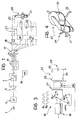
- an electronically-controlled plasma ignition system for internal combustion engines includes control means which include a sensor for sensing the rotation of the drive shaft, consisting for example of a light-emitting diode 2 and a photodiode 3, or a phototransistor, supported on opposite sides of a disc 4 fixed to the drive shaft for rotation therewith.
- control means which include a sensor for sensing the rotation of the drive shaft, consisting for example of a light-emitting diode 2 and a photodiode 3, or a phototransistor, supported on opposite sides of a disc 4 fixed to the drive shaft for rotation therewith.
- the disc 4 has apertures which are distributed angularly in relationship with the firing angle of the engine (in the case of a four-cylinder, in-line engine, for example, there would be two apertures spaced at 180° from each other); these apertures are conveniently positioned in phase with the drive shaft itself.
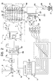
- the output of the rotation sensor 1 is connected electrically to the input of a squaring device 5 with hysteresis, consisting, to advantage, of a differential feedback amplifier with a high response speed.
- one or more monostable devices 6 for example of the TTL or C-MOS type, are connected electrically in cascade and interact with an electronic advance variator 7 which varies the resistance of one of the monostable devices 6 suitably, either gradually or instantaneously, in response to variations in the rate of revolution of the engine.
- the electronic advance variator 7 conveniently comprises a frequency-voltage convertor 8 which receives a signal whose frequency is directly proportional to the rate of revolution of the engine and which is followed by a variable-gain amplifier 9 whose output raises the voltage at the base of a series of operational amplifiers 10, of which there is a greater number, the better the resolution required, connected with the interposition of a first series of resistors 11.
- a selector device 14 for selecting the cylinder in which combustion is to occur which consists, essentially, of a counting unit and a system of logic gates interconnected in such a way that, as shown in Figure 7, a signal is present at each of the outputs 15 of which there are the same number as the number of cylinders of the engine.
- the control means can further conveniently include a start signalling device 16 which, at the end of each operating cycle of the engine, sends a synchronising signal to the selector device 14 to trigger the counting unit at a certain angular position of the drive shaft.
- a start signalling device 16 which, at the end of each operating cycle of the engine, sends a synchronising signal to the selector device 14 to trigger the counting unit at a certain angular position of the drive shaft.
- the outputs 15 of the selector device 14 constitute the outputs of the control means according to the invention and are each conveniently connected to subsequent stages with the interposition of respective photocouplers 17.
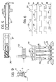
- Each output 15 is connected to a corresponding high-frequency electrical-current generator 18, each of which, to advantage, consists of an oscillator 19 which, as best seen in Figure 3 has two outputs 180° out of phase with each other which drive in counterphase the bases of two power transistors 20 connected in a "push-pull" arrangement.
- the load on the two transistors 20 is the centre-tap primary winding 21 of an ignition transformer 22 with a high transforming ratio which, as shown in Figure 4, has a rectangular-shaped ferrite core and a secondary winding 23 with a very high number of turns in relation to that of the primary winding 21.
- the transformer 22 preferably also has an auxiliary winding 24 connected to two load-monitoring inputs of the respective oscillator 19.
- the ends of the secondary winding 23 of the transformer 22 are connected to two electrical conductors 25 which are brought together in a high-insulation cable 26 (Fig. 5) and which are connected at their opposite ends to a bipolar connector 27; this connector 27 is suitable for attachment to a spark plug 29 which in accordance with the invention, is provided with two conductor rods 30 which are isolated from each other and which can each be connected at one end to the connector 27 and the other ends of which, within the cylinder, form two electrodes 31, both isolated from the engine block and thus from the earth of the circuit.
- the drive shaft rotation sensor 1 produces a pulsed signal which has a wave form indicated by reference numeral 32 in Figure 6, in which the frequency of peaks 33 is directly proportional to the rate of rotation of the engine and in which each peak corresponds to the passage of one of the pistons, during its compression phase, through a predetermined angle with respect to the top-dead-centre point (TDC).
- TDC top-dead-centre point
- the signal 32 passes to the squaring device 5 with hysteresis, which processes the signal, separating it from any undesirable harmonics, and transforming it into the wave form indicated 34; the signal 34, thus manipulated, passes to the monostable devices 6 each of which prolongs the duration of each input pulse 35 by a length of time determined by the combination of the values of the capacitative and resistive components connected in parallel with it.
- first monostable device 6a in which the R-C components are constant and which always displaces the trailing edge of the pulses 35 by the same value, giving rise to a signal 36
- second monostable device 6b in which the value of at least one of its R-C components is varied by the electronic advance variator 7 in accordance with the prevailing operating conditions of the engine so that this monostable device 6b generates a signal 37 whose trailing edge is displaced by a value which changes as the operating conditions of the engine vary.
- the two signals 36 and 37 generated by the two monostable devices 6a and 6b are then recombined, giving rise to a compound signal 38 in which the output pulses 39 still have almost the same duration as the input pulses 35 but which are delayed relative to the latter by an amount which varies with the changes in the operating conditions of the engine, giving rise to the necessary dynamic advance.
- the operation of the electronic advance variator 7 can, in its turn, be summarised, it being observed that the input of the frequency-voltage converter 8 receives the same signal 34 in which the frequency of the pulses 35 clearly increases as the rate of revolution of the engine increases; consequently the voltage output by the converter will increase and, after being brought by the variable gain amplifier 9 to the specific advance requirements of the engine, will be applied to the inputs of the operational amplifiers 10.
- the operational amplifiers pass successively, one after the other, from their passive to their active states (or vice versa as the voltage decreases), consequently opening (or closing) the logic switches 12 controlled by them; obviously, as the state of each logic switch 12 varies, the resistance between the terminals 40 varies and thus the delay time of the relative monostable device 6b varies.
- the compound signal 38 together with the synchronisation signal produced by the start signalling device 16, reaches the selector device 14 which processes it, distributing, in rotation, a signal of the type indicated 41 in Figure 7 to the individual outputs 15 the signal 41 having a control pulse 42 which begins with the leading edge of the pulse at the input concerned with the respective cylinder (i.e. in the case of four cylinders, one pulse in four) and ends, for example at the arrival of the next pulse, then remains constantly at zero through the whole of the remaining period.
- Each output 15 thus produces a signal 41 which carries a control pulse 42 which begins at the appropriate stage of advance before TDC of the compression in the cylinder and is maintained for the whole of a predetermined angle of rotation of the drive shaft, for example for the entire period between two successive firings of the engine (and thus for a rotation of 180° in the case of a four cylinder engine).
- Each output 15 of the selector device 14 pilots an oscillator 19 through the photocouplers 17 which transmit the signal exactly without modification and which carry out the protective function of connecting the digital control stage to the subsequent power stage by optical means, thus keeping the two circuits electrically separated.
- a pilot signal 43 identical to the signal 41 at the respective output 15 of the selector device 14, reaches each oscillator 19 which, for the whole duration of the control pulse 42 produces a very high frequency signal at its outputs; it should be stated, on the other hand, that, for the remaining period during which there is no control pulse, the oscillator 19 is inactive and does not absorb energy.
- the two subsequent power transistors 20 practically double the frequency generated by the respective oscillator 19 and apply an electrical signal to the primary winding 21 of the respective ignition transformer 22 so that, during the whole period of activation of the respective oscillator 19, a corresponding very-high-frequency, high-voltage electrical current is supplied to the secondary winding 23, with the waveform indicated by the reference numeral 46.
- the output 46 of the secondary winding 23 is thus carried by the cable 26 to the plug 29, causing a voltaic arc to be struck between its two electrodes 31, this arc being maintained throughout the period of activation of the respective oscillator 19, that is, with reference to the rotation of the drive shaft, from the angle of advance relating to the prevailing rate of revolution up to a large angle of expansion, giving rise to a continuous plasma of high-speed electrons having a high heating effect which is manifested as an enormous capacity to initiate, and subsequently to encourage, combustion of the mixture introduced.
- the intensity of the signal generated by the oscillator is controlled by means of the auxiliary winding 24 in dependence on the load on the secondary winding 23, in such a way as to maintain a constant output from the secondary winding even when the resistance between the two electrodes 31 varies.
- a first block 53 can be provided which encloses all the components, with the obvious exception of the rotation sensor 1 and the ignition transformers which can conveniently be housed in a second block 54 positioned near to the spark plugs; the first block 53 will be supplied by the electrical system of the vehicle.
- the limiting device 48 comprises a high-voltage diode bridge 49 connected to the secondary winding 23 via R-C circuits 50 with inductors 51 at its opposite vertices; this limiting device 48 fulfils an antiresonance function and, by attenuating the voltage peaks, avoids disturbances being transmitted to the electrical system of the vehicle through the earthed electrode 52 of the plug 47.
- the electronically-controlled plasma ignition system of the invention enables a high-power electrical spark to be maintained in the combustion chamber for the whole of the period dictated by the control means, which is first able to trigger combustion efficiently on a broad front and then encourages the maintenance of a more efficient and complete combustion, with the result that the combustion process is notably optimised.
- the ignition power of the plasma beam between the plug electrodes means that it is fully able to trigger efficient combustion under all running conditions of the engine, even at higher speeds, and also enables large quantities of fuel which are admitted suddenly into the cylinders, for example due to sudden pressure on the accelerator, to be burnt smoothly; an appreciable improvement in the performance of the engine is thus obtained under all conditions, this being particularly apparent even in the case of abrupt accelerations combined with heavy loading of the engine.
- the improved combustion obtained results in more complete utilization of the fuel introduced into the cylinders and thus permits the fuel consumption to be reduced appreciably for the same performance.
- the use of a device according to the invention permits the pollutant emissions from an engine to be reduced appreciably with the practical elimination of unburnt fuel from the exhaust gases and immediate, beneficial results from the point of view of reducing atmospheric pollution; moreover, a further possible improvement in this field could be obtained simply by the suitable calibration of the control means, for example, so as to modify the duration of the arc or by the activation of supplementary arcs between the plug electrodes during the exhaust phase to complete the combustion of any imflammable residues even during expulsion of the gas. And furthermore, in addition to the principal results mentioned above, the more homogeneous and gradual combustion obtained produces reduced pressure waves, with clear reductions in the noise and vibrations produced by the engine.
- All that part of the system which precedes the ignition transformer(s) can, moreover, be supplied at low voltage from the electrical system of the vehicle, the only increase in voltage occurring at the transformer(s) and with very great efficiency due both to the particular structure of the transformer itself and the fact that the increase in voltage is not produced by sudden transitory phenomena but rather by the transformation of a high-frequency alternating current.
- the optical rotation sensor 1 could be replaced by other sensors, for example, of the magnetic type; the electronic advance variator could have a different structure and could possibly consist of electronic components already present in the vehicle, could operate continuously or intermittently for short or long periods and be connected to other monitoring devices to make it sensitive, for example, to the load applied to the engine, to the performance required, etc; the photocouplers 17 could be eliminated or replaced by a similar connection system; and further, oscillators with a single output combined with a transistor and a diode connected in a "fly-back" arrangement could be used as the means for generating the high-frequency electrical current.
Landscapes
- Engineering & Computer Science (AREA)
- Chemical & Material Sciences (AREA)
- Combustion & Propulsion (AREA)
- Mechanical Engineering (AREA)
- General Engineering & Computer Science (AREA)
- Physics & Mathematics (AREA)
- Plasma & Fusion (AREA)
- Ignition Installations For Internal Combustion Engines (AREA)
Claims (14)
- Elektronisch gesteuertes Plasma-Zündsystem für eine Brennkraftmaschine, mit
wenigstens einer Zündkerze (29) für jeden Zylinder der Maschine,
einem Rotationsensor (1) zur Überwachung der Drehung der Antriebswelle der Maschine,
mehreren Zündspulen (22) mit jeweils einer Primärwicklung (21) und einer Sekundärwicklung (23), wobei die Sekundärwicklung (23) jeder Zündspule (22) mit einer zugeordneten Zündkerze (29) verbunden ist,
mehreren Stromgeneratoren (18), von denen jeder mit der Primärwicklung (21) einer zugeordneten Zündspule (22) verbunden ist, und
mit den Sensormitteln (1) verbundenen elektronischen Steuermitteln (5 bis 17) zur Aktivierung der einzelnen Stromgeneratoren (18) in Abhängigkeit von der Verbrennungsphase in dem jeweiligen Zylinder zur Erzeugung eines elektronischen Plasmas zwischen den Elektroden der zugeordneten Zündkerze (29),
dadurch gekennzeichnet,
daß jede der Zündspulen (22) jeweils eine mit der Sekundärwicklung (23) magnetisch gekoppelte Hilfswicklung (24) aufweist zur Lieferung eines Signals, das für die Impedanz zwischen den Elektroden der zugeordneten Zündkerze (29) kennzeichnend ist,
und daß jeder der Stromgeneratoren (18) einen Oszillator (19) aufweist, der mit der Primärwicklung (21) und der Hilfswicklung (24) der zugeordneten Zündspule (22) verbunden ist,
wobei jeder dieser Oszillatoren (19) so ausgebildet ist, daß er an die Primärwicklung (21) der betreffenden Zündspule (22) ein Signal anlegen kann, dessen Intensität in Abhängigkeit von dem von der zugeordneten Hilfswicklung (24) gelieferten Signal variabel ist, so daß in jeder Verbrennungsphase eine im wesentlichen konstante Plasmaströmung zwischen den Elektroden der zugeordneten Zündkerze (29) aufrechterhalten wird. - Zündsystem nach Anspruch 1, dadurch gekennzeichnet, daß der Rotationssensor (1) elektrisch mit einem Rechteckwellen-Signalwandler (5) mit Hysterese verbunden ist, der mit wenigstens einer monostabilen Anordnung (6) verbunden ist, die mit einer Auswahlvorrichtung (14) zur Auswahl des Zylinders verbunden ist, in dem eine Verbrennung abläuft, wobei die Ausgänge dieser Auswahlvorrichtung (14) mit den Stromgeneratoren (18) verbunden sind.
- Zündsystem nach Anspruch 2, dadurch gekennzeichnet, daß der Rechteckwellen-Signalwandler (5) einen Rückkopplungs-Differenzverstärker aufweist.
- Zündsystem nach Anspruch 2, dadurch gekennzeichnet, daß die Auswahlvorrichtung (14) eine Zähleinheit und ein System von logischen Gatterschaltungen aufweist.
- Zündsystem nach Anspruch 2, dadurch gekennzeichnet, daß die Steuermittel (5 bis 17) einen elektronischen Variator (7) zur Änderung des Vorlaufs aufweist, der einen mit wenigstens einer der monostabilen Anordnungen (6) verbundenen Widerstand entsprechend der Drehgeschwindigkeitsänderung der Maschine modifiziert.
- Zündsystem nach Anspruch 5, dadurch gekennzeichnet, daß der elektronische Vorlauf-Variator (7) einen Frequenz/Spannungswandler (8) umfaßt, der mit dem Eingang eines Verstärkers (9) mit veränderbarem Verstärkungsfaktor verbunden ist, dessen Ausgang mit dem Eingang einer Gruppe von Komparatoren (10) mit unterschiedlichen Referenz-Schwellwerten verbunden ist, die den Schaltzustand einer entsprechenden Anzahl von Schaltern (12) steuern, mittels derer der Gesamtwiderstand einer Kette von Widerständen (13) veränderbar ist, die mit einer der monostabilen Anordnungen (6) verbunden sind.
- Zündsystem nach Anspruch 2, dadurch gekennzeichnet, daß die Steuermittel (5 bis 17) eine Startsignalisierungseinrichtung (16) umfassen, die bei Beendigung eines Arbeitszyklus der Maschine jeweils ein Synchronisiersignal an die Auswahlvorrichtung (14) sendet.
- Zündsystem nach einem oder mehreren der Ansprüche 2 bis 7, dadurch gekennzeichnet, daß jeder Ausgang der Auswahlvorrichtung (14) über einen Optokoppler (17) mit dem betreffenden Stromgenerator (18) verbunden ist.
- Zündsystem nach Anspruch 1, dadurch gekennzeichnet, daß die Stromgeneratoren (18) jeweils einen Oszillator (19) aufweisen, der zwei um 180° gegeneinander phasenverschobene Ausgangssignale liefert, mit denen die Basiselektroden eines Paares von Leistungstransistoren (20) gegenphasig ansteuerbar sind, deren Last die Primärwicklung (21) einer Zündspule (22) bildet.
- Zündsystem nach Anspruch 1, dadurch gekennzeichnet, daß jeder Stromgenerator (18) einen Oszillator mit einem einzigen Ausgang aufweist, der mit einem Transistor und einer Diode in Freilaufschaltung verbunden ist.
- Zündsystem nach einem oder mehreren der vorhergehenden Ansprüche, dadurch gekennzeichnet, daß jede Zündspule (22) einen Ferritkern mit im wesentlichen rechteckigem Umfang aufweist, der von der Primärwicklung (21) und der Sekundärwicklung (23) umgeben ist, wobei letztere eine sehr viel größere Windungszahl hat als die Primärwicklung (21).
- Zündsystem nach Anspruch 1, dadurch gekennzeichnet, daß jede Zündkerze (29) zwei elektrisch voneinander isolierte Leiterstäbe (30) aufweist, die mit ihren Enden in dem Zylinder in zwei voneinander isolierten Elektroden (31) münden, zwischen denen das elektronische Plasma erzeugt wird, wobei die Leiterstäbe (30) mit ihren entgegengesetzten Enden mit einem zweipoligen Steckverbinder (27) verbindbar sind, der elektrisch mit den Enden der Sekundärwicklung (23) verbindbar ist.
- Zündsystem nach einem oder mehreren der vorhergehenden Ansprüche, dadurch gekennzeichnet, daß es zwischen jeder Zündspule (22) und der zugeordneten herkömmlichen Zündkerze (47) eine Begrenzereinrichtung (48) zum Ausfiltern hochfrequenter Störungen aufweist, die zu dem Fahrzeug übertragen werden, wenn herkömmliche Zündkerzen (47) verwendet werden.
- Zündsystem nach Anspruch 13, dadurch gekennzeichnet, daß die Begrenzereinrichtung (48) eine Hochspannungs-Diodenbrücke (49) umfaßt, an deren Eingangsanschlüssen RC-Glieder (50) und an deren Ausgangsanschlüssen reaktive Filterelemente (51) angeordnet sind.
Priority Applications (1)
| Application Number | Priority Date | Filing Date | Title |
|---|---|---|---|
| AT87105812T ATE79926T1 (de) | 1986-04-24 | 1987-04-21 | Elektronische plasmazuendsteuerung in einer inneren brennkraftmaschine. |
Applications Claiming Priority (2)
| Application Number | Priority Date | Filing Date | Title |
|---|---|---|---|
| IT8554186 | 1986-04-24 | ||
| IT8685541A IT1204274B (it) | 1986-04-24 | 1986-04-24 | Dispositivo di accensione a controllo elettronico di plasma,per motori a combustione interna |
Publications (3)
| Publication Number | Publication Date |
|---|---|
| EP0242839A2 EP0242839A2 (de) | 1987-10-28 |
| EP0242839A3 EP0242839A3 (en) | 1988-03-30 |
| EP0242839B1 true EP0242839B1 (de) | 1992-08-26 |
Family
ID=11327781
Family Applications (1)
| Application Number | Title | Priority Date | Filing Date |
|---|---|---|---|
| EP87105812A Expired - Lifetime EP0242839B1 (de) | 1986-04-24 | 1987-04-21 | Elektronische Plasmazündsteuerung in einer inneren Brennkraftmaschine |
Country Status (5)
| Country | Link |
|---|---|
| US (1) | US4787360A (de) |
| EP (1) | EP0242839B1 (de) |
| AT (1) | ATE79926T1 (de) |
| DE (1) | DE3781309T2 (de) |
| IT (1) | IT1204274B (de) |
Families Citing this family (17)
| Publication number | Priority date | Publication date | Assignee | Title |
|---|---|---|---|---|
| CA2032488A1 (en) * | 1989-05-12 | 1990-11-13 | Michael A. V. Ward | High efficiency, high output compact cd ignition coil |
| US5429103A (en) * | 1991-09-18 | 1995-07-04 | Enox Technologies, Inc. | High performance ignition system |
| RU2004835C1 (ru) * | 1992-09-17 | 1993-12-15 | Джемал Важевич Чакветадзе | Способ сжигани топливно-воздушной смеси и система зажигани дл его осуществлени |
| EP0634573A1 (de) * | 1993-07-13 | 1995-01-18 | Jury Alexandrovech Papko | Methode und System zur Kontrolle der Zündfunkenfrequenz eines Vielfachfunkenzündsystems |
| US5555862A (en) * | 1994-07-19 | 1996-09-17 | Cummins Engine Company, Inc. | Spark plug including magnetic field producing means for generating a variable length arc |
| US5619959A (en) * | 1994-07-19 | 1997-04-15 | Cummins Engine Company, Inc. | Spark plug including magnetic field producing means for generating a variable length arc |
| US5842456A (en) * | 1995-01-30 | 1998-12-01 | Chrysler Corporation | Programmed multi-firing and duty cycling for a coil-on-plug ignition system with knock detection |
| DE19813993C1 (de) * | 1998-01-30 | 1999-08-19 | Moskhalis | Verfahren zum Betreiben eines Verbrennungsmotors |
| EP1295022B1 (de) | 2000-06-08 | 2007-04-04 | Knite, Inc. | Verbrennungsverbesserungssystem und methode |
| DE10157029A1 (de) | 2001-11-21 | 2003-06-05 | Bosch Gmbh Robert | Hochfrequenzzündung für eine Brennkraftmaschine |
| NL1019448C2 (nl) * | 2001-11-29 | 2003-06-03 | Simon Lucas Goede | Verbrandingsmotor en ontstekingscircuit voor een verbrandingsmotor. |
| DE10243271A1 (de) * | 2002-09-18 | 2003-12-04 | Bosch Gmbh Robert | Vorrichtung zum Zünden eines Luft-Kraftstoff-Gemischs in einem Verbrennungsmotor |
| DE102004039406A1 (de) * | 2004-08-13 | 2006-02-23 | Siemens Ag | Plasma-Zünd-Verfahren und -Vorrichtung zur Zündung von Kraftstoff/Luft-Gemischen in Verbrennungskraftmaschinen |
| AT414319B (de) * | 2004-10-22 | 2007-02-15 | Ge Jenbacher Gmbh & Co Ohg | Zündkerzenstecker |
| FR2919343B1 (fr) * | 2007-07-25 | 2013-08-16 | Renault Sas | Moteur a combustion et procede de commande d'un moteur a combustion. |
| DE102010045044B4 (de) * | 2010-06-04 | 2012-11-29 | Borgwarner Beru Systems Gmbh | Verfahren zum Zünden eines Brennstoff-Luft-Gemisches einer Verbrennungskammer, insbesondere in einem Verbrennungsmotor, durch Erzeugen einer Korona-Entladung |
| DE102013108705B4 (de) * | 2013-08-12 | 2017-04-27 | Borgwarner Ludwigsburg Gmbh | Koronazündsystem und Verfahren zum Steuern einer Koronazündeinrichtung |
Family Cites Families (13)
| Publication number | Priority date | Publication date | Assignee | Title |
|---|---|---|---|---|
| US1225535A (en) * | 1915-04-27 | 1917-05-08 | Richard Varley | Electrical system. |
| US2180704A (en) * | 1936-11-14 | 1939-11-21 | Siemens App Und Maschinen Gmbh | Interference preventing arrangement for internal combustion engines |
| US3202146A (en) * | 1962-04-11 | 1965-08-24 | Gen Motors Corp | Static transistorized ignition system |
| FR2312126A1 (fr) * | 1975-05-21 | 1976-12-17 | Mayer Ferdy | Dispositif antiparasites pour moteur a explosions |
| JPS5821112B2 (ja) * | 1976-07-26 | 1983-04-27 | 株式会社シグマエレクトロニクスプランニング | スパ−クプラグ点火装置 |
| US4206737A (en) * | 1977-07-05 | 1980-06-10 | Gerry Martin E | Modulated ignition system |
| US4359998A (en) * | 1979-11-28 | 1982-11-23 | Topic Eugene F | Ignition system for internal combustion engines |
| EP0034787B1 (de) * | 1980-02-21 | 1985-05-15 | Siemens Aktiengesellschaft | Zündsystem für Brennkraftmaschinen |
| JPS5732069A (en) * | 1980-07-31 | 1982-02-20 | Nissan Motor Co Ltd | Igniter for internal combustion engine |
| JPS5756667A (en) * | 1980-09-18 | 1982-04-05 | Nissan Motor Co Ltd | Plasma igniter |
| US4446842A (en) * | 1981-06-01 | 1984-05-08 | Aisin Seiki Kabushiki Kaisha | Ignition system |
| FR2574119B1 (fr) * | 1984-12-04 | 1987-02-20 | Bendix Electronics Sa | Systeme electronique d'elaboration d'un signal synchrone d'un signal d'allumage de moteur a combustion interne |
| DE3513422C2 (de) * | 1985-04-15 | 1993-10-28 | Beru Werk Ruprecht Gmbh Co A | Zündanlage für Brennkraftmaschinen |
-
1986
- 1986-04-24 IT IT8685541A patent/IT1204274B/it active
-
1987
- 1987-04-21 AT AT87105812T patent/ATE79926T1/de not_active IP Right Cessation
- 1987-04-21 DE DE8787105812T patent/DE3781309T2/de not_active Expired - Fee Related
- 1987-04-21 EP EP87105812A patent/EP0242839B1/de not_active Expired - Lifetime
- 1987-04-23 US US07/041,506 patent/US4787360A/en not_active Expired - Fee Related
Also Published As
| Publication number | Publication date |
|---|---|
| US4787360A (en) | 1988-11-29 |
| ATE79926T1 (de) | 1992-09-15 |
| EP0242839A3 (en) | 1988-03-30 |
| EP0242839A2 (de) | 1987-10-28 |
| DE3781309D1 (de) | 1992-10-01 |
| IT1204274B (it) | 1989-03-01 |
| DE3781309T2 (de) | 1993-03-25 |
| IT8685541A0 (it) | 1986-04-22 |
Similar Documents
| Publication | Publication Date | Title |
|---|---|---|
| EP0242839B1 (de) | Elektronische Plasmazündsteuerung in einer inneren Brennkraftmaschine | |
| US4033316A (en) | Sustained arc ignition system | |
| US5568801A (en) | Plasma arc ignition system | |
| GB2085076A (en) | Plasma ignition system | |
| US4245594A (en) | Ignition device | |
| JP2597126B2 (ja) | 内燃機関の点火火花を発生する方法および装置 | |
| GB2081810A (en) | Plasma ignition system for an internal combustion engine | |
| US3943896A (en) | Electronic control of spark advance and dwell | |
| EP0072477B1 (de) | Zündsystem für einen polyzylindrischen Brennkraftmotor | |
| US3034018A (en) | Transistorized breakerless ignition system | |
| US3408536A (en) | Breakerless oscillator ignition system | |
| US3935844A (en) | Ignition timing control system | |
| US4051828A (en) | Ignition system for use with internal combustion engines | |
| GB2087483A (en) | Extended duration ignition pulse circuits | |
| US4161936A (en) | Audio frequency ionization ignition system | |
| EP0270162B1 (de) | Zündeinheit mit magnetischem Schwungrad für Brennkraftmaschinen mit innerer Verbrennung | |
| US4381757A (en) | Continuous type ignition device for an internal combustion engine | |
| US4414954A (en) | Internal combustion engine ignition system with improvement | |
| US3504231A (en) | Breakerless oscillator ignition system | |
| GB2038943A (en) | Spark Ignition Devices for Internal Combustion Engines | |
| US3502060A (en) | Electronic ignition system | |
| US4909228A (en) | Ignition apparatus | |
| RU2276282C2 (ru) | Система зажигания двигателя внутреннего сгорания | |
| JP3116964B2 (ja) | エンジンの点火装置 | |
| RU2190911C2 (ru) | Система зажигания |
Legal Events
| Date | Code | Title | Description |
|---|---|---|---|
| PUAI | Public reference made under article 153(3) epc to a published international application that has entered the european phase |
Free format text: ORIGINAL CODE: 0009012 |
|
| AK | Designated contracting states |
Kind code of ref document: A2 Designated state(s): AT BE CH DE ES FR GB GR IT LI LU NL SE |
|
| PUAL | Search report despatched |
Free format text: ORIGINAL CODE: 0009013 |
|
| AK | Designated contracting states |
Kind code of ref document: A3 Designated state(s): AT BE CH DE ES FR GB GR IT LI LU NL SE |
|
| 17P | Request for examination filed |
Effective date: 19880916 |
|
| 17Q | First examination report despatched |
Effective date: 19900615 |
|
| RAP3 | Party data changed (applicant data changed or rights of an application transferred) |
Owner name: EL.EN.A. S.R.L. (ELECTRONIC ENGINEERING APPLICATIO |
|
| GRAA | (expected) grant |
Free format text: ORIGINAL CODE: 0009210 |
|
| AK | Designated contracting states |
Kind code of ref document: B1 Designated state(s): AT BE CH DE ES FR GB GR IT LI LU NL SE |
|
| PG25 | Lapsed in a contracting state [announced via postgrant information from national office to epo] |
Ref country code: IT Free format text: LAPSE BECAUSE OF FAILURE TO SUBMIT A TRANSLATION OF THE DESCRIPTION OR TO PAY THE FEE WITHIN THE PRE;WARNING: LAPSES OF ITALIAN PATENTS WITH EFFECTIVE DATE BEFORE 2007 MAY HAVE OCCURRED AT ANY TIME BEFORE 2007. THE CORRECT EFFECTIVE DATE MAY BE DIFFERENT FROM THE ONE RECORDED.SCRIBED TIME-LIMIT Effective date: 19920826 Ref country code: SE Free format text: THE PATENT HAS BEEN ANNULLED BY A DECISION OF A NATIONAL AUTHORITY Effective date: 19920826 Ref country code: GR Free format text: LAPSE BECAUSE OF FAILURE TO SUBMIT A TRANSLATION OF THE DESCRIPTION OR TO PAY THE FEE WITHIN THE PRESCRIBED TIME-LIMIT Effective date: 19920826 Ref country code: AT Effective date: 19920826 Ref country code: LI Effective date: 19920826 Ref country code: CH Effective date: 19920826 |
|
| REF | Corresponds to: |
Ref document number: 79926 Country of ref document: AT Date of ref document: 19920915 Kind code of ref document: T |
|
| REF | Corresponds to: |
Ref document number: 3781309 Country of ref document: DE Date of ref document: 19921001 |
|
| ET | Fr: translation filed | ||
| REG | Reference to a national code |
Ref country code: CH Ref legal event code: PL |
|
| PG25 | Lapsed in a contracting state [announced via postgrant information from national office to epo] |
Ref country code: ES Free format text: LAPSE BECAUSE OF FAILURE TO SUBMIT A TRANSLATION OF THE DESCRIPTION OR TO PAY THE FEE WITHIN THE PRESCRIBED TIME-LIMIT Effective date: 19921207 |
|
| PGFP | Annual fee paid to national office [announced via postgrant information from national office to epo] |
Ref country code: NL Payment date: 19930430 Year of fee payment: 7 |
|
| PLBE | No opposition filed within time limit |
Free format text: ORIGINAL CODE: 0009261 |
|
| STAA | Information on the status of an ep patent application or granted ep patent |
Free format text: STATUS: NO OPPOSITION FILED WITHIN TIME LIMIT |
|
| 26N | No opposition filed | ||
| PGFP | Annual fee paid to national office [announced via postgrant information from national office to epo] |
Ref country code: BE Payment date: 19931027 Year of fee payment: 7 |
|
| PGFP | Annual fee paid to national office [announced via postgrant information from national office to epo] |
Ref country code: LU Payment date: 19931101 Year of fee payment: 7 |
|
| EPTA | Lu: last paid annual fee | ||
| PG25 | Lapsed in a contracting state [announced via postgrant information from national office to epo] |
Ref country code: LU Free format text: LAPSE BECAUSE OF NON-PAYMENT OF DUE FEES Effective date: 19940421 |
|
| PG25 | Lapsed in a contracting state [announced via postgrant information from national office to epo] |
Ref country code: BE Effective date: 19940430 |
|
| PGFP | Annual fee paid to national office [announced via postgrant information from national office to epo] |
Ref country code: DE Payment date: 19941017 Year of fee payment: 8 |
|
| PGFP | Annual fee paid to national office [announced via postgrant information from national office to epo] |
Ref country code: GB Payment date: 19941018 Year of fee payment: 8 |
|
| PGFP | Annual fee paid to national office [announced via postgrant information from national office to epo] |
Ref country code: FR Payment date: 19941028 Year of fee payment: 8 |
|
| BERE | Be: lapsed |
Owner name: ELECTRONIC ENGINEERING APPLICATION ELENA S.R.L. Effective date: 19940430 |
|
| PG25 | Lapsed in a contracting state [announced via postgrant information from national office to epo] |
Ref country code: NL Effective date: 19941101 |
|
| NLV4 | Nl: lapsed or anulled due to non-payment of the annual fee | ||
| PG25 | Lapsed in a contracting state [announced via postgrant information from national office to epo] |
Ref country code: GB Effective date: 19950421 |
|
| GBPC | Gb: european patent ceased through non-payment of renewal fee |
Effective date: 19950421 |
|
| PG25 | Lapsed in a contracting state [announced via postgrant information from national office to epo] |
Ref country code: FR Effective date: 19951229 |
|
| PG25 | Lapsed in a contracting state [announced via postgrant information from national office to epo] |
Ref country code: DE Effective date: 19960103 |
|
| REG | Reference to a national code |
Ref country code: FR Ref legal event code: ST |