EP0242739A2 - Ein-Buchstaben Alphabet - Google Patents
Ein-Buchstaben Alphabet Download PDFInfo
- Publication number
- EP0242739A2 EP0242739A2 EP87105340A EP87105340A EP0242739A2 EP 0242739 A2 EP0242739 A2 EP 0242739A2 EP 87105340 A EP87105340 A EP 87105340A EP 87105340 A EP87105340 A EP 87105340A EP 0242739 A2 EP0242739 A2 EP 0242739A2
- Authority
- EP
- European Patent Office
- Prior art keywords
- lines
- along
- symbols
- displayed
- symbol
- Prior art date
- Legal status (The legal status is an assumption and is not a legal conclusion. Google has not performed a legal analysis and makes no representation as to the accuracy of the status listed.)
- Granted
Links
Images


Classifications
-
- G—PHYSICS
- G09—EDUCATION; CRYPTOGRAPHY; DISPLAY; ADVERTISING; SEALS
- G09F—DISPLAYING; ADVERTISING; SIGNS; LABELS OR NAME-PLATES; SEALS
- G09F9/00—Indicating arrangements for variable information in which the information is built-up on a support by selection or combination of individual elements
- G09F9/30—Indicating arrangements for variable information in which the information is built-up on a support by selection or combination of individual elements in which the desired character or characters are formed by combining individual elements
- G09F9/302—Indicating arrangements for variable information in which the information is built-up on a support by selection or combination of individual elements in which the desired character or characters are formed by combining individual elements characterised by the form or geometrical disposition of the individual elements
-
- B—PERFORMING OPERATIONS; TRANSPORTING
- B43—WRITING OR DRAWING IMPLEMENTS; BUREAU ACCESSORIES
- B43L—ARTICLES FOR WRITING OR DRAWING UPON; WRITING OR DRAWING AIDS; ACCESSORIES FOR WRITING OR DRAWING
- B43L13/00—Drawing instruments, or writing or drawing appliances or accessories not otherwise provided for
- B43L13/20—Curve rulers or templets
- B43L13/201—Stencils for drawing figures, objects
- B43L13/208—Stencils for drawing figures, objects letters, numbers, symbols
-
- G—PHYSICS
- G09—EDUCATION; CRYPTOGRAPHY; DISPLAY; ADVERTISING; SEALS
- G09D—RAILWAY OR LIKE TIME OR FARE TABLES; PERPETUAL CALENDARS
- G09D3/00—Perpetual calendars
- G09D3/04—Perpetual calendars wherein members bearing the indicia are movably mounted in the calendar
- G09D3/10—Perpetual calendars wherein members bearing the indicia are movably mounted in the calendar with members in band form
-
- G—PHYSICS
- G09—EDUCATION; CRYPTOGRAPHY; DISPLAY; ADVERTISING; SEALS
- G09F—DISPLAYING; ADVERTISING; SIGNS; LABELS OR NAME-PLATES; SEALS
- G09F7/00—Signs, name or number plates, letters, numerals, or symbols; Panels or boards
- G09F7/02—Signs, plates, panels or boards using readily-detachable elements bearing or forming symbols
- G09F7/14—Constructional features of the symbol bearing or forming elements
Definitions
- the present invention deals with a common symbol for writing, signs and displays, etc., used to represent a group of symbols where each symbol of the said group be represented on the said common symbol.
- the present invention deals with a common symbol representing a group of symbols where each of the said symbols could be represented individually on the said common symbol by using: colored ink, fillers, ties, beaming lights, heating, magnetic or light elements, along the lines of the symbol to be displayed and in other cases by using magnetized blocks along the tracks of the symbol to be displayed, and moreover by using unilevel and multilevel, various size common symbols made of individual bars or elements grouped in different combinations to type or print the required symbol, letter or figure of a selected size with one single command.
- the present invention deals with guided writing and interchangeable signs, displays and illustrations, using a common symbol representing a group of symbols, electrical, musical, alpha-numeric or the like, where each individual symbol of the group could be represented and displayed separately on the said common symbol, generally as shown on the drawings and subsequently described hereinafter:
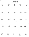
- Fig 1 shows 9 fixed holding means distributed at 9 points forming 3 parellel lines, considered as the 3 horizontal lines; 1.2.3, 4.5.6, 7.8.9, or 3 vertical lines; 1.4.7, 2.5.8, 3.6.9.
- the tie connecting the different holders should be of a visible color in contrast with the surface behind it.
- This system could be applicable for mini signs, illustrations and displays, as well as for very large ones that could not be realized with the prior art.
- the mini displays could be distinguished visually as well as with a touching process.
- the central holding mean No. 5 is split into two holding means, 5A and 5B to allow better connections to ties coming from different directions.
- Fig. 2 is a simplification of fig. 1, it shows only 6 holding means out of the 9 original holding means shown in fig. 1, namely; 1.3, 4.6, 7.9.
- the 6 holding means are equally distributed along 2 vertical lines; 1.4.7 and 3.6.9.
- the simplified fig. 2 is a common symbol generally considered for the numbers 1 to 9.
- anyone of the numbers could be represented individually by means of a flexible tie joining the required number of holding means in a required pattern to show the required number.
- Fig. 3 shows the same 9 basic holding means shown in fig. 1 plus 14 additional secondary holding means distributed around the 6 outer holding means which are: 1R. 1D.,3L. 3D., 4U. 4R. 4D., 6U. 6L. 6D., 7U. 7R., 9U. 9L.
- the 14 additional holding means allow the representation of the symbols in the same way as in fig. 1 but with more contour details than would be possible with the 9 basic holding means shown in fig. 1.
- Fig. 4 shows the same holding means shown in fig. 3, plus 6 additional holding means, namely: 2L. 2R. 2D., and 8U. 8L. 8R.
- the 6 additional holding means allow the additional representation of the lower case symbols of the alpha-numeric.
- Fig. 5 shows basically the same 9 holding means shown in fig. 1.
- Fig. 5 shows additional holding means superimposed within the 9 original holding means shown in fig. 1.
- the additional holding means at points (1.2), (4.5), (7.8), combined with points 1.2, 4.5, 7.8, create at the left half of fig. 5 another fig. of 9 holding means, similar to fig. 1, which serves by itself as a common symbol for a group of alpha-numeric characters, the same as is possible on fig. 1 itself.
- the holding means are made to space the different ties horizontally and vertically, so that they would not obscure each other. This is accomplished by having multi-level holders with wide pulley like circles at the bottom and smaller ones above (see fig. 18a).
- Fig. 6 is the same as fig. 1 to 4, with the difference that the holding means, shown in fig. 1 to 4, in a horseshoe shape, or the like, are reduced to simple curvilinear C shape cut lines raised over the surface.
- the pages written by means of flexible ties could be used for printing by mounting raised flexible ties soaked with dry stamp carbon or the like and using the assembly as a stamp itself to print it on another surface.
- Fig 7 shows 9 or more holding means distributed in a similar way to those in fig. 1 to 4 and connected with ties, provided with a succession of lights, joining the following holding means: 1-2-3, 4-5-6, 7-8-9, 1-4-7, 2-5-8, 3-6-9, 1-5-9, 3-5-7, 1-8, 2-7, 2-9, 3-8 or the like.
- Each set of sections of the lines joining the holding means are connected to an electric source in different combinations in a way that by switching on the current to one combination, any symbol of the alpha-numeric could be displayed separately by lighting the set of lines representing it.
- the arrangement shown in fig. 7 could be used for small and large displays, from one foot symbols, or less, to one hundred foot symbols or more.
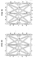
- Fig. 8 shows parallel lines representing continuous grooves, channels or the like, joining the locations of the original 9 holding means shown in fig. 1.
- the continuous grooves are distributed in the following pattern: A - 3 horizontal parellel grooves namely: 1-2-3, 4-5-6, 7-8-9.
- B - Vertical parellel grooves namely: 1-4-7, 2-5-8, 3-6-9, perpendicular to the first 3 horizontal grooves.
- C - 2 cross diagonal grooves namely: 1-5-9, 3-5-7.
- E- 2 diagonals in the right half of the picture namely: 2-9, 3-8.
- any symbol of the alpha numeric could be displayed on Fig. 8 in one of the following manners: A- By colouring the groove along the lines of the required symbol with a colour in contrast with the remaining colour of the surface containing Fig. 8.
- the advantage of this method is that it offers a guided writing resulting in a neat presentation of the required symbols which could be best used in headlines, labels, on addresses which fact makes it easier to the sensing devices to distinguish the said symbols.
- the patterns shown on Figs. 8 to 14 could be either embossed, engraved, moulded, cast or the like on paper, plastic, metal, wood, etc., and they could be used for displaying symbols, for writing, for labels, addresses, letterheads, for name plates, for price tags, large signs on buildings, etc.
- Fig. 9 shows a simplified picture of Fig. 8 reducing it simply to 2 rectangles standing up over each other resulting in a continuous groove in the following pattern: A- 3 horizontal parallel grooves; 1-3, 4-6, 7-9. B- 2 vertical grooves; 1-4-7, 3-6-9, perpendicular to, and bordering the 3 horizontal grooves forming together a straight Figure Eight.
- the resulting figure 9 represents a common symbol for the ten arabic numbers where any of the numbers could be displayed separately on it.
- Fig. 10 shows the basic continuous grooves shown on Fig. 8 with additional concave, curvilinear grooves on the corners 1, 3, 7, 9 like 1R-1D, and double opposite grooves on the corners 4 and 6, like the grooves 4U-4R, etc.
- Fig. 10 allows the representation of the alpha numeric symbols with more distinguishable contour lines than it would be possible with Fig. 8.
- Fig. 11 shows the same continuous grooves shown in Fig. 10 with additional similar opposite curvilinear grooves on the corners 2 and 8, like 2L-2D, 2R-2D, etc.
- Fig. 11 allows the additional representation of the lower case alpha numeric symbols which was not possible on Fig. 10.
- Fig. 12 is the same as Fig. 11 with the difference that the curvilinear grooves located on the corners are changed into straight line grooves.
- the straight line grooves like 1R-1D, allow the use of straight rotatable cylinders in the grooves, which was not possible with the curvilinear grooves on Fig. 11.
- Fig. 13 is basically the same as Fig. 8 with mini figures, like No. 8, superimposed inside the major figure using the same principle described in Fig. 5.
- Fig. 14 is basically the same as described for figures 8 to 13 except that the lines in Fig. 14 represent a continuous raised track in a similar way to a rail track, and with mini wagon-like units rolling along said track, and by positioning said units along the different sections of the track, any of the required symbols could be displayed.
- the track consists of a simple metallic track with mini-wagon-like rollers moving along said track with either the track itself or the rollers being magnetized to keep them holding to each other.
- Fig. 15 shows an assembly of a handle, like No. 1, with a spool, like No. 5, a tie attached to a self-threading needle used altogether as a pen to spread the tie No. 6 in between the different holding means, shown on Fig. 1 to 6.
- the No. 2 is inserted in the horseshoe-shaped holding means to allow the tie No. 6 to hook behind the core of the horseshoe shape and by spreading the tie in between different sets of holding means, any symbol represented on the common symbol could be displayed on any of the Figs. 1 to 5.
- the tie No. 6 is usually coloured in contrast with the surface on which it is spread. This fact allows the symbols displayed to be distinguished visually, as well as with a touching process.
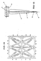
- Fig. 16 shows a mini common symbol of a group of symbols represented with a continuous groove on a solid ruler. This arrangement is used as a guide for a scriber instrument to mark any of the required symbols with a coloured ink generally by means of a 3 pin guided scriber. The first pin passing through the model groove, the second pin is guided by a separate straight groove while the third pin is marking on an outside surface the same line followed by the first pin in the model.
- Fig. 17 shows a set of templates, of different sizes, of the types shown in Fig. 17A mounted on a ruler provided with rollers, like No. 3, at both ends to allow it to roll up and down and with suction cups, like No. 5 to allow it to be fixed on the surface supporting it.
- said ruler is provided with sliding track, like No. 2, to allow the templates, like No. 1, to be moved left and right on the supporting surface.
- Fig. 17A (referred to hereinafter as the blind alphabet template) is basically the same as Figs. 8 to 13 with the difference that the groove is cut through leaving the parts separating the grooves detached from each other, except for certain spots like Nos. 10, 11, 12, etc. to keep the parts separating the grooves holding together with the same spacing all through.
- This arrangement results in a moulding template on which any of the symbols represented by the common symbol could be reproduced on this moulding template.
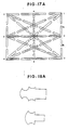
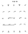
- Fig. 18 shows a similar pattern to that described in Fig. 5 used as a permanent blind alphabet calendar in the following manner:
- Fig. 18A shows the dowels, or holders, used as holding means in the permanent calendar shown on Fig. 18.
- Fig. 19 shows a complete permanent blind alphabet calendar consisting of a fixed row of 5 consecutive weeks plus 2 week days, like No. 1, with exact divisions dividing the 37 week days.
- the top row, No. 1 is followed by 12 separate rows representing 12 months of the year divided with the same divisions used to divide the week days in No. 1.
- Each of the 12 separate rows represent 1 month with the exact number of days of that month printed, or engraved, on it.
- Each row, representing 1 month, is set in its right place in the consecutive order as it occurs in the year.
- the first division of the January row for example, is slided under the first week to correspond with the division of the week day on which January begins, and the following months are set next in the same way.
- the result is a permanent calendar showing the whole days of the year with each month in its right place with regard to the week days.
- Each year, the 12 rows of months are reset in the same way as described above.
- a T-shaped solid piece, or the like, similar to No. 3, is inserted in between the rows under the row of the present month and under the present week to underline the current week.
- a cursor (like No. 8, Fig. 20) sliding over the tip row, No. 1, and extending down to the last of the 12 month rows to indicate the present day at the intersection of the cursor with the month row indicator, No. 3 (Fig. 19).
- Fig. 20 shows a typical chassis on which a permanent calendar could be installed.
- Said chassis consists of a contour frame like 1, 2, 3, 4 with braces, like No. 5, and with hooking means, like No. 9.
- the 12 rows are positioned below the band No. 1 with a cursor, like No. 8, extended from the band, No. 1, over the 12 month rows stacked below.
- Figure 21 has basically the same pattern as figure 8 to 13, except that it uses mobile solid bars, inking elements, lighting, burning, magnetic elements or the like, in between the locations of the holding means.
- Said solid bars or elements are made in separate sections that are connected separately in various combinations to different command centers, and by activating one or more of these command centers, the corresponding set of bars or elements are activated to print, light, burn, display or induce the required symbol or letter.
- a dual superimposed reversed variable size sets of common symbols like Nos. 1, 2, 3, 4, 5, 6, similar to that described in Paragraph 7-21-1 are used, with transversal pins like No. 7, separating the said bars or elements, and in certain cases, communicating the action in between them to print or produce different size symbols on different sheets like Nos. 8, 9, 10 at different levels in between the pairs of the superimposed common symbols.
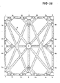
- Fig. 23 shows a set of superimposed common symbols similar to those shown in Fig. 5 and described in Chapter 7-5, with the difference that Fig. 23 shows a frame or mobile holding means consisting of 5 horizontal equidistant bars like No. 6 and another 5 superimposed equidistant cross bars like No. 5 perpendicular to the first ones, creating at their intersections 25 mobile free holding points.
- the horizontal bars are supported at their opposite ends by elastic ties, like No. 9, 10 and the vertical bars are equally supported at their opposite ends by similar elastic ties like No. 7, 8.
- the elastic ties No. 7, 8, 9, 10 are rolled individually around pulleys like No. 11 and converge all together to a common point under a single command.
- any symbol, letter or figure displayed by means of colored elastic ties, interwoven in between the holding means created at the bar crossing, stretches into a larger symbol when the crossing points get apart and shrinks into a smaller symbol or letter when the crossing points get closer.
- Fig. 24 shows an alpha-numeric common symbol with flashing light sources, like No. 1 to 9, located at the intersections of the main lines of the common symbol and beaming along the lines of the said common symbol over strips, like No. 10, covered with mini-reflectors to accentuate the light lines displaying the required letters on the common symbol.
- reflectors are used in place of the light sources, which reflectors reflect the lights directed to them from an adjacent light source and redirect said lights to another strip along the lines of the common symbol.
- Fig. 25 shows an alpha-numeric common symbol similar to that shown on Fig. 24 with additional light sources, like No. 1R to 9L, located at intermediate points in between the main light sources, 1 to 9, to allow the display of capital and non-capital alphanumeric characters and with more details than it would be possible with the light sources on Fig. 24.
- additional light sources like No. 1R to 9L, located at intermediate points in between the main light sources, 1 to 9, to allow the display of capital and non-capital alphanumeric characters and with more details than it would be possible with the light sources on Fig. 24.
- Fig. 26 shows basically the same picture shown on Fig. 24, but with double light sources at the main points 1 to 9 and with additional similar light sources, like No. 1.2, 4.5, 7.8, forming, with the light sources 1, 2, 4, 5, 7, 8, a superimposed common symbol at the left half of the original symbol marked from 1 to 9.
- the light sources at the main points 1 to 9 are made double.
- said light sources are passed through different coloured media to produce different coloured beams, projecting different coloured lines along the lines of the common symbols.
- Said coloured lines are separated with opaque plates, like No. 11, to differentiate the different, displayed superimposed symbols where each one of which is displayed in a different colour at the same time.
- This procedure allows the display of different superimposed symbols, at the same time, identified by their different colours.
- This type of display could be programmed to produce a continuous chain of messages using series of common symbols arranged in lines where different words and sentences could be flashed on the same common symbols continuously one after the other.
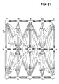
- Fig. 27 shows the same picture shown on Fig. 26 with the difference that the lights are beaming through transparent tubes along the lines of the common symbol.
- the projecting lights pass through coloured media before passing through clear transparent tubes to produce inside said tubes coloured light beams that could be, for example, blue lights, flashing from left to right or red light beams flashing from right ot left, and in other cases, white light beams could be flashing through coloured, transparent tubes producing the same colour display from either direction.
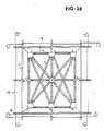
- Fig. 28 shows a combination picture of Fig. 24 superimposed over the grid shown on Fig. 23.
- the light sources No. 1 to 9 are connected to the intersection of the grid of bars No. 11, 12 and in turn said bars are held by elastic ties like No. 13, 14 that are rolled around conversion points, or pulleys, like No. 15, and continuing towards a common point where they could be pulled in or released with one simple command so pulling the grid or bars, No. 11, 12, far apart, pulling with them the light sources at No. 1 to 9, far apart to produce larger displayed symbols, or vice versa.
- Fig. 29 shows similar light sources positioned as those on Fig. 24 with the difference that these light sources on Fig. 29 are beaming through the space along the tracks of the common symbol without the backing strips shown on Fig. 24.
- said lights give vibrating intermittent flashes to accentuate the display of the required symbols.
- This method could be used for space display, for fire-work display, etc.
- central lights are installed at the center of the common symbols, described in Fig. 24 or 29, beaming their lights to reflectors located on the periphery of the common symbol which reflectors redirect said lights along the lines of the characters to be displayed.
- a reduced number of rotative central lights could be used and programmed to rotate towards selected reflectors to display the required letter or figure.
Landscapes
- Physics & Mathematics (AREA)
- General Physics & Mathematics (AREA)
- Engineering & Computer Science (AREA)
- Theoretical Computer Science (AREA)
- Displays For Variable Information Using Movable Means (AREA)
- Illuminated Signs And Luminous Advertising (AREA)
Applications Claiming Priority (4)
| Application Number | Priority Date | Filing Date | Title |
|---|---|---|---|
| CA000507178A CA1253337A (en) | 1986-04-21 | 1986-04-21 | One letter alphabet (ola) |
| CA507178 | 1986-04-21 | ||
| CA521183 | 1986-10-23 | ||
| CA000521183A CA1233447A (en) | 1986-10-23 | 1986-10-23 | Perpetual blind calendar (pbc) |
Publications (3)
| Publication Number | Publication Date |
|---|---|
| EP0242739A2 true EP0242739A2 (de) | 1987-10-28 |
| EP0242739A3 EP0242739A3 (en) | 1989-02-15 |
| EP0242739B1 EP0242739B1 (de) | 1994-04-06 |
Family
ID=25670966
Family Applications (1)
| Application Number | Title | Priority Date | Filing Date |
|---|---|---|---|
| EP87105340A Expired - Lifetime EP0242739B1 (de) | 1986-04-21 | 1987-04-10 | Ein-Buchstaben Alphabet |
Country Status (7)
| Country | Link |
|---|---|
| US (1) | US4838792A (de) |
| EP (1) | EP0242739B1 (de) |
| CN (1) | CN87102909A (de) |
| AU (2) | AU606862B2 (de) |
| BR (1) | BR8701883A (de) |
| DE (1) | DE3789520D1 (de) |
| IN (1) | IN168322B (de) |
Cited By (2)
| Publication number | Priority date | Publication date | Assignee | Title |
|---|---|---|---|---|
| EP0338294A3 (de) * | 1988-04-20 | 1992-01-02 | Ralph Haber Hoyeck | Dauerkalender |
| WO2005073619A1 (en) | 2004-01-05 | 2005-08-11 | Koninklijke Philips Electronics N.V. | Lighting device |
Families Citing this family (10)
| Publication number | Priority date | Publication date | Assignee | Title |
|---|---|---|---|---|
| US5203704A (en) * | 1990-12-21 | 1993-04-20 | Mccloud Seth R | Method of communication using pointing vector gestures and mnemonic devices to assist in learning point vector gestures |
| US5707081A (en) * | 1994-08-26 | 1998-01-13 | Luna; Roberto F. | Alphanumeric quick symbol guide |
| US5661284A (en) * | 1995-03-13 | 1997-08-26 | Albert J. Freeman | Commercial transaction system |
| US6048207A (en) * | 1999-04-22 | 2000-04-11 | Goldin; Fima | Carrier for writing numerical symbols |
| US6544038B2 (en) * | 2001-02-16 | 2003-04-08 | Snowman Natural Learning, Llc | Systems and methods for printing characters using a template |
| GB2440922B (en) * | 2006-07-27 | 2008-10-01 | Benjamin Holmes Peter Shine | Improvements in craft kits |
| US20100264591A1 (en) * | 2009-04-17 | 2010-10-21 | Phillip Lacoi Hutchison | Napkin with printed image promoting interactivity |
| USD643840S1 (en) * | 2010-06-14 | 2011-08-23 | Tin Thanh Nguyen | Trace-to-type character input template |
| US10071592B2 (en) * | 2015-02-24 | 2018-09-11 | Spencer L Brinkerhoff, III | Drawing apparatus and method of use |
| CN116935738A (zh) * | 2023-08-17 | 2023-10-24 | 上海外高桥造船有限公司 | 一种船舶用的字体标记结构及船舶 |
Family Cites Families (23)
| Publication number | Priority date | Publication date | Assignee | Title |
|---|---|---|---|---|
| US1688266A (en) * | 1925-08-17 | 1928-10-16 | Bradford D Coffey | Electrical compound letter |
| DE459685C (de) * | 1926-10-12 | 1928-05-09 | Max Haase Dipl Ing | Vorrichtung zur Vorfuehrung elektrischer Lichtreklamen durch Lampen, welche auf Draehten oder Baendern eines Netzes befestigt sind |
| DE546200C (de) * | 1930-12-07 | 1932-03-10 | Carl Heinz Wittmack | Vorrichtung zur Erleichterung des freihaendigen Zeichnens von Blockschriften |
| FR793864A (fr) * | 1935-08-17 | 1936-02-03 | Perfectionnements apportés aux dispositifs pour la reconstitution, par assemblage de pièces élémentaires, de modèles, notamment de signes d'écriture | |
| DE841262C (de) * | 1950-05-13 | 1952-06-13 | Willi Plaetke | Vorrichtung zum Befestigen von insbesondere Werbematerial |
| GB694042A (en) * | 1950-06-15 | 1953-07-15 | Edgard Vincent Vassallo | An educational game appliance |
| FR1113046A (fr) * | 1954-11-16 | 1956-03-22 | Nouveau dispositif pour publicité lumineuse | |
| FR1303639A (fr) * | 1961-08-04 | 1962-09-14 | Dispositif d'affichage | |
| US3733468A (en) * | 1970-03-18 | 1973-05-15 | United States Banknote Corp | Two track embossing product |
| US3731402A (en) * | 1971-03-08 | 1973-05-08 | G Paul | Educational device |
| CA957498A (en) * | 1972-09-26 | 1974-11-12 | Frances Y. Blunsdon | Method of making displays from kits |
| GB1438537A (en) * | 1973-04-10 | 1976-06-09 | Charman P | Thread or the like designs drawings pictures patterns and creation |
| US3964197A (en) * | 1974-06-24 | 1976-06-22 | Tucker Robert F | Versatile outdoor sign |
| JPS5210098A (en) * | 1975-07-07 | 1977-01-26 | Matsushita Electronics Corp | Optical digital indicator |
| US4012010A (en) * | 1975-12-02 | 1977-03-15 | Friedman Robert W | Thread dispenser |
| CH616522A5 (en) * | 1976-09-23 | 1980-03-31 | Berney Sa Jean Claude | Set of display matrices |
| FR2401680A1 (fr) * | 1977-08-29 | 1979-03-30 | Kuentz Henry | Plaque a tetons permettant de faire des dessins a l'aide d'elastiques en cercle ferme |
| US4257084A (en) * | 1979-02-21 | 1981-03-17 | Reynolds Christopher H | Display device |
| IT1126094B (it) * | 1979-12-11 | 1986-05-14 | Carlo Tamburini | Dispositivo per composizione e visualizzazione di numeri che possono essere formati e cancellati a pia cere manualmente e rapidamente |
| DE3132968A1 (de) * | 1981-08-20 | 1983-04-28 | Siemens AG, 1000 Berlin und 8000 München | Grossanzeigevorrichtung |
| BE895834A (fr) * | 1982-08-19 | 1983-05-30 | Dart Ind Inc | Etiquettes adhesives |
| DE3329310C2 (de) * | 1983-08-13 | 1987-04-16 | Friedrich Merk-Telefonbau GmbH, 8000 München | Sieben-Segment-Anzeigevorrichtung |
| BE898588A (fr) * | 1983-12-29 | 1984-04-16 | Mouraux Rene | Procede et dispositif d'affichage. |
-
1987
- 1987-04-07 AU AU71311/87A patent/AU606862B2/en not_active Ceased
- 1987-04-08 US US07/035,885 patent/US4838792A/en not_active Expired - Fee Related
- 1987-04-10 DE DE87105340T patent/DE3789520D1/de not_active Expired - Lifetime
- 1987-04-10 EP EP87105340A patent/EP0242739B1/de not_active Expired - Lifetime
- 1987-04-18 CN CN87102909A patent/CN87102909A/zh active Pending
- 1987-04-20 IN IN308/CAL/87A patent/IN168322B/en unknown
- 1987-04-21 BR BR8701883A patent/BR8701883A/pt unknown
- 1987-07-07 AU AU75375/87A patent/AU7537587A/en not_active Abandoned
Cited By (2)
| Publication number | Priority date | Publication date | Assignee | Title |
|---|---|---|---|---|
| EP0338294A3 (de) * | 1988-04-20 | 1992-01-02 | Ralph Haber Hoyeck | Dauerkalender |
| WO2005073619A1 (en) | 2004-01-05 | 2005-08-11 | Koninklijke Philips Electronics N.V. | Lighting device |
Also Published As
| Publication number | Publication date |
|---|---|
| IN168322B (de) | 1991-03-16 |
| US4838792A (en) | 1989-06-13 |
| BR8701883A (pt) | 1988-02-02 |
| CN87102909A (zh) | 1987-11-25 |
| DE3789520D1 (de) | 1994-05-11 |
| EP0242739B1 (de) | 1994-04-06 |
| AU7131187A (en) | 1987-10-22 |
| AU606862B2 (en) | 1991-02-21 |
| AU7537587A (en) | 1987-11-05 |
| EP0242739A3 (en) | 1989-02-15 |
Similar Documents
| Publication | Publication Date | Title |
|---|---|---|
| US4838792A (en) | One letter alphabet (OLA) | |
| US6142783A (en) | Handwriting template system | |
| US6237240B1 (en) | Template for creating a layered pattern | |
| US4125658A (en) | Apparatus for use in drawing or marking graphic characters on a surface | |
| US3731402A (en) | Educational device | |
| EP0311874A1 (de) | Modellkopf zur Anwendung im Kosmetikunterricht | |
| US20060059734A1 (en) | Graphic organizers | |
| EA000065B1 (ru) | Способ печати | |
| US3403460A (en) | Mathematical educational apparatus using blocks | |
| CA1253337A (en) | One letter alphabet (ola) | |
| US3529372A (en) | Compartmented article and method of making the same | |
| US3479752A (en) | Publication layout guide | |
| US5096422A (en) | Handicraft guide | |
| US3625149A (en) | Variable design printing means | |
| US4731149A (en) | Apparatus for use in spacing letters | |
| CA1233447A (en) | Perpetual blind calendar (pbc) | |
| US2229757A (en) | Stencil | |
| US2228331A (en) | Examination conducting device | |
| US2079468A (en) | Luminous device and method of and apparatus for making the same | |
| DE2246603A1 (de) | Matrizenstreifen fuer fotodruckmaschinen | |
| EP0850469A1 (de) | Farbkode-markierung von gegenständen | |
| GB2161305A (en) | Manufacture of sign plates | |
| US4533329A (en) | Educational device for teaching the proper placement of information | |
| US5954509A (en) | Educational device | |
| CN213366035U (zh) | 一种可更换式标牌装置 |
Legal Events
| Date | Code | Title | Description |
|---|---|---|---|
| PUAI | Public reference made under article 153(3) epc to a published international application that has entered the european phase |
Free format text: ORIGINAL CODE: 0009012 |
|
| AK | Designated contracting states |
Kind code of ref document: A2 Designated state(s): DE ES FR GB GR IT NL SE |
|
| RHK1 | Main classification (correction) |
Ipc: G09F 7/08 |
|
| PUAL | Search report despatched |
Free format text: ORIGINAL CODE: 0009013 |
|
| AK | Designated contracting states |
Kind code of ref document: A3 Designated state(s): DE ES FR GB GR IT NL SE |
|
| 17P | Request for examination filed |
Effective date: 19890724 |
|
| 17Q | First examination report despatched |
Effective date: 19901031 |
|
| RAP1 | Party data changed (applicant data changed or rights of an application transferred) |
Owner name: KARRASCH, GISELA |
|
| GRAA | (expected) grant |
Free format text: ORIGINAL CODE: 0009210 |
|
| RAP1 | Party data changed (applicant data changed or rights of an application transferred) |
Owner name: HOYECK, RALPH HABER |
|
| AK | Designated contracting states |
Kind code of ref document: B1 Designated state(s): DE ES FR GB GR IT NL SE |
|
| PG25 | Lapsed in a contracting state [announced via postgrant information from national office to epo] |
Ref country code: IT Free format text: LAPSE BECAUSE OF FAILURE TO SUBMIT A TRANSLATION OF THE DESCRIPTION OR TO PAY THE FEE WITHIN THE PRE;WARNING: LAPSES OF ITALIAN PATENTS WITH EFFECTIVE DATE BEFORE 2007 MAY HAVE OCCURRED AT ANY TIME BEFORE 2007. THE CORRECT EFFECTIVE DATE MAY BE DIFFERENT FROM THE ONE RECORDED.SCRIBED TIME-LIMIT Effective date: 19940406 Ref country code: NL Effective date: 19940406 Ref country code: SE Free format text: THE PATENT HAS BEEN ANNULLED BY A DECISION OF A NATIONAL AUTHORITY Effective date: 19940406 Ref country code: DE Effective date: 19940406 Ref country code: GR Free format text: LAPSE BECAUSE OF FAILURE TO SUBMIT A TRANSLATION OF THE DESCRIPTION OR TO PAY THE FEE WITHIN THE PRESCRIBED TIME-LIMIT Effective date: 19940406 Ref country code: FR Effective date: 19940406 |
|
| REF | Corresponds to: |
Ref document number: 3789520 Country of ref document: DE Date of ref document: 19940511 |
|
| PG25 | Lapsed in a contracting state [announced via postgrant information from national office to epo] |
Ref country code: GB Effective date: 19940706 |
|
| PG25 | Lapsed in a contracting state [announced via postgrant information from national office to epo] |
Ref country code: ES Free format text: LAPSE BECAUSE OF FAILURE TO SUBMIT A TRANSLATION OF THE DESCRIPTION OR TO PAY THE FEE WITHIN THE PRESCRIBED TIME-LIMIT Effective date: 19940717 |
|
| EN | Fr: translation not filed | ||
| NLV1 | Nl: lapsed or annulled due to failure to fulfill the requirements of art. 29p and 29m of the patents act | ||
| PLBE | No opposition filed within time limit |
Free format text: ORIGINAL CODE: 0009261 |
|
| STAA | Information on the status of an ep patent application or granted ep patent |
Free format text: STATUS: NO OPPOSITION FILED WITHIN TIME LIMIT |
|
| GBPC | Gb: european patent ceased through non-payment of renewal fee |
Effective date: 19940706 |
|
| 26N | No opposition filed |