EP0242022B1 - Vorrichtung zur Begrenzung von Stromstössen - Google Patents
Vorrichtung zur Begrenzung von Stromstössen Download PDFInfo
- Publication number
- EP0242022B1 EP0242022B1 EP87300995A EP87300995A EP0242022B1 EP 0242022 B1 EP0242022 B1 EP 0242022B1 EP 87300995 A EP87300995 A EP 87300995A EP 87300995 A EP87300995 A EP 87300995A EP 0242022 B1 EP0242022 B1 EP 0242022B1
- Authority
- EP
- European Patent Office
- Prior art keywords
- circuit
- rectifier
- controlled rectifier
- resistor
- controlled
- Prior art date
- Legal status (The legal status is an assumption and is not a legal conclusion. Google has not performed a legal analysis and makes no representation as to the accuracy of the status listed.)
- Expired - Lifetime
Links
- 239000003990 capacitor Substances 0.000 claims description 8
- 238000013021 overheating Methods 0.000 claims description 6
- 238000010438 heat treatment Methods 0.000 claims description 2
- 238000009499 grossing Methods 0.000 claims 1
- 101100365087 Arabidopsis thaliana SCRA gene Proteins 0.000 description 7
- 101000668165 Homo sapiens RNA-binding motif, single-stranded-interacting protein 1 Proteins 0.000 description 7
- 102100039692 RNA-binding motif, single-stranded-interacting protein 1 Human genes 0.000 description 7
- 101150105073 SCR1 gene Proteins 0.000 description 7
- 101100134054 Saccharomyces cerevisiae (strain ATCC 204508 / S288c) NTG1 gene Proteins 0.000 description 7
- 230000006378 damage Effects 0.000 description 5
- 238000005286 illumination Methods 0.000 description 3
- 238000010891 electric arc Methods 0.000 description 2
- 230000007423 decrease Effects 0.000 description 1
- 230000003247 decreasing effect Effects 0.000 description 1
- 230000003111 delayed effect Effects 0.000 description 1
- 230000001419 dependent effect Effects 0.000 description 1
Images

Classifications
-
- H—ELECTRICITY
- H05—ELECTRIC TECHNIQUES NOT OTHERWISE PROVIDED FOR
- H05B—ELECTRIC HEATING; ELECTRIC LIGHT SOURCES NOT OTHERWISE PROVIDED FOR; CIRCUIT ARRANGEMENTS FOR ELECTRIC LIGHT SOURCES, IN GENERAL
- H05B39/00—Circuit arrangements or apparatus for operating incandescent light sources
- H05B39/04—Controlling
-
- H—ELECTRICITY
- H05—ELECTRIC TECHNIQUES NOT OTHERWISE PROVIDED FOR
- H05B—ELECTRIC HEATING; ELECTRIC LIGHT SOURCES NOT OTHERWISE PROVIDED FOR; CIRCUIT ARRANGEMENTS FOR ELECTRIC LIGHT SOURCES, IN GENERAL
- H05B39/00—Circuit arrangements or apparatus for operating incandescent light sources
- H05B39/02—Switching on, e.g. with predetermined rate of increase of lighting current
-
- Y—GENERAL TAGGING OF NEW TECHNOLOGICAL DEVELOPMENTS; GENERAL TAGGING OF CROSS-SECTIONAL TECHNOLOGIES SPANNING OVER SEVERAL SECTIONS OF THE IPC; TECHNICAL SUBJECTS COVERED BY FORMER USPC CROSS-REFERENCE ART COLLECTIONS [XRACs] AND DIGESTS
- Y10—TECHNICAL SUBJECTS COVERED BY FORMER USPC
- Y10S—TECHNICAL SUBJECTS COVERED BY FORMER USPC CROSS-REFERENCE ART COLLECTIONS [XRACs] AND DIGESTS
- Y10S315/00—Electric lamp and discharge devices: systems
- Y10S315/07—Starting and control circuits for gas discharge lamp using transistors
-
- Y—GENERAL TAGGING OF NEW TECHNOLOGICAL DEVELOPMENTS; GENERAL TAGGING OF CROSS-SECTIONAL TECHNOLOGIES SPANNING OVER SEVERAL SECTIONS OF THE IPC; TECHNICAL SUBJECTS COVERED BY FORMER USPC CROSS-REFERENCE ART COLLECTIONS [XRACs] AND DIGESTS
- Y10—TECHNICAL SUBJECTS COVERED BY FORMER USPC
- Y10S—TECHNICAL SUBJECTS COVERED BY FORMER USPC CROSS-REFERENCE ART COLLECTIONS [XRACs] AND DIGESTS
- Y10S323/00—Electricity: power supply or regulation systems
- Y10S323/908—Inrush current limiters
Definitions
- the present invention relates to a device for limiting surge current, for example, for limiting the surge current which may arise in a lamp on starting.
- the resistance of a cold filament is generally one-tenth of that of the filament in its incandescent state. Energization of the filament at its rated voltage therefore causes a high inrush or surge current into the filament and this may damage the filament and/or the power source.
- the triggering voltage of a controlled rectifier varies very much with changes in the junction temperature, for example, from 0.9 to 0.6 volts in the temperature range -40°C to +40°C.
- the operation point of the controlled rectifier is dependent upon the ambient temperature, and, at a relatively high ambient temperature, destruction by overheating may shorten the life of the controlled rectifier.
- a device for limiting surge current in an incandescent lamp which device comprises a first resistor connected in series with said incandescent lamp in a power supply circuit for limiting surge current in said lamp, a gate controlled rectifier circuit having a main current path connected in parallel with said resistor and a delay circuit connected to said power supply circuit for operating said controlled rectifier circuit after a time delay, characterised in that to stabilize the operation of said controlled rectifier circuit with variation in ambient temperature and avoid any gate overheating in said controlled circuit, said circuit comprises a first controlled rectifier providing said main current path across said first resistor and a second controlled rectifier having a gate connected to said delay circuit and an output connected to a gate of said first controlled rectifier, said second controlled rectifier being operable at a relatively small current with respect to said first controlled rectifier so as to thereby avoid unwanted heating of the gate of said first controlled rectifier.
- R is used to represent a resistor
- C is a capacitor
- Z is a Zener diode
- S is a switch
- D is a diode
- SCR is a controlled rectifier
- L is a lamp.
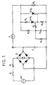
- the output terminal of a rectifier bridge D is connected in series with a lamp L and a resistor R2.
- the resistor R2 acts to limit surge current and is connected in parallel with a main controlled rectifier SCR2.
- a secondary controlled rectifier SCR1 which operates with a relatively small current is connected by way of a resistor R3 between the anode and the gate of the main controlled rectifier SCR2.
- a resistor R5 and a capacitor C2 form a delay circuit having a time constant, and, on closing a power switch S1, conduction of the secondary controlled rectifier SCR1 is delayed in accordance with the time constant.
- the filament of lamp L is preheated during this delay period, and the resistance of the filament increases to its steady state level by the time when the resistor R2 will be short-circuited.
- the voltage on the capacitor C2 triggers the secondary controlled rectifier SCR1.
- the conduction current of the secondary controlled rectifier SCR1 instantly energizes the main controlled rectifier SCR2 which short-circuits the resistor R2.
- the output of the rectifier bridge D is smoothed by a capacitor C1, and supplied to the lamp L instantly on short-circuit of the resistor R2.
- the voltage across the controlled rectifier energizes the delay circuit to keep the main and the secondary controlled rectifiers SCR2 and SCR1 conductive.
- the gate current of the secondary controlled rectifier SCR1 can be suppressed to 1 milliampere or less.
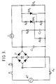
- the time constant of a few one-tenths of a second can be obtained by omitting the secondary controlled rectifier SCR1 as shown in FIG. 2, and using resistors R5 and R6 (total resistance of 3 kiloohms) and capacitor C3 (2,000 microfarads).
- resistors R5 and R6 total resistance of 3 kiloohms
- capacitor C3 2,000 microfarads
- the conduction of the main controlled rectifier can be stably controlled without causing gate overheating even as the triggering voltage of the main controlled rectifier varies with the ambient temperature.
- a device directed for use in a cold environment can be stably used at a relatively high temperature.
- the resistor R1 connected at the ac side of the rectifier bridge D is generally set to about 0.5 to 3 ohms to limit any arc discharge current which may arise on the outage of lamp L during dc illumination. This prevents the possibility of damage to circuit elements such as the diodes and the controlled rectifiers.
- FIG. 3 illustrates another embodiment of a device of the invention.
- the positive output terminal of the rectifier bridge D is used as the source to charge the delay circuit.
- this embodiment is arranged to cause a loss to the arc discharge current that may arise on the outage of lamp L during dc illumination by connecting low resistor R1 in series with the ac side of rectifier bridge D in order to prevent a possible damage of the circuit elements such as diode and controlled rectifiers.
- surge current into the lamp can be limited without causing overheating of the controlled rectifier even when the triggering voltage of the controlled rectifier may vary with the ambient temperature.
- the conduction current of the secondary controlled rectifier never increases to a level which overheats the gate of the main controlled rectifier to cause its destruction.
- a device of the invention is simple but very effective in the limitation of surge current, the device can be used advantageously in illumination using an incandescent lamp or a power source therefor.
Landscapes
- Circuit Arrangement For Electric Light Sources In General (AREA)
- Emergency Protection Circuit Devices (AREA)
- Rectifiers (AREA)
Claims (6)
- Vorrichtung zur Begrenzung des Einschaltstroms in einer Glühlampe, die aufweist:- einen ersten Widerstand, der mit der Glühlampe in einer Stromversorgungsschaltung zur Begrenzung des Einschaltstroms in der Glühlampe in Serie geschaltet ist,- eine torgesteuerte Gleichrichterschaltung mit einem Hauptstrompfad, der parallel mit dem Widerstand geschaltet ist, und- einer Verzögerungschaltung, die an die Stromversorgungsschaltung zum Betrieb der gesteuerten Gleichrichterschaltung nach einer Zeitverzögerung angeschlossen ist,dadurch gekennzeichnet,
daß zur Stabilisierung des Betriebs der gesteuerten Gleichrichterschaltung bei einer Änderung der Umgebungstemperatur und zur Vermeidung einer Torüberhitzung in der gesteuerten Schaltung die Schaltung aufweist:- einen ersten gesteuerten Gleichrichter, der den Hauptstrompfad über den ersten Widerstand ermöglicht, und- einen zweiten gesteuerten Gleichrichter mit einem Tor, das mit der Verzögerungsschaltung verbunden ist, und einem Ausgang, der an ein Tor des ersten gesteuerten Gleichrichters angeschlossen ist, wobei der zweite gesteuerte Gleichrichter bei einem relativ geringen Strom betriebsbereit ist im Vergleich zu dem ersten gesteuerten Gleichrichter, um hierdurch ein unerwünschtes Aufheizen des Toren des ersten gesteuerten Gleichrichters zu vermeiden. - Vorrichtung nach Anspruch 1,
dadurch gekennzeichnet,
daß die Stromquelle (D) aufweist:- eine Gleichrichtereinrichtung (D), deren Wechselstromseite zum Anschluß an eine Wechselstromquelle (AC) vorgesehen ist, und deren Gleichstromseite zum Anschluß an die Glühlampe (L) vorgesehen ist, und- eine zweite Widerstandseinrichtung (R₁) zur Begrenzung des Lichtbogenentladungsstroms, der bei Ausfall der Glühlampe (L) auftreten kann, wenn diese noch an die Gleichrichtereinrichtung (D) angeschlossen ist, wobei die zweite Widerstandseinrichtung (R₁) zwischen die Wechselstromquelle (AC) und die Wechselstromseite der Gleichrichtereinrichtung (D) geschaltet ist. - Vorrichtung nach Anspruch 1 oder 2,
dadurch gekennzeichnet,
daß es sich bei dem ersten und dem zweiten gesteuerten Gleichrichter um rückwärtssperrende Trioden-Thyristoren handelt. - Vorrichtung nach einem der vorangehenden Ansprüche,
dadurch gekennzeichnet,
daß die Verzögerungsschaltung aus einer Widerstands-/Kondensator-Zeitkonstantenschaltung (R₅, C₂) gebildet ist. - Vorrichtung nach Anspruch 4,
dadurch gekennzeichnet,
daß die Widerstands-/Kondensator-Zeitkonstantenschaltung einen Widerstand und eine Kapazität in Reihe aufweist, und die Zeitkonstantenschaltung sowohl mit dem ersten als auch mit dem zweiten gesteuerten Gleichrichter parallelgeschaltet ist, wobei das Tor des zweiten gesteuerten Gleichrichters zwischen den Widerstand und die Kapazität der Zeitkonstantenschaltung geschaltet ist. - Vorrichtung nach einem der Ansprüche 2 bis 4,
dadurch gekennzeichnet,
daß die Gleichrichtereinrichtung (D) aus einem Vollweg-Gleichrichter mit einer Glättungseinrichtung (C₁) an seiner Gleichstromseite besteht.
Applications Claiming Priority (2)
| Application Number | Priority Date | Filing Date | Title |
|---|---|---|---|
| JP61027513A JPS62185516A (ja) | 1986-02-10 | 1986-02-10 | 突入電流制限装置 |
| JP27513/86 | 1986-02-10 |
Publications (2)
| Publication Number | Publication Date |
|---|---|
| EP0242022A1 EP0242022A1 (de) | 1987-10-21 |
| EP0242022B1 true EP0242022B1 (de) | 1992-08-12 |
Family
ID=12223208
Family Applications (1)
| Application Number | Title | Priority Date | Filing Date |
|---|---|---|---|
| EP87300995A Expired - Lifetime EP0242022B1 (de) | 1986-02-10 | 1987-02-04 | Vorrichtung zur Begrenzung von Stromstössen |
Country Status (7)
| Country | Link |
|---|---|
| US (1) | US4800329A (de) |
| EP (1) | EP0242022B1 (de) |
| JP (1) | JPS62185516A (de) |
| KR (1) | KR900008980B1 (de) |
| BR (1) | BR8700508A (de) |
| CA (1) | CA1296759C (de) |
| DE (1) | DE3781004T2 (de) |
Families Citing this family (20)
| Publication number | Priority date | Publication date | Assignee | Title |
|---|---|---|---|---|
| JPH0762812B2 (ja) * | 1987-04-18 | 1995-07-05 | 林原 健 | ランプ点燈用電源装置 |
| JP2779938B2 (ja) * | 1988-09-08 | 1998-07-23 | 林原 健 | 照明装置 |
| TW203145B (de) * | 1991-04-09 | 1993-04-01 | Hayashibara Ken | |
| DE4121055C2 (de) * | 1991-06-26 | 1994-12-15 | Ute Koechling | Schaltungsanordnung zur Einschaltstrombegrenzung von Glühlampen |
| KR100259240B1 (ko) * | 1991-12-06 | 2000-06-15 | 하야시바라 겐 | 조명장치 |
| US5287263A (en) * | 1992-07-01 | 1994-02-15 | Digital Equipment Corporation | Inrush current control circuit |
| US5420780A (en) * | 1993-12-30 | 1995-05-30 | Omega Power Systems | Apparatus for limiting inrush current |
| KR19990002105A (ko) * | 1997-06-19 | 1999-01-15 | 배순훈 | 기계식 전자렌지의 돌입전류 방지회로 |
| US6426885B1 (en) | 1999-10-06 | 2002-07-30 | Hitachi, Ltd. | Inverter device and motor driving device provided with inrush current prevention circuit |
| KR20010016094A (ko) * | 2000-11-01 | 2001-03-05 | 김기대 | 형광등제어장치 |
| US6411045B1 (en) | 2000-12-14 | 2002-06-25 | General Electric Company | Light emitting diode power supply |
| TW522623B (en) * | 2001-06-13 | 2003-03-01 | Delta Electronics Inc | Inrush current protection circuit |
| US20040169981A1 (en) * | 2002-09-19 | 2004-09-02 | Andy Werback | Current limiting circuit |
| NL1029768C2 (nl) * | 2005-08-19 | 2007-02-20 | Martinus Cornelis Van De Groep | Voorschakelinrichting. |
| TW200737677A (en) * | 2006-03-24 | 2007-10-01 | Hon Hai Prec Ind Co Ltd | Power supply device with inrush current limiting circuit |
| WO2008098613A1 (de) * | 2007-02-13 | 2008-08-21 | Osram Gesellschaft mit beschränkter Haftung | Led-modul und verfahren zum betreiben mindestens einer led |
| KR100974213B1 (ko) * | 2008-08-12 | 2010-08-06 | 주식회사 하이닉스반도체 | 전원 잡음 검출 장치 및 이를 이용한 전원 잡음 제어 장치 |
| US8422179B2 (en) * | 2009-07-22 | 2013-04-16 | Intersil Americas Inc. | Inrush current control |
| KR101561341B1 (ko) * | 2013-09-02 | 2015-10-16 | 엘에스산전 주식회사 | 역률 보상 회로 |
| CA3153001A1 (en) | 2019-08-28 | 2021-03-04 | SparkCharge, Inc. | Electric vehicle charging apparatus, system and methods |
Family Cites Families (7)
| Publication number | Priority date | Publication date | Assignee | Title |
|---|---|---|---|---|
| US3793581A (en) * | 1972-04-19 | 1974-02-19 | Us Navy | Solid state phase controlled switch |
| JPS5178684A (ja) * | 1974-12-30 | 1976-07-08 | Meidensha Electric Mfg Co Ltd | Handotaisochi |
| DE2741186C3 (de) * | 1977-09-13 | 1981-02-26 | Siemens Ag, 1000 Berlin Und 8000 Muenchen | Elektrische Schaltung, durch die die Spannung an einem Verbraucher nach dem Einschalten verzögert ansteigt |
| US4207516A (en) * | 1978-08-28 | 1980-06-10 | Rca Corporation | Switching regulator with reduced inrush current |
| US4570108A (en) * | 1982-07-06 | 1986-02-11 | Stroede Aake | Protection device for electrical incandescent lamps |
| JPS59230298A (ja) * | 1983-06-14 | 1984-12-24 | 林原 健 | 突入電流排除装置 |
| US4654579A (en) * | 1984-08-17 | 1987-03-31 | Ken Hayashibara | Frequency divider |
-
1986
- 1986-02-10 JP JP61027513A patent/JPS62185516A/ja active Pending
-
1987
- 1987-01-06 CA CA000526736A patent/CA1296759C/en not_active Expired - Lifetime
- 1987-01-21 KR KR1019870000439A patent/KR900008980B1/ko not_active Expired
- 1987-02-04 DE DE8787300995T patent/DE3781004T2/de not_active Expired - Fee Related
- 1987-02-04 EP EP87300995A patent/EP0242022B1/de not_active Expired - Lifetime
- 1987-02-05 BR BR8700508A patent/BR8700508A/pt not_active IP Right Cessation
-
1988
- 1988-05-23 US US07/198,487 patent/US4800329A/en not_active Expired - Lifetime
Non-Patent Citations (1)
| Title |
|---|
| SCR Manual, General Electric Co; New York 1979; pages 227-228 * |
Also Published As
| Publication number | Publication date |
|---|---|
| JPS62185516A (ja) | 1987-08-13 |
| KR870008488A (ko) | 1987-09-26 |
| DE3781004T2 (de) | 1993-03-25 |
| US4800329A (en) | 1989-01-24 |
| DE3781004D1 (de) | 1992-09-17 |
| KR900008980B1 (ko) | 1990-12-15 |
| EP0242022A1 (de) | 1987-10-21 |
| CA1296759C (en) | 1992-03-03 |
| BR8700508A (pt) | 1987-12-08 |
Similar Documents
| Publication | Publication Date | Title |
|---|---|---|
| EP0242022B1 (de) | Vorrichtung zur Begrenzung von Stromstössen | |
| US6111368A (en) | System for preventing oscillations in a fluorescent lamp ballast | |
| US5883473A (en) | Electronic Ballast with inverter protection circuit | |
| US7321201B2 (en) | Basic halogen convertor IC | |
| US4719399A (en) | Quick discharge motor starting circuit | |
| JP4951069B2 (ja) | 電流制限されたrms電圧調整された出力を有するパワーコントローラ | |
| US4204148A (en) | Regulation circuit | |
| US4855649A (en) | Single-wired switching circuit directed to limit surge into lamp | |
| US12513801B2 (en) | Power converter for converting an input to an output for driving a load, as well as a corresponding LED based lighting device and a corresponding method | |
| US4209738A (en) | Regulation circuit | |
| US6788023B2 (en) | Motor starter circuit, particularly for refrigerator compressors | |
| JPH0530729A (ja) | 整流回路の切換え回路 | |
| EP0254506B1 (de) | Schaltung zur Begrenzung von Überspannungen in gleichstrombetriebenen Lampen | |
| JP2507825Y2 (ja) | 照明装置 | |
| JPH0210699A (ja) | 点灯装置 | |
| KR850000103Y1 (ko) | 유도 전동기의 부하전력제어 회로 | |
| US4710698A (en) | Phase-controlled automatic switching circuit | |
| KR100297001B1 (ko) | 전열기기제어회로 | |
| KR0151539B1 (ko) | 형광등용 전자식 스타터 | |
| SU1072234A1 (ru) | Устройство дл управлени коммутатором трехфазной нагрузки | |
| WO1996022007A1 (en) | Electronic starter for fluorescent lamp | |
| KR900005496Y1 (ko) | 난방기구의 초기돌입전류 제한회로 | |
| KR0129656Y1 (ko) | 형광등 점등장치 | |
| KR950003488Y1 (ko) | 돌입 전류(Inrush current)제한회로 | |
| JPH0547483A (ja) | 放電灯点灯装置 |
Legal Events
| Date | Code | Title | Description |
|---|---|---|---|
| PUAI | Public reference made under article 153(3) epc to a published international application that has entered the european phase |
Free format text: ORIGINAL CODE: 0009012 |
|
| AK | Designated contracting states |
Kind code of ref document: A1 Designated state(s): DE FR GB |
|
| 17P | Request for examination filed |
Effective date: 19880422 |
|
| 17Q | First examination report despatched |
Effective date: 19891010 |
|
| GRAA | (expected) grant |
Free format text: ORIGINAL CODE: 0009210 |
|
| AK | Designated contracting states |
Kind code of ref document: B1 Designated state(s): DE FR GB |
|
| REF | Corresponds to: |
Ref document number: 3781004 Country of ref document: DE Date of ref document: 19920917 |
|
| ET | Fr: translation filed | ||
| PLBE | No opposition filed within time limit |
Free format text: ORIGINAL CODE: 0009261 |
|
| STAA | Information on the status of an ep patent application or granted ep patent |
Free format text: STATUS: NO OPPOSITION FILED WITHIN TIME LIMIT |
|
| 26N | No opposition filed | ||
| REG | Reference to a national code |
Ref country code: GB Ref legal event code: IF02 |
|
| PGFP | Annual fee paid to national office [announced via postgrant information from national office to epo] |
Ref country code: GB Payment date: 20030205 Year of fee payment: 17 |
|
| PGFP | Annual fee paid to national office [announced via postgrant information from national office to epo] |
Ref country code: FR Payment date: 20030226 Year of fee payment: 17 |
|
| PGFP | Annual fee paid to national office [announced via postgrant information from national office to epo] |
Ref country code: DE Payment date: 20030327 Year of fee payment: 17 |
|
| PG25 | Lapsed in a contracting state [announced via postgrant information from national office to epo] |
Ref country code: GB Free format text: LAPSE BECAUSE OF NON-PAYMENT OF DUE FEES Effective date: 20040204 |
|
| PG25 | Lapsed in a contracting state [announced via postgrant information from national office to epo] |
Ref country code: DE Free format text: LAPSE BECAUSE OF NON-PAYMENT OF DUE FEES Effective date: 20040901 |
|
| GBPC | Gb: european patent ceased through non-payment of renewal fee |
Effective date: 20040204 |
|
| PG25 | Lapsed in a contracting state [announced via postgrant information from national office to epo] |
Ref country code: FR Free format text: LAPSE BECAUSE OF NON-PAYMENT OF DUE FEES Effective date: 20041029 |
|
| REG | Reference to a national code |
Ref country code: FR Ref legal event code: ST |