EP0241982B1 - Streuer und Verfahren, um das Streugut zu sammeln - Google Patents
Streuer und Verfahren, um das Streugut zu sammeln Download PDFInfo
- Publication number
- EP0241982B1 EP0241982B1 EP19870200625 EP87200625A EP0241982B1 EP 0241982 B1 EP0241982 B1 EP 0241982B1 EP 19870200625 EP19870200625 EP 19870200625 EP 87200625 A EP87200625 A EP 87200625A EP 0241982 B1 EP0241982 B1 EP 0241982B1
- Authority
- EP
- European Patent Office
- Prior art keywords
- collector
- spreader
- around
- members
- dosing
- Prior art date
- Legal status (The legal status is an assumption and is not a legal conclusion. Google has not performed a legal analysis and makes no representation as to the accuracy of the status listed.)
- Expired - Lifetime
Links
- 239000000463 material Substances 0.000 title claims description 51
- 238000000034 method Methods 0.000 title claims description 6
- 230000005540 biological transmission Effects 0.000 claims description 12
- 230000008878 coupling Effects 0.000 claims description 12
- 238000010168 coupling process Methods 0.000 claims description 12
- 238000005859 coupling reaction Methods 0.000 claims description 12
- 238000007789 sealing Methods 0.000 claims description 12
- 239000003337 fertilizer Substances 0.000 claims description 2
- 238000010276 construction Methods 0.000 description 3
- 239000002689 soil Substances 0.000 description 2
- 230000000694 effects Effects 0.000 description 1
- 239000008187 granular material Substances 0.000 description 1
Images

Classifications
-
- A—HUMAN NECESSITIES
- A01—AGRICULTURE; FORESTRY; ANIMAL HUSBANDRY; HUNTING; TRAPPING; FISHING
- A01C—PLANTING; SOWING; FERTILISING
- A01C17/00—Fertilisers or seeders with centrifugal wheels
- A01C17/006—Regulating or dosing devices
-
- A—HUMAN NECESSITIES
- A01—AGRICULTURE; FORESTRY; ANIMAL HUSBANDRY; HUNTING; TRAPPING; FISHING
- A01C—PLANTING; SOWING; FERTILISING
- A01C7/00—Sowing
- A01C7/08—Broadcast seeders; Seeders depositing seeds in rows
- A01C7/10—Devices for adjusting the seed-box ; Regulation of machines for depositing quantities at intervals
- A01C7/107—Calibration of the seed rate
Definitions
- the invention relates to device for spreading material, in particular for spreading granular and/or pulverulent material, such as fertilizer, comprising a frame, a hopper having an outlet with a dosing member, at least one spreader member and a collector having a coupling member by means of which it is coupled detachably to the device, the collector enclosing a wall located at the pheriphery of the spreader member and at a relatively short distance therefrom.
- a device of this kind is known from NL-A-273620.
- the member comprises a wall located at the periphery of the spreader member to collect and guide the material to two outlet openings for spreading the material more or less radially in two opposite directions. It is an object of the invention to provide a simple device of the above-defined type, with the collector of which the material can be collected and delivered in a collector bin.
- the collector has a slotted aperture which fits around a transmission box enclosing means for driving the spreading member, said slotted aperture being provided with flexible seals which can pass along the transmission box, the collector member having a removable cover the inner edge of which is provided with a seal joining the dosing member, the collector enclosing at its lower side an open end for delivering the collected material in a collector bin.
- the seals between the collector member and the other parts of the device prevent material from being discharged without being delivered in the collector bin.
- the material delivered from the hopper by means of the dosing member and spread by the spreader member in the collector member can be collected in an advantageous way to measure the quantity of material which will flow through the dosing member during e.g. a unit of time.
- the construction of the collector member may be simple and easy to handle by coupling with or detaching same from the device, respectively.
- the cover has two contiguous portions, each provided with a sealing edge, said portions being applicable to the collector member or removable therefrom independently of each other.
- the coupling member comprises a hook which is connectable with a tight fit on a holder which is rigidly connected to the frame.
- said method is characterized in that the blades are removed from the spreader member prior to mounting the collector around the spreader member, that the period of time is predetermined and that the material collected by the collector is delivered in a collector bin to determine the quantity of material discharged in the predetermined period in order to determine the quantity of material discharged per unit of time via the dosing member. Since the spreader blades have been removed, the material is thrown away against the collecting wall of the collector member with a low force, so that the structure of the material will not be affected and the material will be suitable again for spreading.
- the DE-C-89685 shows a known construction of a guide member with which the material spread by the spreader member can be divided evenly over the ground within the wheel tracks of the spreader. This known guide member does not collect the material to be delivered in a collector bin.
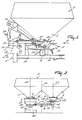
- the device for spreading material shown in the drawings comprises a frame 1, to which a hopper 2 is mounted.
- the hopper 2 has two discharge nozzles 3 and 4 which are arranged spaced from each other and transversely to the direction of normal operative travel 25 of the device, and below which spreader members 5 and 6 are arranged.
- Dosing members 7 and 8 are located between the discharge nozzles 3 and 4 and the respective spreader members 5 and 6.
- the spreader members 5 and 6 are pivotally bearing-supported in gear boxes 9 and 10, which are intercoupled by a box-like transmission box 11 having in its interior transmission members arranged between the two gear boxes 9 and 10.
- a gear box 12 having a coupling shaft 17 is provided halfway between the two gear boxes 9 and 10.
- the frame comprises a vertical frame portion 13 fitted with coupling members 14 and 15, by means of which the device can be coupled to the lifting hitch of a tractor or similar suchlike vehicle.
- the frame 1 furthermore comprises a supporting beam 16 which, when the device is in the upright position, is in a substantially horizontal position.
- the supporting beam 16 is in the shape of a V, not further shown, and by means of the ends of the V-shaped, forwardly diverging legs connects to vertical beams of said frame portion 13.
- the lower beam 16 has a rectangular cross-section.
- Each of the dosing members 7 and 8 comprises a discharge member 20, which is shown in greater detail in Figure 4 for the dosing member 7, and which in this embodiment is annular and has walls that are curved in accordance with a segment of a sphere.
- each of the discharge members 20 has two discharge outlets 21 and 22.
- a slide 23, by means of which the discharge outlets 21 and 22 can be closed optionally to a greater or lesser extent, is movably provided to the outer side of the discharge member 20.
- the slide 23 is coupled to an adjusting mechanism 24, which is not further shown, but by means of which the slide can be set and optionally be moved to a desired position for closing the discharge outlets to a greater or lesser extent.
- the discharge outlets 21 and 22 in the discharge members 20 of the two dosing members 7 and 8 are located symmetrically with respect to a vertical centre plane 24 extending in the normal direction of operative travel 25 of the device and constituting a plane of symmetry.
- the spreader members 5 and 6 are rotatable around the axes of rotation 28 and 29 which, when the machine is in an upright position as shown in Figure 1, are vertical.
- the spreader members are rotatably bearing-supported in the gear boxes 9 and 10 and are coupled to transmission members located in the gear boxes 9 and 10, the transmission box 11 and the gear box 12.
- each of the spreader members 5 and 6 has a plate-shaped portion 30, on which spreader blades 31 are mounted.
- Each of the spreader members 5 and 6 has a supporting disc 32 which is pivotally connected to the spreader member.
- the supporting disc 32 has a supporting edge 33 bearing the bottom side of the discharge member 20, as is apparent in particular from Figure 4.
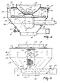
- the device includes a collector member 36 which is shown in greater detail in the Figures 3 to 5 and, in this embodiment, surrounds the spreader member 5.
- the collector member 36 has a cylindrical collecting wall 37, the lower side 38 of which is located at the level of the lower side of the spreader member 5. By means of its lower side the collecting wall 37 is contiguous to a conical, downwardly tapering guide member 39, whose lower side has an open cylindrical end 40.
- the collector member 36 has a coupling member 41 connected thereto by means of supporting members 42.
- the coupling member 41 is constituted by a U-shaped pipe having legs 43 and 44 which are parallel to each other.
- the legs 43 and 44 of the coupling member are provided at their ends with hooks 45 and 46 of an angular cross-section.
- Said hooks are constituted by U-shaped strip material and have a long leg and a short one.
- the hooks 45 and 46 are provided with a close fit over a leg of the lower beam 16, as is apparent from the Figures 3, 4 and 5.
- a slotted aperture 47 of a width 48 is made in the cylindrical collecting wall 37 and in part of the conical guide wall 39.
- Flexible guide means 51 and 52 constituted in this embodiment by hair-shaped, flexible sealing members, are provided on the vertically extending sides 49 and 50 of said slotted aperture.
- Each of said sealing members has hair-shaped projections extending from the relevant side 49 or 50 to halfway the width 48 of said slotted aperture 47.
- the collector member 36 has a cover 53 consisting of two substantially identical parts 54.
- the cover 53 has an inner edge 55 extending with some clearance around the discharge member 20.
- the inner edge 55 of the cover halves 54 have flexible sealing edges 34 which, like the sealing members 51 and 52, consist of hair-shaped projections 35 extending from the inner edge 55 to the periphery of the discharge member 20. These hair-shaped sealing members 35 are flexible and constitute a flexible seal between the upper side of the collector member 36 and the discharge member 20.
- the device is coupled to the lifting hitch of a tractor or similar suchlike vehicle with the aid of connecting members 14 and 15.
- the power take-off shaft of the tractor is coupled to the coupling shaft 17 of the transmission gear box 12, so that the power take-off shaft of the tractor causes the spreader members 5 and 6 to rotate.
- the transmission members in the various gear and transmission boxes are such that, during operation, the spreader members are brought to rotation in directions opposite to each other.
- the device will be moved in the direction 25.
- the outlets 21 and 22 have been provided such, and the spreader members 5 and 6 are formed and driven such that each of the spreader members distributes the material over the full width of the strip of soil on which the material is spread during operation. During normal operation, this strip of soil will extend equidistantly on either side of the centre plane 24 extending in the direction of operative travel 25.
- the quantity of material which, depending on the rate of travel, the spreading width and the quantity to be spread per unit of area, is to flow from the outlets 21 and 22 of the respective dosing members 7 and 8 can be controlled by closing said outlets to a greater or lesser extent by means of the slides 23.
- the collector member 36 can be positioned around one of the spreader members 5 or 6, the arrangement being such as is shown in the drawings wherein the collector member 36 surrounds the spreader member 5. Prior to the positioning of the collector member around the spreader member, the blades 31 are removed from the spreader member concerned, as is apparent from Figure 4.
- the wall 37 has such a cylindrical circumference that it surrounds the plate-shaped portion 30 of the spreader member.
- the wall 37 is placed at a distance 56 from the periphery of the plate-shaped member 30.
- the distance 56 is equal to approximately 1/12th part of the diameter 57 of the plate-shaped member 30.
- the distance 56 may alternatively be somewhat greater or smaller, the distance 56 will be chosen such that the collector member 36 can be of a relatively small size and the material can flow downwards between the collecting wall 37 and the periphery of the plate-shaped member 30.
- the distance 56 will not be greater than approximately 1/6th of the diameter 57. In this embodiment, said distance is approximately 40 mms and it is preferred not to exceed approximately 70 mms.
- the minimum distance 56 can be chosen such that the wall 37 is just sufficiently free from the periphery of the plate-shaped member 30 to allow the material to pass.
- the sealing edges 51 and 52 are provided at the inner side of the wall 37, as is apparent from Figure 4. If so desired, it is possible to connect the sealing members 51 and 52 to the outer side of the cylindrical wall 37 along the edges 49 and 50.
- the collector member 36 can be fastened in a simple manner to the frame by omitting the cover 53 from its upper side and thereafter hooking same around the upper side of the lower beams 16 by means of the hooks 45 and 46, as is shown in the drawings.
- the hooks 45 and 46 fit around the beam 16.
- the beam 16 constitutes a holder for the hooks 45 and 46.
- the hooks 45 and 46 may be of a different shape and separate holders may be provided on the beam 16.
- the collector member 36 can be mounted from the lower side of the transmission box 11 by sliding the slotted aperture 47 over the box 11. Thereafter, when the wall 37 is approximately centered around the plate 30, the hooks 45 and 46 can be placed over the beam 16.
- the cover halves 54 can be placed around the discharge member 20 and on the top side of the collecting wall 37. At the contiguous halves 54, the cover 53 is provided with a centering edge 59, which bears on the inner side of the collecting wall 37.
- the material can be discharged from the discharge nozzle 3.
- the discharge outlets can be closed by the slide 23, so that the quantity of material flown out from the outlets 21 and 22 per unit of time can be established, and also whether said quantity corresponds to the desired quantity of material to be spread per unit of time.
- the hair-shaped, flexible sealing edges 34 and 35 of the cover and the edges 51 and 52 of the slotted aperture 47 ensure that, during this test, no material is lost without being collected in the collector bin.
- the flexible sealing edges facilitate the mounting of the collector member on the device and the removal of same therefrom. The test having been completed, the collector member 36 can be removed again from the device, whereafter the blades 31 are re-mounted on the plate-shaped member 30. Then the device is ready for the spreading of material.
- the material to be spread is loaded in the hopper 2 and is fed to the spreader members 5 and 6 via the discharge outlets 21 and 22 of the dosing members 7 and 8, which outlets are closed to a greater or lesser extent by the slides 23. Said spreader members will spread the material over the desired width, the device travelling at a desired speed in the direction indicated by the arrow 25. Because of the previously made test to establish the required passage size in the discharge outlets 21 and 22, it is possible to accurately determine the spread of the desired quantity of material for each hectare. By removing, during the flow test using the collector member 36, the spreader blade 31 from the plate-shaped portion 30, the material will not be flung with an excessively high force against the wall 37. In this manner, it can be accomplished that the grain structure of in particular granular material will not be damaged. Consequently, the material flowing from the hopper during the test can be used again for spreading on the surface to be spread, so that this quantity of material does not get lost.
- the collector member according to the invention and in accordance with the embodiment shown in the drawings, can be kept very simple as regards its construction and can be easily connected to the machine.
- the quantity of material flowing out per unit of time can be checked advantageously and collected for re-use by means of the method described in the foregoing, in which method the blades are removed from the plate-shaped member 30.
- the device is substantially symmetrical relative to the plane 24. This renders it possible for the collector member 36 to be alternatively arranged around the spreader member 6 instead of around the spreader member 5.
- the collecting wall 37 is cylindrical in shape, it may also be of a different shape.
Landscapes
- Life Sciences & Earth Sciences (AREA)
- Soil Sciences (AREA)
- Environmental Sciences (AREA)
- Fertilizing (AREA)
- Catching Or Destruction (AREA)
Claims (8)
- Streugerät, insbesondere zum Streuen von körnigem und/oder pulverigem Gut, wie z. B. Kunstdünger, mit einem Rahmen (1), einem Vorratsbehälter (2), der einen mit einem Dosierer (7, 8) versehenen Auslaß (21, 22) hat, mindestens einem Streuglied (5, 6) und einem Kollektor (36) mit einem Verbindungsglied (41), mittels dessen er mit dem Gerät lösbar verbunden ist, wobei der Kollektor (36) eine Wandung (37) aufweist, die mit geringem Abstand von dem Streuglied (5) nahe dessen Peripherie angeordnet ist,
dadurch gekennzeichnet, daß der Kollektor eine schlitzförmige Öffnung (47) hat, die ein den Antrieb des Streugliedes umschließendes Getriebegehäuse (11) umgibt, wobei die schlitzförmige Öffnung mit flexiblen Dichtungen (51 und 52) versehen ist, die an dem Getriebegehäuse entlangzubewegen sind, und wobei der Kollektor (36) einen abnehmbaren Deckel (53) hat, dessen innerer Rand (55) eine an dem Dosierer (7, 8) anliegende Dichtung (34) aufweist, und wobei der Kollektor an seiner unteren Seite ein offenes Ende (40) zur Abgabe des gesammelten Gutes in einen Sammelbehälter (60) hat. - Gerät nach Anspruch 1,
dadurch gekennzeichnet, daß der Deckel (53) zwei aneinander anliegende Teile (54) hat, die jeweils mit einem Teil eines Dichtungsrandes versehen sind, wobei die Teile unabhängig voneinander an dem Kollektor (41) anzubringen und von ihm abzunehmen sind. - Gerät nach Anspruch 1 oder 2,
dadurch gekennzeichnet, daß die flexiblen Dichtungen (34, 51, 52) durch bürstenartige Vorrichtungen gebildet sind. - Gerät nach einem der vorhergehenden Ansprüche,
dadurch gekennzeichnet, daß die Kollektorwandung (37) zylinderförmig ausgebildet ist und an ihrer unteren Seite in eine Führung (39) übergeht, die sich zur Ausrichtung auf den Sammelbehälter nach unten verjüngt und in dem offenen Ende ausläuft. - Gerät nach einem der vorhergehenden Ansprüche,
dadurch gekennzeichnet, daß das Verbindungsglied mindestens einen Haken (45, 46) aufweist, der mit festem Sitz an einem Halter (16) anzubringen ist, der mit dem Rahmen starr verbunden ist. - Gerät nach Anspruch 5,
dadurch gekennzeichnet, daß das Verbindungsglied (41) einen Träger aufweist, der den Kollektor (36) zumindest teilweise umgreift, und an dem zwei Haken (45, 46) angeordnet sind, die mit festem Sitz an einem Rahmenbalken (16) anzubringen sind. - Gerät nach einem der vorhergehenden Ansprüche,
dadurch gekennzeichnet, daß das Gerät zwei Streuglieder (5, 6) aufweist und im wesentlichen symmetrisch zu seiner vertikalen Mittelebene ausgebildet ist, wobei der Kollektor (36) alternativ derart anzubringen ist, daß er eines der beiden Streuglieder (5, 6) umschließt. - Verfahren zur Verwendung des Gerätes nach einem der vorhergehenden Ansprüche, wobei der Kollektor (36) um den mit Wurfschaufeln (31) versehenen Streuglied (5, 6) angebracht ist und das Gut während eines Zeitraumes und bei einer gewünschten Einstellung des Dosierers (7, 8) aus dem Vorratsbehälter über den Dosierer zu dem Streuglied befördert, über das Streuglied ausgebracht und anschließend von dem Kollektor aufgefangen wird,
dadurch gekennzeichnet, daß die Schaufeln vor Anbringen des Kollektors um den Streuglied von dem Streuglied entfernt werden, daß der Zeitraum vorgegeben ist, und daß das von dem Kollektor aufgefangene Gut in einen Sammelbehälter (60) abgegeben wird, um die während des vorgegebenen Zeitraumes ausgebrachte Gutmenge und damit die pro Zeiteinheit über den Dosierer ausgebrachte Gutmenge zu bestimmen.
Applications Claiming Priority (2)
| Application Number | Priority Date | Filing Date | Title |
|---|---|---|---|
| NL8600868A NL8600868A (nl) | 1986-04-07 | 1986-04-07 | Inrichting voor het verspreiden van materiaal en werkwijze voor het opvangen van materiaal. |
| NL8600868 | 1986-04-07 |
Publications (2)
| Publication Number | Publication Date |
|---|---|
| EP0241982A1 EP0241982A1 (de) | 1987-10-21 |
| EP0241982B1 true EP0241982B1 (de) | 1994-08-24 |
Family
ID=19847834
Family Applications (1)
| Application Number | Title | Priority Date | Filing Date |
|---|---|---|---|
| EP19870200625 Expired - Lifetime EP0241982B1 (de) | 1986-04-07 | 1987-04-03 | Streuer und Verfahren, um das Streugut zu sammeln |
Country Status (3)
| Country | Link |
|---|---|
| EP (1) | EP0241982B1 (de) |
| DE (1) | DE3750412T2 (de) |
| NL (1) | NL8600868A (de) |
Families Citing this family (7)
| Publication number | Priority date | Publication date | Assignee | Title |
|---|---|---|---|---|
| NL8702290A (nl) * | 1987-09-25 | 1989-04-17 | Lely Nv C Van Der | Meetinrichting voor een machine voor het verspreiden van materiaal. |
| DE3919396A1 (de) * | 1989-06-14 | 1990-12-20 | Amazonen Werke Dreyer H | Zentrifugalduengerstreuer |
| NL8901903A (nl) * | 1989-07-24 | 1991-02-18 | Lely Nv C Van Der | Machine voor het verspreiden van materiaal. |
| DK0427935T3 (da) * | 1989-11-03 | 1995-10-16 | Amazonen Werke Dreyer H | Fremgangsmåde til anvendelse af en centrifugalgødningsspreder |
| DE4105046C2 (de) * | 1991-01-18 | 1999-07-01 | Amazonen Werke Dreyer H | Meßvorrichtung zur Ermittlung des Reibrollverhaltens von Düngerkörnern |
| US8727182B2 (en) | 2011-02-24 | 2014-05-20 | The Procter & Gamble Company | Feeder for particle delivery |
| CN117502348B (zh) * | 2023-12-13 | 2024-05-17 | 连云港正大农牧发展有限公司 | 一种渔业饲料投放装置 |
Family Cites Families (3)
| Publication number | Priority date | Publication date | Assignee | Title |
|---|---|---|---|---|
| DE89685C (de) * | ||||
| NL273620A (de) * | 1900-01-01 | |||
| NL6913057A (de) * | 1969-08-27 | 1971-03-02 |
-
1986
- 1986-04-07 NL NL8600868A patent/NL8600868A/nl not_active Application Discontinuation
-
1987
- 1987-04-03 EP EP19870200625 patent/EP0241982B1/de not_active Expired - Lifetime
- 1987-04-03 DE DE19873750412 patent/DE3750412T2/de not_active Expired - Fee Related
Also Published As
| Publication number | Publication date |
|---|---|
| NL8600868A (nl) | 1987-11-02 |
| EP0241982A1 (de) | 1987-10-21 |
| DE3750412T2 (de) | 1995-04-20 |
| DE3750412D1 (de) | 1994-09-29 |
Similar Documents
| Publication | Publication Date | Title |
|---|---|---|
| EP0053419B2 (de) | Streuer | |
| GB2029185A (en) | Centrifugal spreader | |
| EP0241982B1 (de) | Streuer und Verfahren, um das Streugut zu sammeln | |
| EP0073544B1 (de) | Streuer | |
| EP0410520B1 (de) | Streuer | |
| US3558065A (en) | Spreading implements | |
| US3374956A (en) | Fertilizer spreader | |
| EP0693251B1 (de) | Gerät zum Streuen von körnigem und/oder staubigem Material | |
| US6230636B1 (en) | Agricultural machine | |
| US3767126A (en) | Spreading implements | |
| EP0080239A2 (de) | Streuvorrichtung für körniges und/oder pulverförmiges Gut | |
| EP0154326A3 (en) | Powder or granule distributor | |
| EP0506210A2 (de) | Streuer | |
| US4008833A (en) | Chemical applicator | |
| EP0309062A1 (de) | Messvorrichtung für einen Streuer | |
| US3682393A (en) | Spreading implements and/or transport vehicles | |
| US2262546A (en) | Turf cultivator | |
| US2560981A (en) | Trailer lime spreader | |
| EP0438823A1 (de) | Vorrichtung und Verfahren um körniges Gut oder Pulver zu streuen | |
| EP0273488B1 (de) | Streuer | |
| US2958531A (en) | Apparatus for distributing fertilizer or other granular material | |
| EP0117005A2 (de) | Scheibenstreuer | |
| JP2886078B2 (ja) | 薬剤散布装置付き田植機 | |
| US3179421A (en) | Devices for spreading granular or powdery material | |
| EP0194733A1 (de) | Streuer für körniges oder pulveriges Gut |
Legal Events
| Date | Code | Title | Description |
|---|---|---|---|
| PUAI | Public reference made under article 153(3) epc to a published international application that has entered the european phase |
Free format text: ORIGINAL CODE: 0009012 |
|
| AK | Designated contracting states |
Kind code of ref document: A1 Designated state(s): DE FR GB NL |
|
| 17P | Request for examination filed |
Effective date: 19880411 |
|
| 17Q | First examination report despatched |
Effective date: 19900410 |
|
| GRAA | (expected) grant |
Free format text: ORIGINAL CODE: 0009210 |
|
| AK | Designated contracting states |
Kind code of ref document: B1 Designated state(s): DE FR GB NL |
|
| REF | Corresponds to: |
Ref document number: 3750412 Country of ref document: DE Date of ref document: 19940929 |
|
| ET | Fr: translation filed | ||
| PLBE | No opposition filed within time limit |
Free format text: ORIGINAL CODE: 0009261 |
|
| STAA | Information on the status of an ep patent application or granted ep patent |
Free format text: STATUS: NO OPPOSITION FILED WITHIN TIME LIMIT |
|
| 26N | No opposition filed | ||
| PGFP | Annual fee paid to national office [announced via postgrant information from national office to epo] |
Ref country code: DE Payment date: 20010320 Year of fee payment: 15 |
|
| REG | Reference to a national code |
Ref country code: GB Ref legal event code: IF02 |
|
| PGFP | Annual fee paid to national office [announced via postgrant information from national office to epo] |
Ref country code: FR Payment date: 20020319 Year of fee payment: 16 |
|
| PGFP | Annual fee paid to national office [announced via postgrant information from national office to epo] |
Ref country code: NL Payment date: 20020321 Year of fee payment: 16 |
|
| PGFP | Annual fee paid to national office [announced via postgrant information from national office to epo] |
Ref country code: GB Payment date: 20020327 Year of fee payment: 16 |
|
| PG25 | Lapsed in a contracting state [announced via postgrant information from national office to epo] |
Ref country code: DE Free format text: LAPSE BECAUSE OF NON-PAYMENT OF DUE FEES Effective date: 20021101 |
|
| PG25 | Lapsed in a contracting state [announced via postgrant information from national office to epo] |
Ref country code: GB Free format text: LAPSE BECAUSE OF NON-PAYMENT OF DUE FEES Effective date: 20030403 |
|
| PG25 | Lapsed in a contracting state [announced via postgrant information from national office to epo] |
Ref country code: NL Free format text: LAPSE BECAUSE OF NON-PAYMENT OF DUE FEES Effective date: 20031101 |
|
| GBPC | Gb: european patent ceased through non-payment of renewal fee |
Effective date: 20030403 |
|
| NLV4 | Nl: lapsed or anulled due to non-payment of the annual fee |
Effective date: 20031101 |
|
| PG25 | Lapsed in a contracting state [announced via postgrant information from national office to epo] |
Ref country code: FR Free format text: LAPSE BECAUSE OF NON-PAYMENT OF DUE FEES Effective date: 20031231 |
|
| REG | Reference to a national code |
Ref country code: FR Ref legal event code: ST |