EP0241911B1 - Lampe vom Reflektortyp mit verringertem Fokalverlust - Google Patents
Lampe vom Reflektortyp mit verringertem Fokalverlust Download PDFInfo
- Publication number
- EP0241911B1 EP0241911B1 EP87105510A EP87105510A EP0241911B1 EP 0241911 B1 EP0241911 B1 EP 0241911B1 EP 87105510 A EP87105510 A EP 87105510A EP 87105510 A EP87105510 A EP 87105510A EP 0241911 B1 EP0241911 B1 EP 0241911B1
- Authority
- EP
- European Patent Office
- Prior art keywords
- filament
- reflector
- lamp according
- diameter
- lamp
- Prior art date
- Legal status (The legal status is an assumption and is not a legal conclusion. Google has not performed a legal analysis and makes no representation as to the accuracy of the status listed.)
- Expired - Lifetime
Links
- 238000004804 winding Methods 0.000 claims description 24
- 238000000034 method Methods 0.000 claims description 13
- 229910052736 halogen Inorganic materials 0.000 claims description 10
- 150000002367 halogens Chemical class 0.000 claims description 5
- 239000011248 coating agent Substances 0.000 claims description 4
- 238000000576 coating method Methods 0.000 claims description 4
- 229910052782 aluminium Inorganic materials 0.000 claims description 3
- XAGFODPZIPBFFR-UHFFFAOYSA-N aluminium Chemical compound [Al] XAGFODPZIPBFFR-UHFFFAOYSA-N 0.000 claims description 3
- 150000004820 halides Chemical class 0.000 claims description 3
- 239000003870 refractory metal Substances 0.000 claims description 3
- 239000004332 silver Substances 0.000 claims description 2
- 229910052709 silver Inorganic materials 0.000 claims description 2
- 229910052751 metal Inorganic materials 0.000 claims 2
- 239000002184 metal Substances 0.000 claims 2
- 239000004411 aluminium Substances 0.000 claims 1
- 239000002775 capsule Substances 0.000 description 10
- 229910052721 tungsten Inorganic materials 0.000 description 7
- 239000010937 tungsten Substances 0.000 description 7
- -1 tungsten halogen Chemical class 0.000 description 5
- 239000011521 glass Substances 0.000 description 3
- 239000011261 inert gas Substances 0.000 description 3
- 239000000463 material Substances 0.000 description 3
- XKRFYHLGVUSROY-UHFFFAOYSA-N Argon Chemical compound [Ar] XKRFYHLGVUSROY-UHFFFAOYSA-N 0.000 description 2
- IJGRMHOSHXDMSA-UHFFFAOYSA-N Atomic nitrogen Chemical compound N#N IJGRMHOSHXDMSA-UHFFFAOYSA-N 0.000 description 2
- 230000008901 benefit Effects 0.000 description 2
- 230000008030 elimination Effects 0.000 description 2
- 238000003379 elimination reaction Methods 0.000 description 2
- 239000007789 gas Substances 0.000 description 2
- 230000009467 reduction Effects 0.000 description 2
- WFKWXMTUELFFGS-UHFFFAOYSA-N tungsten Chemical compound [W] WFKWXMTUELFFGS-UHFFFAOYSA-N 0.000 description 2
- ZOKXTWBITQBERF-UHFFFAOYSA-N Molybdenum Chemical compound [Mo] ZOKXTWBITQBERF-UHFFFAOYSA-N 0.000 description 1
- 230000001154 acute effect Effects 0.000 description 1
- 239000000654 additive Substances 0.000 description 1
- 230000000996 additive effect Effects 0.000 description 1
- 239000000853 adhesive Substances 0.000 description 1
- 230000001070 adhesive effect Effects 0.000 description 1
- 239000005354 aluminosilicate glass Substances 0.000 description 1
- 229910052786 argon Inorganic materials 0.000 description 1
- 230000000052 comparative effect Effects 0.000 description 1
- 150000001875 compounds Chemical class 0.000 description 1
- 238000005034 decoration Methods 0.000 description 1
- 239000006185 dispersion Substances 0.000 description 1
- 239000003822 epoxy resin Substances 0.000 description 1
- 238000009730 filament winding Methods 0.000 description 1
- 230000006872 improvement Effects 0.000 description 1
- 238000007689 inspection Methods 0.000 description 1
- 229910052743 krypton Inorganic materials 0.000 description 1
- DNNSSWSSYDEUBZ-UHFFFAOYSA-N krypton atom Chemical compound [Kr] DNNSSWSSYDEUBZ-UHFFFAOYSA-N 0.000 description 1
- 238000012986 modification Methods 0.000 description 1
- 230000004048 modification Effects 0.000 description 1
- 229910052750 molybdenum Inorganic materials 0.000 description 1
- 239000011733 molybdenum Substances 0.000 description 1
- 229910052757 nitrogen Inorganic materials 0.000 description 1
- 230000003287 optical effect Effects 0.000 description 1
- 229920000647 polyepoxide Polymers 0.000 description 1
- 239000010453 quartz Substances 0.000 description 1
- 238000005488 sandblasting Methods 0.000 description 1
- 238000007493 shaping process Methods 0.000 description 1
- 230000035939 shock Effects 0.000 description 1
- VYPSYNLAJGMNEJ-UHFFFAOYSA-N silicon dioxide Inorganic materials O=[Si]=O VYPSYNLAJGMNEJ-UHFFFAOYSA-N 0.000 description 1
- 230000000007 visual effect Effects 0.000 description 1
- 229910052724 xenon Inorganic materials 0.000 description 1
- FHNFHKCVQCLJFQ-UHFFFAOYSA-N xenon atom Chemical compound [Xe] FHNFHKCVQCLJFQ-UHFFFAOYSA-N 0.000 description 1
Images


Classifications
-
- H—ELECTRICITY
- H01—ELECTRIC ELEMENTS
- H01K—ELECTRIC INCANDESCENT LAMPS
- H01K1/00—Details
- H01K1/02—Incandescent bodies
- H01K1/14—Incandescent bodies characterised by the shape
Definitions
- the present invention relates in general to reflector-type light sources and in particular to reflector-type lamps which seek to increase reflector collection efficiency.
- PAR lamps are of hardglass and include a medium skirt or the screw-type base at the rear thereof for connecting the lamp to the desired power source.
- Lamps of the PAR variety typically include a lens that may be partially or substantially totally covered with a small semispherical protrusions which in turn may be used in combination with a stippled surface area (e.g., created by shot or sand blasting) or the stippling may be used alone.
- the beam produced by a PAR lamp is typically of substantially conical configuration and provides a substantially round pattern. This pattern changes to being oval or elliptical should the lamp be aimed at an acute angle with the light receiving surface.
- Light source may be defined as a filament or a tungsten halogen capsule or a high intensity discharge tube.
- incandescent filament or lamp As the light source, there is a significant increase in stray light as the length of the coiled filament increases and less light passes through the central angular region of the reflector.
- the problem becomes more enhanced where higher wattages are desired, due to the fact that the overall filament length increases with wattage and mounting arrangements for such filaments become more complex making it much more difficult to control the light that passes through the central angular region.
- FIGURE 1 a reflector-type electric lamp 10 that includes a reflector member 12 a lens member 14, a light source 16 disposed therein and a base 18.
- Reflector 12 and lens 14 can be joined by an adhesive, such as an epoxy resin, or can be flame sealed together.
- Lens member 14 typically has a slightly convex outer face and an optical prescription provided on its inner surface.
- Reflector member 12 comprises a parabolic section 20, that includes a light reflective coating typically comprised of aluminum or silver, and a second substantially cylindrical section 22 (which may also be reflective).
- Second cylindrical portion 22 has on its external surface protruding fins 24 which extend from the base of parabolic section 20 to the rear of reflector member 12; protruding fins 24 are disposed circumferentially about second cylindrical section 22.
- Reflector member 12 is preferably a parabolic reflector but is can also be an elliptical reflector.
- Electric lamp 10 has a light source 16 therein which, in the preferred embodiment, is a tungsten halogen capsule having an envelope (32) containing an inert gas fill and a halogen disposed therein.
- Capsule 16 is disposed within and substantially surrounded by reflector 12 as well as being substantially perpendicular to lens 14.
- Capsule 16 is also attached to and supported by a mount that is fastened to reflector 12.
- Lamp 10 may also include rectifying means, such as a diode, and a fuse wire (which are not shown) coupled in series with capsule 16 and base 18.
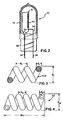
- FIGURE 2 there is illustrated an example of an incandescent lamp 30, in this particular embodiment being of the tungsten halogen variety, which utilizes a compact filament configuration that reduces stray light in a reflector-type lamp.
- the filament wire utilized may be of the fine wire variety which is defined to be a filament wire having a diameter of about 0,11 mm (4.5 mils) or less.
- Lamp 30 has a tubular envelope 32 made of a suitable light transmissive material such as aluminosilicate glass.
- a pair of lead in wires 34 and 36, portions of which serve as mounting means, are press sealed in envelope 32 at press seal 38.
- Lead in wires 34 and 36 can be formed from molybdenum, which will form a relatively strain free hermetic seal with glass envelope 32.
- a refractory metal (such as tungsten) coiled coil filament 40 with legs 41, is disposed within envelope 32 and is attached to the internal ends of lead in wires 34 and 36.
- envelope 32 is filled with a fill gas comprising an inert gas and a halogen or halide.
- a fill gas comprising an inert gas and a halogen or halide.
- Suitable examples of such an inert gas include argon or krypton or xenon and nitrogen.
- the halogen or halide additive which is in its gaseous state under the heat of lamp operation or may be incorporated as part of the gaseous compound, functions to reduce the coloration of the lamp envelope.
- FIGURES 3 and 4 illustrate enlarged views of tungsten filament 40 and its coiled coil stages, respectively. Each stage has pitch or percent pitch, which is equal to S, the center to center spacing of the turns, divided by d the diameter of the wire or coil, multiplied by 100.
- FIGURE 3 illustrates the primary pitch of filament 40A having center to center spacing of S1, wire diameter d1 and outer diameter D1.
- S2 is the center to center spacing of the coiled coil filament
- BL is the body length of the coiled coil filament.
- the secondary pitch of the filament is in the range of about 1.40 to about 1.60.
- the primary winding diameter is equal to D1
- the secondary winding diameter is equal to D2.
- the method further includes the step of removing substantially all of the core of coiled coil filament 40, except for removing the core in legs 41 of filament 40.
- the core in legs 41 is preferably left intact in order to preserve the structural integrity of filament 40 when the filament is mounted within the envelope, by being crimped or attached by the legs to the mounting means, in forming light source 16.
- Light source 16 is then disposed within the central angular region of reflector 12.
- FIGURE 7 illustrates outer diameter D2 of the filament winding illustrated in FIGURE 6, wherein the primary mandrel diameter M1 is greater than the diameter of filament wire 39 and the secondary mandrel diameter M2 is greater than the diameter of primary coil 40A.
- the 105 watt/245 volt lamp it is noted, first of all, that such a lamp will utilize an extremely long wire of thin diameter, as exhibited by the high value obtained from the ratio of length to wire diameter (L/d)), therefore, optimum winding of such a wire will be extremely important in such a lamp.
- the resulting body length (BL) to outer diameter (D2) ratio is about 65:1; this results in a long flimsy filament which will ultimately require at least one or more additional filament supports to support such a filament within a small incandescent lamp envelope.
- the improved winding utilizes larger mandrel ratios, particularly a secondary mandrel ratio that is larger than a primary mandrel ratio, which results in a body length to outer diameter ratio of about 37:1.
- the improved filament design is much more compact and, depending on the type of mounting scheme, probably would require no extra filament supports or at least less supports than in the sample winding.
- the 35 watt/84 volt filament example similar results are exhibited in that in the improved winding there is a reduction in the body length to outer diameter ratio which creates a more compact filament design.
- compacting is achieved by greater mandrel ratios and the upper limit in the mandrel ratio values is determined by the body length (BL) of the ultimate filament design being greater than or equal to the outer diameter (D2) of the resulting filament.
- the test was conducted with two hardglass halogen (HGH) capsules having wattages close to 45 watts and operating at a voltage of about 84 volts but having filaments of different lengths.
- a 1,14 cm (0.45 inch) focal length, continuous contour (no rear cup recess), aluminum, parabolic reflector was used with a PAR 38 flood lens having the center filled with a continuous pattern.
- the candlepower versus angle from center of the two lamps are shown as A and B in FIGURE 8.
- Curve A 45 watt
- Curve B Curve A (45 watt) is normalized as A′ (dotted line) to adjust it down to the capsule lumens of the longer filament (46.6 watts), Curve B.
- the longer filament gave a minimum beam size of 40° while the shorter filament gave a minimum beam size of 27° degrees. These were the relatively sharp visual edges when adjusted to minimum beam size.
- the longer filament produces more spread into the tails of the pattern and consequently has a lower efficiency of utilization, 62% compared to 67% for the shorter filament. This illustrates the advantage of improved collection for the shorter, more compact filament design of the light source.
- the aforementioned example illustrates that in designing filament configurations for reflector-type lamp applications it is preferable to utilize a filament design that evenly spreads out the light energy throughout the central angular region, while maintaining a reasonable amount of compactness, in order to simplify the task of shaping the light emitted from the lamp with an appropriate lens.
- a long filament (low mandrel ratios) on the other hand spreads the light out too much, beyond the desired central region, such that portions of the reflector will be hit which will greatly disperse the light, making it much more difficult to shape the beam with a lens.
- a filament design that has a small diameter also tends to have a hot spot in the middle which creates a bright spot in the middle of the filament that makes it difficult to dispense the light effectively with a lens.
- Elimination of the rectifying means is particularly important in the 225 to 245 volt range since the small filament mass leads to greater thermal fluctuations and useful where small reflector lamp designs are sought due to the heat generated by the lamp capsule that the rectifier is exposed to.
- filament sag was reduced and compactness achieved by lowering the voltage requirement of the lamp so that a shorter, larger diameter filament wire could be used.
- the shorter, thicker wire has allowed for an increase in the mandrel ratios in order to achieve compactness, however transformers were now necessary to lower the line voltage.
- the teachings of the present invention has provided the ability to design compact high voltage filaments that lead to a simplification in reflector lamp fixture design and ultimately lower costs due to the elimination of a transformer (or voltage reducing means) in some fixtures.
- the more compact filament design of the present invention will also lead to an increase in structural rigidity and allows for smaller capsule design (and possibly smaller reflector lamps) for high pressure tungsten halogen lamps of various wattage and voltage values that lead to lower capsule energy and improved containment due to possible lamp failures during lamp arc out. This leads to lower material costs for glass, fill gas, etc.
- the filament design and method for making such of the present invention is applicable to lower wattage lamps utilizing a hard glass envelope and may be applied to high wattage lamps utilizing high temperature materials for the envelope such as quartz.
Landscapes
- Non-Portable Lighting Devices Or Systems Thereof (AREA)
Claims (14)
- Lampe vom Reflektortyp mit verringertem Fokalverlust mit einem Reflektor (12), der einen winkelförmigen Zentralbereich und eine Lichtquelle (16) aufweist, die innerhalb des Reflektors (12) angeordnet ist, wobei die Lichtquelle (16) umfaßt:
Eine hermetisch abgedichtete, lichtdurchlässige Hülle (32); Elemente (34, 36) zur strukturellen und elektrischen Montage eines Glühfadens (40) innerhalb der Hülle (32); und
einen Doppelwendel-Glühfaden (40) aus hitzebeständigem Metall, der mit den genannten Montageelementen (34,36) elektrisch verbunden und von denselben gehalten ist, wobei der primäre Wicklungsdurchmesser D₁ und der sekundäre Wicklungsdurchmesser D₂ des Glühfadens (14) dargestellt sind durch: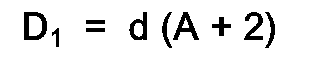

d = dem Drahtdurchmesser des Glühfadens

derart, daß die Kompaktheit des Glühfadens (40) für einen verringerten Fokalverlust und für eine verbesserte Reflektorsammeleffizienz sorgt, da das Licht von dem Glühfaden in den winkelförmigen Zentralbereich des Reflektors (12) hinein kanalisiert wird. - Lampe nach Anspruch 1, dadurch gekennzeichnet, daß der Glühfaden (40) ein primäres Pitchverhältnis und ein sekundäres Pitchverhältnis aufweist, die etwa 1,70 nicht überschreiten.
- Lampe nach Anspruch 2, dadurch gekennzeichnet, daß der sekundäre Pitch des Glühfadens (40) sich im Bereich von etwa 1,40 bis etwa 1,60 befindet.
- Lampe nach Anspruch 1, 2 oder 3, dadurch gekennzeichnet, daß die Elemente zur Halterung des Glühfadens der Lichtquelle aus zumindest zwei Leitungsdrähten (34,36) bestehen.
- Lampe nach einem der vorhergehenden Ansprüche, dadurch gekennzeichnet, daß der Drahtdurchmesser (d) des doppelt gewendelten Glühfadens etwa 0,114 mm (4,5 mils) oder weniger beträgt.
- Lampe nach einem der vorhergehenden Ansprüche, dadurch gekennzeichnet, daß die Hülle (32) der Lichtquelle (16) ein Füllgas einschließt, das ein Halogen oder ein Halogenid als Teil desselben enthält.
- Lampe nach einem der vorhergehenden Ansprüche, dadurch gekennzeichnet, daß die Elemente (34,36) für die Montage des Glühfadens (40) ein Paar Zuleitungsdrähte (34,36) umfassen, die in die Hülle (32) durch Quetschung eingesiegelt sind und sich von derselben wegerstrecken.
- Lampe nach ieinem der vorhergehenden Ansprüche, dadurch gekennzeichnet, daß der Glühfaden (40) im wesentlichen kernlos ist, mit Ausnahme der Anschlußenden (41) des Glühfadens (40).
- Lampe nach einem der vorhergehenden Ansprüche, dadurch gekennzeichnet, daß die Hülle (32) der Lichtquelle eine Infrarot reflektierende Schicht aufweist, derart, daß infrarotes Licht auf den Glühfaden (40) zurückreflektiert wird.
- Lampe nach einem der vorhergehenden Ansprüche, dadurch gekennzeichnet, daß der Reflektor (12) ein aluminisierter parabolischer Reflektor ist.
- Lampe nach einem der Ansprüche 1 bis 9, dadurch gekennzeichnet, daß der Reflektor (12) ein elliptischer Reflektor ist.
- Lampe nach einem der vorhergehenden Ansprüche, dadurch gekennzeichnet, daß der Reflektor (12) eine dichroische Beschichtung aufweist.
- Lampe nach einem der vorhergehenden Ansprüche, dadurch gekennzeichnet, daß der Reflektor (12) eine metallische Beschichtung aufweist, wobei das Metall aus der aus Aluminium und Silber bestehenden Gruppe ausgewählt ist.
- Verfahren zur Verringerung des Fokalverlusts und Vergrößerung der Effizienz der Sammlung durch den Reflektor bei einer Lampe vom Reflektortyp, bei welcher die Lampe einen Reflektor (12), eine innerhalb des Reflektors (12) angeordnete Lichtquelle (16) und eine dem Reflektor (12) benachbarte Linse (14) aufweist, wobei dieses Verfahren aus den folgenden Schritten besteht:
Zurverfügungstellen einer Litze aus faserigem Glühfadendraht (39) mit einer besonderen Länge L und einem Durchmesser d für eine spezielle Wattleistung, Spannung und Leistungsfähigkeit;
Wickeln dieses Glühfadendrahtes (39) um einen primären Dorn (50) mit einem Durchmesser M₁, der durch M₁ = A(d) bestimmt ist, um eine primäre Wendel (40A) zu erzeugen, bei welcher 1,70 ≦ A ≦ 4,00 ist;
Wickeln der primären Wendel (40A) um einen sekundären Dorn (60) mit einem sekundären Dorndurchmesser M₂, der durch M₂ = B(M₁ + 2d) bestimmt ist, um eine Doppelwendel zu erzeugen, bei welcher B ≧ A und der Durchmesser (D₂) dieser Doppelwendel (40) kleiner ist als ihre Länge (BL);
Entfernen im wesentlichen des gesamten Kerns des Doppelwendel-Glühfadens (40);
axiale Montage des Glühfadens (40) innerhalb der Längsachse einer Hülle (32), um die Lichtquelle (16) zu bilden; und
Anordnen dieser Lichtquelle (16) innerhalb des zentralen Winkelbereichs des Reflektors (12).
Applications Claiming Priority (2)
| Application Number | Priority Date | Filing Date | Title |
|---|---|---|---|
| US06/852,002 US4686412A (en) | 1986-04-14 | 1986-04-14 | Reflector-type lamp having reduced focus loss |
| US852002 | 1986-04-14 |
Publications (3)
| Publication Number | Publication Date |
|---|---|
| EP0241911A2 EP0241911A2 (de) | 1987-10-21 |
| EP0241911A3 EP0241911A3 (en) | 1989-10-11 |
| EP0241911B1 true EP0241911B1 (de) | 1994-10-26 |
Family
ID=25312255
Family Applications (1)
| Application Number | Title | Priority Date | Filing Date |
|---|---|---|---|
| EP87105510A Expired - Lifetime EP0241911B1 (de) | 1986-04-14 | 1987-04-14 | Lampe vom Reflektortyp mit verringertem Fokalverlust |
Country Status (6)
| Country | Link |
|---|---|
| US (1) | US4686412A (de) |
| EP (1) | EP0241911B1 (de) |
| JP (1) | JPS62252062A (de) |
| AU (1) | AU583240B2 (de) |
| CA (1) | CA1280148C (de) |
| DE (1) | DE3750683T2 (de) |
Families Citing this family (22)
| Publication number | Priority date | Publication date | Assignee | Title |
|---|---|---|---|---|
| US4683397A (en) * | 1986-04-14 | 1987-07-28 | Gte Products Corporation | Compact incandescent coiled coil filament |
| EP0271857B1 (de) * | 1986-12-16 | 1997-04-02 | Gte Products Corporation | Kompakte Doppelglühwendel mit Haltern |
| US4835443A (en) * | 1986-12-16 | 1989-05-30 | Gte Products Corporation | High voltage hard glass halogen capsule |
| EP0271859B1 (de) * | 1986-12-16 | 1997-04-02 | Gte Products Corporation | Kompakte Doppelglühwendel mit Anwendung der Steigung für Biegungskontrolle |
| DE3824904A1 (de) * | 1988-07-22 | 1990-01-25 | Philips Patentverwaltung | Schaltungsanordnung zum betrieb einer elektrischen gluehlampe aus einer wechselspannungsquelle und gluehlampe zum betrieb in einer solchen schaltungsanordnung |
| USD321762S (en) | 1989-02-17 | 1991-11-19 | North American Philips Corporation | Reflector spot lamp |
| US5187405A (en) * | 1991-02-21 | 1993-02-16 | General Electric Company | Double filament incandescent lamp |
| US5272408A (en) * | 1991-05-09 | 1993-12-21 | Gte Products Corporation | Lamp and reflector assembly |
| DE4343989C2 (de) * | 1993-12-22 | 2002-12-19 | Patent Treuhand Ges Fuer Elektrische Gluehlampen Mbh | Halogenglühlampe |
| JP3379613B2 (ja) * | 1994-06-30 | 2003-02-24 | 東芝ライテック株式会社 | 蛍光ランプ装置および照明装置 |
| US5720548A (en) * | 1995-11-14 | 1998-02-24 | Progressive Technology In Lighting, Inc. | High luminance fluorescent lamp assembly |
| JP2001345077A (ja) * | 2000-03-30 | 2001-12-14 | Toshiba Lighting & Technology Corp | ハロゲン電球および照明装置 |
| US6637912B2 (en) * | 2000-10-20 | 2003-10-28 | Acuity Brands, Inc. | Luminaire lens |
| JP4470084B2 (ja) * | 2001-03-06 | 2010-06-02 | 河北ライティングソリューションズ株式会社 | 電球 |
| US6726345B2 (en) * | 2001-09-21 | 2004-04-27 | Acuity Brands, Inc. | Luminaire lens |
| EP1697963A2 (de) * | 2003-12-16 | 2006-09-06 | Koninklijke Philips Electronics N.V. | Elektrische leuchtlampe und herstellungsverfahren dafür |
| US7977855B2 (en) * | 2005-12-22 | 2011-07-12 | Randal Lee Wimberly | Incandescent lamp and illumination system with optimized filament shape and size |
| US7541726B2 (en) * | 2006-05-17 | 2009-06-02 | Osram Sylvania Inc. | Lamp filament |
| DE102008059292A1 (de) * | 2008-11-27 | 2010-06-02 | Osram Gesellschaft mit beschränkter Haftung | Glühlampe |
| JP5586685B2 (ja) * | 2009-04-03 | 2014-09-10 | アプライド マテリアルズ インコーポレイテッド | 内部フューズシステムを具備したランプ |
| WO2014150071A1 (en) | 2013-03-15 | 2014-09-25 | Applied Materials, Inc. | Tubular light source having overwind |
| USD757305S1 (en) * | 2015-02-27 | 2016-05-24 | Osram Sylvania Inc. | Lamp capsule with coating |
Family Cites Families (12)
| Publication number | Priority date | Publication date | Assignee | Title |
|---|---|---|---|---|
| US2218345A (en) * | 1935-04-10 | 1940-10-15 | Spaeth Charles | Incandescent lamp |
| US2424518A (en) * | 1944-12-04 | 1947-07-22 | Gen Electric | Coil electrode |
| DE1472521A1 (de) * | 1965-11-16 | 1969-01-30 | Medicor Muevek | Lampe mit gerichtetem Licht,insbesondere Scheinwerfer |
| US3383539A (en) * | 1967-02-06 | 1968-05-14 | Sylvania Electric Prod | Projection lamp |
| NL7302046A (de) * | 1973-02-14 | 1974-08-16 | ||
| US4208609A (en) * | 1978-09-25 | 1980-06-17 | General Electric Company | Squirm resistant filament |
| US4316116A (en) * | 1979-12-19 | 1982-02-16 | General Electric Company | Triple-coil incandescent filament |
| US4461973A (en) * | 1982-03-19 | 1984-07-24 | Duro-Test Corporation | Energy-efficient incandescent lamp with improved filament characteristics |
| US4480212A (en) * | 1982-06-14 | 1984-10-30 | Diolight Technology, Inc. | Extended life incandescent lamp with self contained diode and reflector |
| US4499401A (en) * | 1983-03-03 | 1985-02-12 | General Electric Company | Triple coil incandescent filament |
| US4547704A (en) * | 1983-08-01 | 1985-10-15 | General Electric Company | Higher efficiency incandescent lighting units |
| US4683397A (en) * | 1986-04-14 | 1987-07-28 | Gte Products Corporation | Compact incandescent coiled coil filament |
-
1986
- 1986-04-14 US US06/852,002 patent/US4686412A/en not_active Expired - Fee Related
-
1987
- 1987-04-09 CA CA000534317A patent/CA1280148C/en not_active Expired - Lifetime
- 1987-04-13 AU AU71475/87A patent/AU583240B2/en not_active Ceased
- 1987-04-14 DE DE3750683T patent/DE3750683T2/de not_active Expired - Fee Related
- 1987-04-14 EP EP87105510A patent/EP0241911B1/de not_active Expired - Lifetime
- 1987-04-14 JP JP62089973A patent/JPS62252062A/ja active Pending
Also Published As
| Publication number | Publication date |
|---|---|
| DE3750683D1 (de) | 1994-12-01 |
| AU583240B2 (en) | 1989-04-20 |
| US4686412A (en) | 1987-08-11 |
| EP0241911A2 (de) | 1987-10-21 |
| DE3750683T2 (de) | 1995-07-20 |
| CA1280148C (en) | 1991-02-12 |
| AU7147587A (en) | 1987-10-15 |
| EP0241911A3 (en) | 1989-10-11 |
| JPS62252062A (ja) | 1987-11-02 |
Similar Documents
| Publication | Publication Date | Title |
|---|---|---|
| EP0241911B1 (de) | Lampe vom Reflektortyp mit verringertem Fokalverlust | |
| CN1115711C (zh) | 具有螺旋形灯泡的紧凑型荧光灯 | |
| US5556191A (en) | Electric reflector lamp | |
| JPH10501368A (ja) | 白熱電球及び白熱電球用発光体 | |
| JPH0367456A (ja) | 白熱ランプ用のフィラメント心合わせ支持体 | |
| US5789847A (en) | High efficiency sealed beam reflector lamp with reflective surface of heat treated silver | |
| US4536834A (en) | R lamp having an improved neck section for increasing the useful light output | |
| US4918354A (en) | Compact coiled coil incandescent filament with supports and pitch control | |
| EP0735571B1 (de) | Glühlampe | |
| US4683397A (en) | Compact incandescent coiled coil filament | |
| US6087775A (en) | Exterior shroud lamp | |
| KR100420874B1 (ko) | 반사코팅된백열전등 | |
| EP0271857B1 (de) | Kompakte Doppelglühwendel mit Haltern | |
| US6225731B1 (en) | Glass halogen lamp with internal ellipsoidal shroud | |
| US2901648A (en) | Reflector mercury lamp | |
| JP4229985B2 (ja) | 反射膜を備えた電球 | |
| CA2311941A1 (en) | Electrical incandescent lamp having an ir-reflective coating | |
| US4835443A (en) | High voltage hard glass halogen capsule | |
| EP0271859B1 (de) | Kompakte Doppelglühwendel mit Anwendung der Steigung für Biegungskontrolle | |
| EP0271858B1 (de) | Halogenkolben aus Hartglas für Hochspannung | |
| US20020067109A1 (en) | Garage lamp | |
| CN101110344A (zh) | 具有红外反射涂层的电灯 | |
| CA2249720C (en) | Incandescent lamp with reflection coating | |
| JPS63292561A (ja) | 無電極放電灯装置 | |
| JPH0464141B2 (de) |
Legal Events
| Date | Code | Title | Description |
|---|---|---|---|
| PUAI | Public reference made under article 153(3) epc to a published international application that has entered the european phase |
Free format text: ORIGINAL CODE: 0009012 |
|
| 17P | Request for examination filed |
Effective date: 19870414 |
|
| AK | Designated contracting states |
Kind code of ref document: A2 Designated state(s): BE DE FR GB NL |
|
| PUAL | Search report despatched |
Free format text: ORIGINAL CODE: 0009013 |
|
| AK | Designated contracting states |
Kind code of ref document: A3 Designated state(s): BE DE FR GB NL |
|
| 17Q | First examination report despatched |
Effective date: 19910717 |
|
| GRAA | (expected) grant |
Free format text: ORIGINAL CODE: 0009210 |
|
| AK | Designated contracting states |
Kind code of ref document: B1 Designated state(s): BE DE FR GB NL |
|
| REF | Corresponds to: |
Ref document number: 3750683 Country of ref document: DE Date of ref document: 19941201 |
|
| ET | Fr: translation filed | ||
| NLT1 | Nl: modifications of names registered in virtue of documents presented to the patent office pursuant to art. 16 a, paragraph 1 |
Owner name: OSRAM SYLVANIA INC. TE DANVERS, MASSACHUSETTS, VER |
|
| PLBE | No opposition filed within time limit |
Free format text: ORIGINAL CODE: 0009261 |
|
| STAA | Information on the status of an ep patent application or granted ep patent |
Free format text: STATUS: NO OPPOSITION FILED WITHIN TIME LIMIT |
|
| 26N | No opposition filed | ||
| REG | Reference to a national code |
Ref country code: GB Ref legal event code: 732E |
|
| REG | Reference to a national code |
Ref country code: GB Ref legal event code: IF02 |
|
| PGFP | Annual fee paid to national office [announced via postgrant information from national office to epo] |
Ref country code: GB Payment date: 20030422 Year of fee payment: 17 |
|
| PGFP | Annual fee paid to national office [announced via postgrant information from national office to epo] |
Ref country code: BE Payment date: 20030425 Year of fee payment: 17 |
|
| PGFP | Annual fee paid to national office [announced via postgrant information from national office to epo] |
Ref country code: NL Payment date: 20030430 Year of fee payment: 17 Ref country code: FR Payment date: 20030430 Year of fee payment: 17 |
|
| PGFP | Annual fee paid to national office [announced via postgrant information from national office to epo] |
Ref country code: DE Payment date: 20030627 Year of fee payment: 17 |
|
| PG25 | Lapsed in a contracting state [announced via postgrant information from national office to epo] |
Ref country code: GB Free format text: LAPSE BECAUSE OF NON-PAYMENT OF DUE FEES Effective date: 20040414 |
|
| PG25 | Lapsed in a contracting state [announced via postgrant information from national office to epo] |
Ref country code: BE Free format text: LAPSE BECAUSE OF NON-PAYMENT OF DUE FEES Effective date: 20040430 |
|
| BERE | Be: lapsed |
Owner name: *GTE PRODUCTS CORP. Effective date: 20040430 |
|
| PG25 | Lapsed in a contracting state [announced via postgrant information from national office to epo] |
Ref country code: NL Free format text: LAPSE BECAUSE OF NON-PAYMENT OF DUE FEES Effective date: 20041101 |
|
| PG25 | Lapsed in a contracting state [announced via postgrant information from national office to epo] |
Ref country code: DE Free format text: LAPSE BECAUSE OF NON-PAYMENT OF DUE FEES Effective date: 20041103 |
|
| GBPC | Gb: european patent ceased through non-payment of renewal fee |
Effective date: 20040414 |
|
| PG25 | Lapsed in a contracting state [announced via postgrant information from national office to epo] |
Ref country code: FR Free format text: LAPSE BECAUSE OF NON-PAYMENT OF DUE FEES Effective date: 20041231 |
|
| NLV4 | Nl: lapsed or anulled due to non-payment of the annual fee |
Effective date: 20041101 |
|
| REG | Reference to a national code |
Ref country code: FR Ref legal event code: ST |