EP0241899A2 - Support d'attelage de semi-remorque pour wagon ferroviaire - Google Patents
Support d'attelage de semi-remorque pour wagon ferroviaire Download PDFInfo
- Publication number
- EP0241899A2 EP0241899A2 EP87105473A EP87105473A EP0241899A2 EP 0241899 A2 EP0241899 A2 EP 0241899A2 EP 87105473 A EP87105473 A EP 87105473A EP 87105473 A EP87105473 A EP 87105473A EP 0241899 A2 EP0241899 A2 EP 0241899A2
- Authority
- EP
- European Patent Office
- Prior art keywords
- stanchion
- strut
- mating
- motive
- wheels
- Prior art date
- Legal status (The legal status is an assumption and is not a legal conclusion. Google has not performed a legal analysis and makes no representation as to the accuracy of the status listed.)
- Withdrawn
Links
Images
Classifications
-
- B—PERFORMING OPERATIONS; TRANSPORTING
- B61—RAILWAYS
- B61D—BODY DETAILS OR KINDS OF RAILWAY VEHICLES
- B61D45/00—Means or devices for securing or supporting the cargo, including protection against shocks
- B61D45/001—Devices for fixing to walls or floors
- B61D45/004—Fixing semi-trailers
- B61D45/005—Fixing semi-trailers by using fifth wheel locks
Definitions
- the present invention relates generally to supports for trailers on railroad cars and more specifically to an improved stanchion to support trailers on a railroad car.
- Another object of the present invention is to provide a collapsible stanchion for a flat bed which is adjustable along the length of the railroad car.
- Still another object of the present invention is to provide a self-propelled stanchion which can be moved longitudinally as well as raised and lowered.
- a stanchion with first and second struts pivotally connected to a king pin mating element at one end and wheels at the other end of the struts.
- a motive assembly interconnects at the wheel ends of the first and second struts and move them relative to each other to raise and lower the mating element.
- a propulsion system is provided to move the stanchion on the surface of a railroad car.
- a longitudinal channel is provided in the surface of the railroad car in which the wheels move.
- the motive assembly includes a threaded member and a screw which are rotated relative to each other so as to move the wheeled ends relative to each other.
- a single electrical motor includes a pair of clutches to interconnect the motor to the motive assembly and the propulsion system and are individually controlled to either propel or raise and lower the stanchion.
- a rack is provided in the channel and a pinion is provided on wheeled ends of the struts to propel the strut along the surface of the car.
- the transmission or clutches are braking clutches which lock the propulsion system or the motive assembly when deactivated. Electrical energy mounted in the car is connected to a conductor strip in the channel and provides the power to the electric motor.
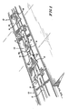
- a plurality of railroad cars 10 are shown in Figure 1 at a siding ready for loading of tractor trailers.
- a channel 12 runs along the longitudinal axis of the railroad cars in the deck 14.
- Two oppositely facing stanchions 16 are provided on each car.
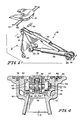
- the stanchion 16 includes a fifth wheel plate structure 18.
- a pair of struts 20 and 22 are pivotally connected by pin 24 to the fifth wheel plate structure 18.
- a pair of wheels 26 and a pair of pinions 28 are provided at the other end of strut 20 and a pair of wheels 30 are provided at the other end of strut 22.
- a pair of flanges or plate 32 extend laterally from the strut 22 and have wheels 34 at the ends thereof.
- the pinions 28 cooperate with the rack in channel 12 to move the stanchions along the length of the railroad cars. This allows maximum flexibility of placement as well as the ability to place the trailers close as possible to each other.
- the wheeled ends of struts 20 and 22 are interconnected by telescopic elements 36 and 38. The extension and contraction of the telescopic elements 36 and 38 causes the stanchion to rise and fall respectively. As illustrated in Figure 1, the stanchions are in their lowermost position allowing trucks, trailers and other elements to be driven thereover.
- wheels 26, 30 and 34 are shown, other friction reducing mechanism like sliders may be used but are not preferred.
- Electric motor 40 for example a DC motor
- An electric clutch 42 interconnects the motor 40 and a screw 44.
- a threaded element 46 is mounted to the end of telescopic element 36. As the motor turns screw 44, the threaded element 46 and telescopic element 36 are moved relative to telescopic element 38.
- a second electrical control clutch 48 connects the motor 40 to planetary reducer 50, gear train 52, worm gear 54 and gear 56 to drive pinion 28.
- the clutches are brake clutches, namely, they prevent rotation of the output structure when disengaged. This, along with the fact that both the elevating screw and the drive worm are self locking, will maintain the stanchion in the raised position so as to support the load as well as using the pinions to lock the stanchion in place on the surface of the railroad car.
- channel 12 is illustrated specifically in Figure 4 as being formed from a pair of castings or extrusions 60 interconnected by welded ribs 61.
- a pair of rails 62 and 64 lie within the extrusions 60 and are secured thereto by fastener 66.
- Each rail 62, 64 includes a race 67 to receive the wheels 26 and 30 of the stanchion.
- Extending between the opposed rails 62 and 64 are a plurality of spaced pins 68 which form in total a rack to cooperate with pinion 218 to form a rack and pinion drive.
- a power rail 70 lies in the face of rail 64 and is separated therefrom by an insulator 72.
- the power rail runs the extent of the channel and is connected to a source of electrical power either on the car or provided to the car through the train system.
- a power pickup 74 extends from the wheel 26 and is connected to the motor 40 and the control circuit for the motor.
- the power rail is preferably made of stainless steel, the power pickup 74 is preferably made of German silver and is spring loaded so it contact with the power rail 70. In operation, current would flow from the source through the power rail and pickup, then through appropriate control circuits to ground and through the motor to ground in parallel with the control circuits.
- a control bar 80 and king pin lock rod 82 are illustrated in Figures 1 and 2 as being connected to the fifth wheel plate structure 18.
- the control bar 80 is a four positioned joy stick which allows raising and lowering as well as forward and reverse movement of the stanchion.
- electric clutch 40 or 48 will be activated and the motor 40 will be driven in the forward or reverse direction.
- the train is ready for loading as illustrated in Figure 1 with the stanchions 16 collapsed onto the deck.
- the driver drives the trailer onto a car 10 and parks it thereon.
- the landing gear is dropped and the tractor is removed.
- the powered stanchion nearest to the king pin of the trailer will be partially raised as illustrated in Figure 5 by using the control bar 18.
- the stanchions 16 is then moved towards the trailer and engaging and locking the king pin.
- the stanchion is further raised to its uppermost position to raise the trailer and its landing gear clear of the deck.
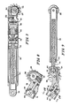
- FIG. 6 Another embodiment of the stanchion is illustrated in Figures 6-9. All the elements which operate in a similar manner to the previous embodiment include the same numbers.
- the pair of struts 20 and 22 are pivotably connected to the fifth wheel plate structure 18.
- a pair of wheels 26 provided at the other end of strut 20 and a pair of pinions 28 and a pair of wheels 30 are provided at the other end of strut 22.
- the wheeled end of struts 20, 22 are interconnected by telescopic elements 36 and 38.
- the extension and contraction of telescopic elements 36 and 38 cause the stanchion to fall and rise respectfully.
- the distance between the wheels 26 and 30 is shorter than the distance between the wheels 26 and 30 in Figure 2 in the rise position. This allows the oppositely facing stanchions in a common car to be placed closer together and thus increase the packing and reduce the aerodynamic drag.
- the power system for the stanchion of Figure 6 includes the screw 44 in element 38 and received in a thread element 46 in the telescopic element 36 a shown in Figure 9.
- a gear 82 is provided on the end of the screw 44 and is connected by a smaller gear 84 to an input 86 external the element 38.
- An external source of rotation for example an electric drill or a mechanical system, is connected via input 86 to drive the screw 44 through gears 82 and 84. If an electric drill is used, the gear 84 is smaller than the gear 82 to provide a reduction.
- the pinions 28 are connected to a gear 56 and worm gear 54 as shown in Figure 8.
- An external input 88 is provided to worm gear 54. As with the input 86, a source of rotations is received via input 88.
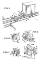
- a reaction collar 87 and 89 are provided about inputs 86 and 87 respectively.
- the reaction motion collars 87 and 89 include a rectangular shoulder 90 and 91 respectively. This is shown specifically for input 86 and reaction collar 87 in Figure 10.
- An external power source having a housing 92 with external rectangular surfaces 94 and control drive shaft 96 mates with the input 86 and reaction collar 87 as shown in Figure 11.
- the drive shaft 96 includes a socket 98 to receive input 86.
- the faces 94 of the power source housing 92 mate with shoulders 90 of the reaction collar 87. This permits the reaction torque of the power source to be absorbed by the car, rather than through the body of the human operator. This increases operator safety and permits the use of higher torque than an operator could withstand without torque transmission to the car.
- this configuration of the stanchion also increases the reliability since there are a fewer parts to be maintained.
- the operation of the stanchion of Figure 6 is the same as that described from the previous embodiment, except that the control bar 80 is not provided and the raising or lowering and horizontal movement of the stanchion is produced by connecting the external source of rotation to the individual inputs 86 and 88.
Landscapes
- Engineering & Computer Science (AREA)
- Transportation (AREA)
- Mechanical Engineering (AREA)
- Vehicle Cleaning, Maintenance, Repair, Refitting, And Outriggers (AREA)
- Bridges Or Land Bridges (AREA)
Applications Claiming Priority (2)
| Application Number | Priority Date | Filing Date | Title |
|---|---|---|---|
| US06/853,561 US4718800A (en) | 1986-04-18 | 1986-04-18 | Stanchion |
| US853561 | 1986-04-18 |
Publications (2)
| Publication Number | Publication Date |
|---|---|
| EP0241899A2 true EP0241899A2 (fr) | 1987-10-21 |
| EP0241899A3 EP0241899A3 (fr) | 1988-10-12 |
Family
ID=25316356
Family Applications (1)
| Application Number | Title | Priority Date | Filing Date |
|---|---|---|---|
| EP87105473A Withdrawn EP0241899A3 (fr) | 1986-04-18 | 1987-04-13 | Support d'attelage de semi-remorque pour wagon ferroviaire |
Country Status (4)
| Country | Link |
|---|---|
| US (1) | US4718800A (fr) |
| EP (1) | EP0241899A3 (fr) |
| AU (1) | AU7105987A (fr) |
| ZA (1) | ZA872090B (fr) |
Cited By (3)
| Publication number | Priority date | Publication date | Assignee | Title |
|---|---|---|---|---|
| WO1992004219A1 (fr) * | 1990-09-12 | 1992-03-19 | Knorr Brake Holding Corporation | Crochet d'attelage de levage coulissant a dispositif de blocage |
| DE19814929A1 (de) * | 1998-04-03 | 1999-10-07 | Jost Werke Ag | Hubvorrichtung für eine Sattelkupplung |
| US7439268B2 (en) | 2003-07-18 | 2008-10-21 | Idexx Laboratories | Compositions containing prodrugs of florfenicol and methods of use |
Families Citing this family (20)
| Publication number | Priority date | Publication date | Assignee | Title |
|---|---|---|---|---|
| DE3939384C2 (de) * | 1989-03-03 | 1997-01-09 | Ackermann Fruehauf | Straßen-Schienen-Transportsystem |
| FI109671B (fi) * | 1989-03-03 | 2002-09-30 | Europ De Semi Remorques Sers S | Tie-kisko-kuljetusjärjestelmä |
| DE4312558A1 (de) * | 1993-04-17 | 1994-10-20 | Karl Mueller Gmbh & Co Kg Fahr | Fahrzeug zum Transport von Rollbehältern |
| US5551815A (en) * | 1995-01-06 | 1996-09-03 | General Electic Company | Stanchion for supporting moving and loading/unloading highway semi-trailers on rail cars |
| US5868379A (en) * | 1996-01-25 | 1999-02-09 | Rite-Hite Holding Corporation | Safety stand for trailer loading |
| US6736071B2 (en) | 1998-02-23 | 2004-05-18 | Westinghouse Air Brake Technologies Corporation | Rail cars for intermodal train |
| US6718886B2 (en) | 1998-02-23 | 2004-04-13 | Westinghouse Air Brake Technologies Corporation | Ramp car |
| US6520472B1 (en) | 1999-01-22 | 2003-02-18 | Rite-Hite Holding Corporation | Container restraint for a parked swap body |
| US6491352B2 (en) | 1999-02-22 | 2002-12-10 | Westinghouse Air Brake Technologies Corporation | Spring applied parking brake for rail cars |
| US6647898B2 (en) | 2001-12-14 | 2003-11-18 | Westinghouse Air Brake Technologies Corporation | Spring assisted apparatus for ramp actuating mechanism and movable draft arm arrangement |
| US7802664B2 (en) * | 2005-11-02 | 2010-09-28 | Dura Global Technologies, Llc | Power strut assembly |
| US8006817B2 (en) * | 2005-11-02 | 2011-08-30 | Dura Global Technologies, Llc | Power strut assembly |
| US7914042B2 (en) * | 2008-05-13 | 2011-03-29 | Rite-Hite Holding Corporation | Support frame vehicle restraints |
| US8528929B2 (en) | 2010-01-21 | 2013-09-10 | Midwest Industrial Door, Inc. | Trailer docking repositionable support |
| CA3184390A1 (fr) | 2010-05-19 | 2011-11-24 | Stabilock, LLC | Stabilisateur de remorque |
| US10065689B2 (en) | 2012-12-14 | 2018-09-04 | Rite-Hite Holding Corporation | Portable trailer stands |
| US9676429B1 (en) * | 2013-09-24 | 2017-06-13 | Fountaine Fifth Wheel Company | Vertical coupling fifth wheel device and method of use |
| CA3223688A1 (fr) | 2014-07-01 | 2016-01-01 | Stabilock, LLC | Dispositif de stabilisation et de retenue de remorque |
| USD902793S1 (en) | 2018-04-06 | 2020-11-24 | Rite-Hite Holding Corporation | Trailer stand |
| EP4289639A3 (fr) | 2018-04-06 | 2024-03-13 | Rite-Hite Holding Corporation | Supports de remorque ergonomiques manoeuvrables |
Family Cites Families (15)
| Publication number | Priority date | Publication date | Assignee | Title |
|---|---|---|---|---|
| US3127142A (en) * | 1964-03-31 | Retractable stanchion | ||
| US1179475A (en) * | 1914-05-27 | 1916-04-18 | George Paul Thomas | Spacing-table mechanism. |
| US2845878A (en) * | 1953-08-17 | 1958-08-05 | Pullman Standard Car Mfg Co | Freight vehicle stand |
| US2903977A (en) * | 1953-11-09 | 1959-09-15 | Yale & Towne Mfg Co | Trailer spotting apparatus and tractor |
| US2846172A (en) * | 1954-07-29 | 1958-08-05 | Pullman Standard Car Mfg Co | Fifth-wheel stand for freight vehicles |
| NL206169A (fr) * | 1955-04-12 | |||
| US3180282A (en) * | 1958-01-23 | 1965-04-27 | Pullman Inc | Fifth wheel stand |
| US3202390A (en) * | 1959-03-09 | 1965-08-24 | Pullman Inc | Fifth wheel stand |
| US3016025A (en) * | 1959-06-12 | 1962-01-09 | Gen Am Transport | Freight transportation systems and methods |
| US3287038A (en) * | 1960-05-04 | 1966-11-22 | Pullman Inc | Fifth wheel plate for railroad car fifth wheel stands |
| US3239962A (en) * | 1962-03-29 | 1966-03-15 | Amt Corp | Remotely controlled electrically driven and steered toy vehicle |
| US3189307A (en) * | 1963-07-10 | 1965-06-15 | Pullman Inc | Collapsible fifth wheel stand assemblies |
| US3291074A (en) * | 1964-12-14 | 1966-12-13 | Bethlehem Steel Corp | Trailer hitch for flat cars |
| US3942398A (en) * | 1974-10-10 | 1976-03-09 | Nasa | Zero torque gear head wrench |
| US4191107A (en) * | 1978-10-02 | 1980-03-04 | Pullman Incorporated | Articulated railway car |
-
1986
- 1986-04-18 US US06/853,561 patent/US4718800A/en not_active Expired - Lifetime
-
1987
- 1987-03-23 ZA ZA872090A patent/ZA872090B/xx unknown
- 1987-04-03 AU AU71059/87A patent/AU7105987A/en not_active Abandoned
- 1987-04-13 EP EP87105473A patent/EP0241899A3/fr not_active Withdrawn
Cited By (6)
| Publication number | Priority date | Publication date | Assignee | Title |
|---|---|---|---|---|
| WO1992004219A1 (fr) * | 1990-09-12 | 1992-03-19 | Knorr Brake Holding Corporation | Crochet d'attelage de levage coulissant a dispositif de blocage |
| US5462394A (en) * | 1990-09-12 | 1995-10-31 | Knorr Brake Holding Corp. | Latchmaster sliding pull up hitch |
| US5518354A (en) * | 1990-09-12 | 1996-05-21 | New York Air Brake Corporation | Hook for actuating pull up hitch |
| DE19814929A1 (de) * | 1998-04-03 | 1999-10-07 | Jost Werke Ag | Hubvorrichtung für eine Sattelkupplung |
| DE19814929B4 (de) * | 1998-04-03 | 2009-04-09 | Jost-Werke Gmbh | Hubvorrichtung für eine Sattelkupplung |
| US7439268B2 (en) | 2003-07-18 | 2008-10-21 | Idexx Laboratories | Compositions containing prodrugs of florfenicol and methods of use |
Also Published As
| Publication number | Publication date |
|---|---|
| EP0241899A3 (fr) | 1988-10-12 |
| US4718800A (en) | 1988-01-12 |
| AU7105987A (en) | 1987-10-22 |
| ZA872090B (en) | 1987-09-14 |
Similar Documents
| Publication | Publication Date | Title |
|---|---|---|
| US4718800A (en) | Stanchion | |
| US8534694B2 (en) | Powered converter dolly and securing device | |
| US9126644B2 (en) | Powered converter dolly and securing device | |
| US4470746A (en) | Mobile and swivelling trailer plate, more particularly for transportation of various vehicles | |
| US4944522A (en) | Pin retractor for semi-trailer tandems | |
| US4730685A (en) | Apparatus for moving a multi-wheeled vehicle | |
| CA1182066A (fr) | Systeme de chargement a plaque tournante pour wagon | |
| CA2924653C (fr) | Chariot de convertisseur motorise et dispositif de fixation | |
| US5216956A (en) | Truck train system having a removable first truck and a second truck with a load platform and an extendable center sill | |
| US5853280A (en) | Semitrailer for vehicle transporation with removable upper platform | |
| EP0156842B1 (fr) | Appareil pour deplacer un vehicule a roues | |
| US6460468B1 (en) | Intermodal transport system | |
| US20080089766A1 (en) | Omni-Directional Towbarless Aircraft Transporter and Method for Moving Aircraft | |
| CZ173995A3 (en) | Transportation of cars in a closed multi-wheel trainler process and apparatus for making the same | |
| US9334003B2 (en) | Road trailer with orientable secondary wheelset | |
| US4111450A (en) | Multiple hook-up, movable axle trailer with removable track extensions, slidable kingpin, and pivotal axle assemblies | |
| DE60115581T2 (de) | Gabelhubwagen | |
| US3074569A (en) | Side-load and unload structure for railway-carried highway trailers | |
| US3360280A (en) | Horizontally and vertically movable fifth wheel for truck-tractors | |
| DE3523716A1 (de) | Hilfsgestell fuer den hilfstransport vom autoanhaenger bzw. lastkraftwagenanhaenger | |
| US2351829A (en) | Vehicle construction | |
| US3227294A (en) | Truck body transfer system | |
| DE19813440A1 (de) | Be- und Entladungssystem für Kraftfahrzeuge auf Bahnwagen | |
| US20100314180A1 (en) | Mobilizing apparatus for airplanes | |
| US5651656A (en) | Rail transportable ramps for loading semi-trailers on trains |
Legal Events
| Date | Code | Title | Description |
|---|---|---|---|
| PUAI | Public reference made under article 153(3) epc to a published international application that has entered the european phase |
Free format text: ORIGINAL CODE: 0009012 |
|
| AK | Designated contracting states |
Kind code of ref document: A2 Designated state(s): DE FR GB |
|
| RIN1 | Information on inventor provided before grant (corrected) |
Inventor name: ENGLE, THOMAS H. |
|
| PUAL | Search report despatched |
Free format text: ORIGINAL CODE: 0009013 |
|
| AK | Designated contracting states |
Kind code of ref document: A3 Designated state(s): DE FR GB |
|
| STAA | Information on the status of an ep patent application or granted ep patent |
Free format text: STATUS: THE APPLICATION IS DEEMED TO BE WITHDRAWN |
|
| 18D | Application deemed to be withdrawn |
Effective date: 19890413 |
|
| RIN1 | Information on inventor provided before grant (corrected) |
Inventor name: ENGLE, THOMAS H. |