EP0241789A2 - Appareil pour l'alimentation d'articles en forme de tige dans une trémie - Google Patents
Appareil pour l'alimentation d'articles en forme de tige dans une trémie Download PDFInfo
- Publication number
- EP0241789A2 EP0241789A2 EP87104599A EP87104599A EP0241789A2 EP 0241789 A2 EP0241789 A2 EP 0241789A2 EP 87104599 A EP87104599 A EP 87104599A EP 87104599 A EP87104599 A EP 87104599A EP 0241789 A2 EP0241789 A2 EP 0241789A2
- Authority
- EP
- European Patent Office
- Prior art keywords
- box
- hopper
- articles
- bar
- lids
- Prior art date
- Legal status (The legal status is an assumption and is not a legal conclusion. Google has not performed a legal analysis and makes no representation as to the accuracy of the status listed.)
- Granted
Links
Images


Classifications
-
- A—HUMAN NECESSITIES
- A24—TOBACCO; CIGARS; CIGARETTES; SIMULATED SMOKING DEVICES; SMOKERS' REQUISITES
- A24C—MACHINES FOR MAKING CIGARS OR CIGARETTES
- A24C5/00—Making cigarettes; Making tipping materials for, or attaching filters or mouthpieces to, cigars or cigarettes
- A24C5/35—Adaptations of conveying apparatus for transporting cigarettes from making machine to packaging machine
- A24C5/352—Adaptations of conveying apparatus for transporting cigarettes from making machine to packaging machine using containers, i.e. boats
- A24C5/356—Emptying the boats into the hopper of the packaging machine
Definitions
- This invention relates to an apparatus for supplying bar-like articles, more specifically bar-like articles such as cigarettes, filter plugs, etc, to a hopper.
- a plurality of plug supplying apparatus are provided below a hopper in which filter plugs are arranged in one direction and received in an accumulated fashion, and each of the plug supplying apparatus is connected to the cigarette producing machines.
- Filter plugs should desireably be received within the hopper so that the upper surfaces of the mass of plugs should be flat.
- the rate of consumption of the filter of the plugs by respective supplying apparatus is different or varied in dependence upon the producing speed or operating rate of respective cigarette producing machines, and therefore, the rate of consumption of filter plugs is not even throughout the mass so that the upper surface thereof becomes rugged and uneven.
- Filter plugs are normally supplied in quantity to the hopper in a generally rectangular parallelopiped box and they are arranged in parallel mass; the filter plugs are supplied into the hopper from the box by means of a supplying device constructed as described hereinafter.
- the supplying device is composed of a mounting frame that is reversible between up and down positions and on which said box is mounted, and there is a bottom lid that may be opened and closed to close the otherwise open bottom surface of the box.
- the box is mounted on the mounting frame when in the down position so that the open bottom surface of the box is directed upward, the open bottom surface of the box being closed by a bottom lid of the -supplying device.
- the box is reversed to move the said bottom lid adjacent the upper surface of the hopper, and then the bottom lid is pulled out and/or opened whereby the filter plugs fall from the box into the hopper.
- the aforesaid bottom lid is composed of a single plate, which is pulled out horizontally and therefore the stroke thereof becomes extremely great and the entire apparatus becomes large-scaled.
- the upper surface of the mass of filter plugs within the hopper is rugged and uneven due to the difference in consumption speeds as explained herein, some of the filter plugs falling from the box wall rolled slantwise from a raised portion of said surface toward a depressed portion which can cause a loss of attitude, thus posing inconveniences such that the filter plugs disturbed in attitude tend to foul the supply of the bar-like articles causing a loss of efficiency.
- the present invention seeks to overcome the above-described drawbacks as noted above, and an object of the invention is to provide a supplying apparatus which reduces the loss of attitude of bar-like articles to a minimum.
- a supplying apparatus for supplying bar-like articles to a hopper, comprising means for receiving a box containing said bar-like articles so that the box with its bottom open can be located above the hopper, a bottom lid closing said open bottom of the box preventing said bar-like articles from falling from the box into the hopper, characterised in that said bottom end is divided into a plurality of bottom lid sections each movably mounted and openable to allow the bar-like articles in said box above each lid to fall through the space created by the opening of each of said sections.
- apparatus for supplying bar-like articles to a hopper wherein, a box filled with bar-like parallel arranged articles is arranged on the hopper in a condition that the box is closed by a bottom lid preventing the articles from falling into the hopper, said bottom lid being divided into a plurality of small bottom lids, said small bottom lids being provided so that they may be rotated to create openings through which the articles can fall.
- supplying apparatus for supplying bar-like articles to a hopper wherein a box filled with bar-like parallel arranged articles is arranged on the hopper in a condition that the box is closed by a bottom lid, said bottom lid being divided into a plurality of small bottom lids, said small bottom lids being provided so that they may be rotated until an upper end of each of the small bottom lids fronts into said box, each of said small bottom lids being pivotally moved.
- the plurality of small bottom lids obtained by division of the bottom lid are respectively rotated about axes parallel to the bar-like articles to supply the bar-like articles through the openings left by rotating the small bottom lids. Therefore, the moving stroke to pivot the small bottom lids becomes extremely small as compared with prior art in which the bottom lid in the form of a single plate is moved in a horizontal direction of_ bar-like articles and is pulled out.
- the invention enables a miniaturization of the entire apparatus, and as bar-like articles will fall directly onto the depressed portion of the upper surface of the mass of bar-like articles within the hopper, whereby the upper surface of mass of bar-like articles within the hopper is maintained approximately flat, with the result that bar-like articles are not rolled slantwise from the raised portion toward the depressed portion of said surface and disturbance of attitude and the bar-like articles in avoided.
- a preferred feature of the invention provides an arrangement wherein each of the small bottom lids is oscillated when in the open position to distribute the bar-like articles within the box evenly, and therefore, bar-like articles may be supplied very quickly and orderly from the box toward the hopper so that there is enough time to insert the succeeding box and no delay in work occurs.
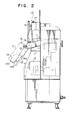
- a hopper is indicated at 1, a supplying device at 2, a controller at 3 and a supplying device at 10.
- the hopper 1 comprises, as shown in Fig. 3, two plates 1a disposed parallel to each other and spaced apart approximately equal to the length of filter plugs B in a lateral direction, and bottom plates 1b defining a V shape disposed therebelow, a plurality of supplying devices 2 being juxtaposed below the bottom plates 1b.
- Partition plates serve to define cavities leading to the respective supplying devices 2.
- Each bottom plate 1b consists of two small bottom plates which are superimposed, and where only two supplying apparatuses 2 are used, the small bottom plates may be extended to block off the apparatuses 2 as shown by the broken lines.
- Each supplying apparatus 2 consists, as shown in section in Fig. 3, of two cylindrical bodies 2a, in the form of gears,'which are movable up and down.
- the filter plugs B are engaged one by one in the tooth- grooves 2b of the cylindrical bodies 2 and eventually the filter plugs are moved out one by one from a hole 2c provided at the bottom of the supplying apparatus 2.
- Each supplying apparatus is connected to a respective cigarette producing machine not shown.
- Pivotal arms 11 are respectively provided on the opposite sides of the hopper 1, as shown in Figs. 1 and 2, and said arms can be pivoted up and down, and a supplying apparatus 10 extends over the front end of the pivotal arms 11.
- the pivotal arms 11 are operated such that when the pivotal arms 11 are in an upper portion, the supplying apparatus 10 assumes a position above the hopper 1 as shown in full lines in Figs. 1 and 2, whereas when the pivotal arms are in a lower position as shown in dotted lines in Fig. 2 the supplying apparatus 10 assumes a position frontwardly of the hopper 1.
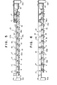
- the supplying apparatus 10 principally comprises a bottom plate 12, a bottom lid A, a mounting plate 13, a mounting frame 14, an air cylinder 15 and an anchor plate 16, as shown in Figs. 1, 4 and 5.
- the bottom plate 12 is designed so that as shown in Figs. 4 and 5, an elongated plate 12b in the form of a gate in section extends over side plates 12a which are pivotally mounted on the pivotal arms 11.
- Rotational shafts 17 are juxaposed at predetermined intervals on the elongated plate 12b and on one projecting end of each shaft 17 is a small bottom lid, all of the small bottom lids thereby constituting a bottom lid A.
- Operating arms 18 are respectively, connected to the rotational shafts 17, respectively as shown in Figs. 5 and 6, and engaging rollers 19 are provided respectively on the ends of the operating arms 18.
- the engaging plate 16" comprises engaging pieces 16b which are parallel to each other and are spaced at predetermined intervals on a horizontal plate 16a.
- Plate 16a is parallel to and below the bottom plate 12, the horizontal plate 16a having one end connected to an air cylinder 15 provided on the end of the bottom plate 12.
- the air cylinder 15- is designed so that when it is at one end of its stroke, corresponding to an OFF position, it is extended and each engaging piece 16b urges each engaging roller 19 to keep arm 18 in a position in which each small bottom lid closes the space between its neighbours (Fig. 5), and when the piston at the other end of its stroke, the ON position, it is withdrawn to dissengage each engaging piece 16b from each engaging roller 19 and each small bottom lid moves to an open position by its own weight (Fig. 6).
- a mounting plate 13 as shown in Figs. 1 and 2 stands upright on the bottom plate 12, and a mounting frame 14 extends over the mounting plate 13.
- the mounting frame 14 is composed of a front plate portion 14a, a side plate portion 14b and an upper plate portion 14c so that a box C filled with filter plugs can be placed on the mounting frame 14 as indicated by the broken lines in Fig. 2 and maintained so as to be reversed into the position as indicated by the solid lines.
- the apparatus described operates as follows: First, the consumption of the mass of filter plugs B within the hopper 1 to such an extent that the hopper needs to be replenished is detected by means of a detector or visually. Subsequently, the box C filled with filter plugs is fitted on mounting frame 14 as indicated by the broken lines in Fi g. 2 and is inverted as indicated by the solid lines. At that time, the air cylinder 15 is in the OFF condition as shown in FIG 5, and the bottom lid A is closed preventing the filter plugs from falling from the bottom of box C which is otherwise open. Then, the level of the box C is adjusted to the upper surface of the filter plugs B within the hopper 1, and the air cylinder 15 is turned ON.
- the apparatus is designed so that each of the small bottom lids a is opened by its own weight, it is to be noted that a torsional coil spring may be provided on each of the small bottom lids a, so that the lid may be urged by spring pressure in the direction of opening.
- the controller 3 periodically turns on and off the air cylinder 15 during the time the small bottom lids a are opened and the lids a may be pi-votally moved .back and forth continuously or from time to time with stroke of S in Fig. 8.
- Other mechanical structures of this embodiment are substantially the same as those of the first embodiment, and explanation thereof will be omitted.
- the air cylinder 15 is periodically turned on and off by the controller 3 and the small bottom lids a are pivotally moved with the stroke S.
- the filter plugs B are preferentially supplied to the depressed portion of the surface of the mass of plugs in the hopper.
- the portion where the filter plugs B are preferentially supplied within the box C corresponds to the said depressed portion, but the small bottom lids a are pivotally moved whereby the filter plugs B within the box C are forcibly distributed in the box C and the upper surface of the filter plugs B in the hopper becomes flat.
Landscapes
- Filling Or Emptying Of Bunkers, Hoppers, And Tanks (AREA)
- Manufacturing Of Cigar And Cigarette Tobacco (AREA)
Priority Applications (1)
| Application Number | Priority Date | Filing Date | Title |
|---|---|---|---|
| EP91114133A EP0461679B1 (fr) | 1986-03-31 | 1987-03-27 | Appareil pour l'alimentation d'articles en forme de tige dans une trémie |
Applications Claiming Priority (2)
| Application Number | Priority Date | Filing Date | Title |
|---|---|---|---|
| JP73166/86 | 1986-03-31 | ||
| JP61073166A JPS62230529A (ja) | 1986-03-31 | 1986-03-31 | 棒状物供給装置の蓋板開閉機構 |
Related Child Applications (1)
| Application Number | Title | Priority Date | Filing Date |
|---|---|---|---|
| EP91114133.1 Division-Into | 1991-08-23 |
Publications (3)
| Publication Number | Publication Date |
|---|---|
| EP0241789A2 true EP0241789A2 (fr) | 1987-10-21 |
| EP0241789A3 EP0241789A3 (en) | 1989-04-19 |
| EP0241789B1 EP0241789B1 (fr) | 1993-01-27 |
Family
ID=13510301
Family Applications (2)
| Application Number | Title | Priority Date | Filing Date |
|---|---|---|---|
| EP87104599A Expired - Lifetime EP0241789B1 (fr) | 1986-03-31 | 1987-03-27 | Appareil pour l'alimentation d'articles en forme de tige dans une trémie |
| EP91114133A Expired - Lifetime EP0461679B1 (fr) | 1986-03-31 | 1987-03-27 | Appareil pour l'alimentation d'articles en forme de tige dans une trémie |
Family Applications After (1)
| Application Number | Title | Priority Date | Filing Date |
|---|---|---|---|
| EP91114133A Expired - Lifetime EP0461679B1 (fr) | 1986-03-31 | 1987-03-27 | Appareil pour l'alimentation d'articles en forme de tige dans une trémie |
Country Status (4)
| Country | Link |
|---|---|
| US (1) | US4821746A (fr) |
| EP (2) | EP0241789B1 (fr) |
| JP (1) | JPS62230529A (fr) |
| DE (2) | DE3752153T2 (fr) |
Cited By (2)
| Publication number | Priority date | Publication date | Assignee | Title |
|---|---|---|---|---|
| EP0443982A1 (fr) * | 1990-02-20 | 1991-08-28 | Fabriques De Tabac Reunies S.A. | Procédé et dispositif de retenue pour une trémie de distribution, notamment de distribution de cigarettes |
| WO2008138636A3 (fr) * | 2007-05-12 | 2009-01-15 | Hauni Maschinenbau Ag | Magasin de vidage et dispositif de transfert pour dispositif de vidage de caissons, dispositif de vidage de caissons et procédé pour vider des caissons remplis de produits en forme de tige et acheminer ces produits jusqu'à des dispositifs en aval |
Families Citing this family (2)
| Publication number | Priority date | Publication date | Assignee | Title |
|---|---|---|---|---|
| DE102007012697A1 (de) | 2007-03-13 | 2008-09-18 | Hauni Maschinenbau Ag | Entleermagazin für eine Schragenentleereinrichtung zum Entleeren von mit stabförmigen Produkten gefüllten Schragen |
| CN109878787A (zh) * | 2019-02-26 | 2019-06-14 | 成都慧晶机械设备有限公司 | 一种半自动装烟机 |
Family Cites Families (3)
| Publication number | Priority date | Publication date | Assignee | Title |
|---|---|---|---|---|
| FR1395382A (fr) * | 1963-05-21 | 1965-04-09 | Molins Machine Co Ltd | Dispositif pour remplir des boîtes ou analogue avec des cigarettes ou autres articles en forme de tige |
| US3976085A (en) * | 1973-04-23 | 1976-08-24 | Liggett & Myers, Incorporated | Automatic cigarette feed machine |
| JPS60240628A (ja) * | 1984-04-28 | 1985-11-29 | 株式会社東京自働機械製作所 | 棒状物供給装置 |
-
1986
- 1986-03-31 JP JP61073166A patent/JPS62230529A/ja active Granted
-
1987
- 1987-03-25 US US07/029,997 patent/US4821746A/en not_active Expired - Lifetime
- 1987-03-27 DE DE3752153T patent/DE3752153T2/de not_active Expired - Fee Related
- 1987-03-27 EP EP87104599A patent/EP0241789B1/fr not_active Expired - Lifetime
- 1987-03-27 EP EP91114133A patent/EP0461679B1/fr not_active Expired - Lifetime
- 1987-03-27 DE DE8787104599T patent/DE3783797T2/de not_active Expired - Fee Related
Cited By (3)
| Publication number | Priority date | Publication date | Assignee | Title |
|---|---|---|---|---|
| EP0443982A1 (fr) * | 1990-02-20 | 1991-08-28 | Fabriques De Tabac Reunies S.A. | Procédé et dispositif de retenue pour une trémie de distribution, notamment de distribution de cigarettes |
| US5224811A (en) * | 1990-02-20 | 1993-07-06 | Fabriques De Tabac Reunies, S.A. | Restraining device for a hopper |
| WO2008138636A3 (fr) * | 2007-05-12 | 2009-01-15 | Hauni Maschinenbau Ag | Magasin de vidage et dispositif de transfert pour dispositif de vidage de caissons, dispositif de vidage de caissons et procédé pour vider des caissons remplis de produits en forme de tige et acheminer ces produits jusqu'à des dispositifs en aval |
Also Published As
| Publication number | Publication date |
|---|---|
| JPS62230529A (ja) | 1987-10-09 |
| JPH0325381B2 (fr) | 1991-04-05 |
| EP0461679B1 (fr) | 1997-12-29 |
| US4821746A (en) | 1989-04-18 |
| EP0241789B1 (fr) | 1993-01-27 |
| EP0241789A3 (en) | 1989-04-19 |
| DE3783797T2 (de) | 1993-05-19 |
| DE3783797D1 (de) | 1993-03-11 |
| DE3752153D1 (de) | 1998-02-05 |
| DE3752153T2 (de) | 1998-04-16 |
| EP0461679A2 (fr) | 1991-12-18 |
| EP0461679A3 (fr) | 1994-12-07 |
Similar Documents
| Publication | Publication Date | Title |
|---|---|---|
| US4487001A (en) | Apparatus for filling chargers with cigarettes or the like | |
| US3970218A (en) | Cap selecting and feeding mechanism | |
| EP0241789A2 (fr) | Appareil pour l'alimentation d'articles en forme de tige dans une trémie | |
| US5108163A (en) | Apparatus for storing articles | |
| US5743067A (en) | Device for loading storage containers for elongated articles | |
| US4668174A (en) | Apparatus for dividing, rounding, and panning of doughballs | |
| GB1191342A (en) | A Machine for Unloading Trays of Articles | |
| CN106829050B (zh) | 一种垫圈包装机的进料装置 | |
| US4128377A (en) | Unmoulding machine for confectionary products | |
| JPS5944031B2 (ja) | たばこ製造および包装装置 | |
| JPS6359674B2 (fr) | ||
| US3545593A (en) | Feeding out device in storage containers for rod-like parallel articles | |
| US3119520A (en) | Dispenser which presents a cigarette in an erect position | |
| EP0637545B1 (fr) | Trémie d'alimentation de produits délicats en forme de tiges, en particulier dans des machines à empaqueter des cigarettes | |
| NO20001661L (no) | Myntfordeler for myntaktiverte maskiner | |
| US3270903A (en) | Lightweight container handling | |
| KR200192708Y1 (ko) | 견과류 수량제어 공급장치 | |
| US2902186A (en) | Storing and feeding apparatus for cigarette machines or the like | |
| US1121556A (en) | Delivery mechanism for commodities. | |
| US3326145A (en) | Feed frame | |
| US2661133A (en) | Counting and dispensing machine | |
| US2927715A (en) | Dispensing unit for vending machines | |
| US884186A (en) | Cigar-vending machine. | |
| SU1719303A1 (ru) | Устройство дл подачи и распределени патронов на пр дильных машинах | |
| ITBO960252A1 (it) | Dispositivo di prelievo e posa di astucci semirigidi |
Legal Events
| Date | Code | Title | Description |
|---|---|---|---|
| PUAI | Public reference made under article 153(3) epc to a published international application that has entered the european phase |
Free format text: ORIGINAL CODE: 0009012 |
|
| AK | Designated contracting states |
Kind code of ref document: A2 Designated state(s): DE GB IT |
|
| RIN1 | Information on inventor provided before grant (corrected) |
Inventor name: NISHIKIMOTO, TARO Inventor name: ENDO, ISAO C/O TOKYO AUTOMATIC Inventor name: KUMATA, KATSUHIKO C/O TOKYO AUTOMATIC |
|
| PUAL | Search report despatched |
Free format text: ORIGINAL CODE: 0009013 |
|
| AK | Designated contracting states |
Kind code of ref document: A3 Designated state(s): DE GB IT |
|
| 17P | Request for examination filed |
Effective date: 19890605 |
|
| 17Q | First examination report despatched |
Effective date: 19900822 |
|
| ITF | It: translation for a ep patent filed | ||
| GRAA | (expected) grant |
Free format text: ORIGINAL CODE: 0009210 |
|
| AK | Designated contracting states |
Kind code of ref document: B1 Designated state(s): DE GB IT |
|
| XX | Miscellaneous (additional remarks) |
Free format text: TEILANMELDUNG 91114133.1 EINGEREICHT AM 27/03/87. |
|
| REF | Corresponds to: |
Ref document number: 3783797 Country of ref document: DE Date of ref document: 19930311 |
|
| PLBE | No opposition filed within time limit |
Free format text: ORIGINAL CODE: 0009261 |
|
| STAA | Information on the status of an ep patent application or granted ep patent |
Free format text: STATUS: NO OPPOSITION FILED WITHIN TIME LIMIT |
|
| 26N | No opposition filed | ||
| ITTA | It: last paid annual fee | ||
| REG | Reference to a national code |
Ref country code: GB Ref legal event code: 732E |
|
| REG | Reference to a national code |
Ref country code: GB Ref legal event code: IF02 |
|
| PGFP | Annual fee paid to national office [announced via postgrant information from national office to epo] |
Ref country code: GB Payment date: 20030326 Year of fee payment: 17 |
|
| PGFP | Annual fee paid to national office [announced via postgrant information from national office to epo] |
Ref country code: DE Payment date: 20030403 Year of fee payment: 17 |
|
| PG25 | Lapsed in a contracting state [announced via postgrant information from national office to epo] |
Ref country code: GB Free format text: LAPSE BECAUSE OF NON-PAYMENT OF DUE FEES Effective date: 20040327 |
|
| PG25 | Lapsed in a contracting state [announced via postgrant information from national office to epo] |
Ref country code: DE Free format text: LAPSE BECAUSE OF NON-PAYMENT OF DUE FEES Effective date: 20041001 |
|
| GBPC | Gb: european patent ceased through non-payment of renewal fee |
Effective date: 20040327 |
|
| PG25 | Lapsed in a contracting state [announced via postgrant information from national office to epo] |
Ref country code: IT Free format text: LAPSE BECAUSE OF NON-PAYMENT OF DUE FEES Effective date: 20050327 |