EP0241722A2 - Schaltgerät für Laserbündel - Google Patents
Schaltgerät für Laserbündel Download PDFInfo
- Publication number
- EP0241722A2 EP0241722A2 EP87103696A EP87103696A EP0241722A2 EP 0241722 A2 EP0241722 A2 EP 0241722A2 EP 87103696 A EP87103696 A EP 87103696A EP 87103696 A EP87103696 A EP 87103696A EP 0241722 A2 EP0241722 A2 EP 0241722A2
- Authority
- EP
- European Patent Office
- Prior art keywords
- mirror
- laser beam
- switching device
- housing
- beam switching
- Prior art date
- Legal status (The legal status is an assumption and is not a legal conclusion. Google has not performed a legal analysis and makes no representation as to the accuracy of the status listed.)
- Withdrawn
Links
Images

Classifications
-
- B—PERFORMING OPERATIONS; TRANSPORTING
- B23—MACHINE TOOLS; METAL-WORKING NOT OTHERWISE PROVIDED FOR
- B23K—SOLDERING OR UNSOLDERING; WELDING; CLADDING OR PLATING BY SOLDERING OR WELDING; CUTTING BY APPLYING HEAT LOCALLY, e.g. FLAME CUTTING; WORKING BY LASER BEAM
- B23K26/00—Working by laser beam, e.g. welding, cutting or boring
- B23K26/02—Positioning or observing the workpiece, e.g. with respect to the point of impact; Aligning, aiming or focusing the laser beam
- B23K26/06—Shaping the laser beam, e.g. by masks or multi-focusing
- B23K26/067—Dividing the beam into multiple beams, e.g. multifocusing
- B23K26/0673—Dividing the beam into multiple beams, e.g. multifocusing into independently operating sub-beams, e.g. beam multiplexing to provide laser beams for several stations
-
- B—PERFORMING OPERATIONS; TRANSPORTING
- B23—MACHINE TOOLS; METAL-WORKING NOT OTHERWISE PROVIDED FOR
- B23K—SOLDERING OR UNSOLDERING; WELDING; CLADDING OR PLATING BY SOLDERING OR WELDING; CUTTING BY APPLYING HEAT LOCALLY, e.g. FLAME CUTTING; WORKING BY LASER BEAM
- B23K26/00—Working by laser beam, e.g. welding, cutting or boring
- B23K26/02—Positioning or observing the workpiece, e.g. with respect to the point of impact; Aligning, aiming or focusing the laser beam
- B23K26/06—Shaping the laser beam, e.g. by masks or multi-focusing
- B23K26/067—Dividing the beam into multiple beams, e.g. multifocusing
-
- G—PHYSICS
- G02—OPTICS
- G02B—OPTICAL ELEMENTS, SYSTEMS OR APPARATUS
- G02B7/00—Mountings, adjusting means, or light-tight connections, for optical elements
- G02B7/18—Mountings, adjusting means, or light-tight connections, for optical elements for prisms; for mirrors
- G02B7/182—Mountings, adjusting means, or light-tight connections, for optical elements for prisms; for mirrors for mirrors
- G02B7/1821—Mountings, adjusting means, or light-tight connections, for optical elements for prisms; for mirrors for mirrors for rotating or oscillating mirrors
Definitions
- the invention relates generally to laser utilising machinery, and, the invention relates specifically to a laser systems where a plurality of stations share a common lasing unit.
- the light tube system from the laser unit be provided with a beam switcher which, at predetermined intervals, may be activated to re-route the laser beam from a former, straight line path.
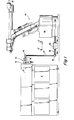
- a floor mounted laser generator unit directs a laser beam to an aperture in a robot base.
- the drawings illustrate a linear cylinder having a single-end position rod with a mirror attached to the rod end, and the cylinder is oriented transversely to the laser beam.
- An angled mirror is carried on the piston rod end and is movable to intercept the laser beam and divert the beam to another robot.
- a laser beam switching device comprising a housing, a beam entry aperture in the housing, a first beam exit aperture in the housing, a second beam exit aperture in the housing, a second beam exit aperture in the housing located out of line with said entry aperture, a mirror means pivotally mounted in said housing, drive means for driving said mirror means between open and closed positions, positive stop means for accurately locating said mirror means in said closed position, and signal means for indicating said open and closed positions.
- the mirror means may be pivoted to said open position to permit a laser beam to pass straight through said housing, and said closed position to divert a laser beam entering said housing through said entry tube, to said second, out of line exit tube.
- the switching device comprises light tubes secured over the entry aperture and the first and second exit apertures, and advantageously the mirror means is pivotally mounted on a pivot rod secured in the housing.
- the housing is hermetically sealed, and advantageously the mirror means comprises a frame, a mirror adjustably mounted on said frame, and means for adjusting the plane of the mirror relative to said frame.
- said frame carries a part-spherical member and the mirror carries a corresponding mating part-spherical member, means being provided to bias said part-spherical surfaces into engagement.
- the beam may be routed to auxiliary units such as laser tools or robots (not shown), connected to an auxiliary light pipe 18c of the beam switching box 20 ( Figure 2).
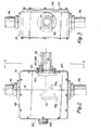
- FIG. 2 The plan view depicted in Figure 2 illustrates the square beam switching box 20 of Figure I, having entry and exit light pipes 18a and 18b secured in position with threaded collars 500 secured to the sides 501, 502 of the box 20.
- one side 503 carries a multi-pin electrical connector 505 for a motor and switches ( Figures 4-8) and the other side 504 carries a threaded collar 500 sealed with an 0-ring 506 and secured with screws 507.
- a side light pipe 18c is threadably received in the collar 500 and held thereto by a locknut 508.
- the box can be secured to a base plate 509 by screws 510 received through the base plate 509 and into the sides 501-504.
- a mirror 511 is pivotable between closed and open positions 511a, 511b to either reflect the laser beam 12 to the side pipe 18c or pass the beam 12 through to the in-line pipe 18b.
- the base plate 509 carries a vertical mounting plate 512 attached to a right angle foot plate 513.
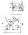
- the vertical mounting plate 51-2 carries a pair of identical right angle bearing blocks 514 on its opposite side, which contain bearings 515 (see Figure 6) to support a vertical pivot rod 516.
- the pivot rod 516 in turn, carries a mirror frame or gate 517, which is a generally square vertical plate having side- extending lugs 518 which are bored to fit the pivot rod 516.
- Saw slots 519 and clamping screws 520 secure the gate 517 to the rod 516.
- the gate 517 is fitted with a pair of fitting washers 521 to take the vertical shake out of the assembly, the lower fitting washer 521 resting against a collar 522 secured to the pivot rod 516.
- the bottom of the pivot rod 516 extends into a flanged bushing 523 in the base plate 509.
- the top of the pivot rod 516 carries a gear 524 secured by a hub set screw 525 tightened against a flat 526 on the rod 516.
- the top of the vertical mounting plate 512 carries a motor mounting bracket 527 which serves to position a drive motor 528 in a vertical attitude.
- the shaft 529 of the drive motor 528 carries a drive pinion 530 secured by a set screw 531, the pinion 530 being in constant mesh with the gear 524.
- FIG. 4 The plan view of Figure 4 shows that the gate 517 is pivotable between the closed position shown in solid, i.e., resting against a closed position stop block 532, and an open position shown in phantom, i.e. resting against an open position stop block 533.
- Three identical switch mounting brackets 534 are secured to the base plate 509, and support identical push button switches 535a, 535b, 535c. Two of the switches 535a, 535b are activated or "made" when the gate 517 is in the closed position, while the third limit switch 535c is activated by bracket 536 (secured to the back of the gate) when the gate 517 is open.
- the closed position of the gate and its control elements are angled with respect to the base plate to that an incoming laser beam 12 will be reflected 90° to the side when the gate is closed, and the beam 12 will flow directly through when the gate 517 is opened.
- the mirror mounting assembly for the mirror gate 517 is shown in Figure 7, where the circular mirror 511 is positioned in the counterbore 537 of a mirror retainer 538, the retainer 538 having a central clearance hole 599 extending therethrough.
- the counterbore 537 is threaded and received on the threaded diameter of a mirror adjusting bracket 540.
- the bracket 540 has a cylindrical flange 541 adjacent to the threaded diameter screwed into the mirror retainer 538, and provided with a stop screw 542 to prevent overtightening of the mirror .511.
- the back face of the mirror adjusting bracket 540 has a counterbore 543 and has a circular facial groove 544 machined into the bottom thereof, in the shape of an incomplete ring with approximately 60 0 between the start and stop points of the groove 544 (see Figure 8).
- a cover plate 545 is seated against the bottom of the counterbore 543 to enclose the groove 544, and a pair of barbed hose fittings 546 are threadably received in the coverplate to provide for coolant flow through the groove 544 when it is desired to cool the mirror 511.
- the outer surface 538a of the mirror retainer 538 is spherical, having a radius swung from the intersection point, or reflecting point 547 of the surface of the mirror 511 at the centreline 548.
- a spherical socket 549 is provided in a square mounting plate 550 secured to the back of the gate 517 and accurately positioned with a fitting washer 551 to establish the correct adjustment to the mirror reflecting point 547.
- the flange 541 of the mirror adjusting bracket 540 has three equally-spaced swivel-pad adjusting screws 552 which bear against the mounting plate 550, and thereby provide an accurate swivel adjustment of the spherical mirror retainer 538.
- a plurality of commercial spring plungers 553, each having a threaded body and spring-loaded nose, are threadably received in the flange 541 to bias the mirror retainer 538 in its spherical socket 549.
- An 0-ring 554 may be provided on the retainer 538 to introduce a slight drag, to prevent slipping, when adjusting the mirror 511.
Landscapes
- Physics & Mathematics (AREA)
- Optics & Photonics (AREA)
- Engineering & Computer Science (AREA)
- Plasma & Fusion (AREA)
- Mechanical Engineering (AREA)
- General Physics & Mathematics (AREA)
- Lasers (AREA)
- Laser Surgery Devices (AREA)
- Mechanical Light Control Or Optical Switches (AREA)
- Laser Beam Processing (AREA)
- Mounting And Adjusting Of Optical Elements (AREA)
Applications Claiming Priority (2)
| Application Number | Priority Date | Filing Date | Title |
|---|---|---|---|
| US84023986A | 1986-03-17 | 1986-03-17 | |
| US840239 | 1986-03-17 |
Publications (2)
| Publication Number | Publication Date |
|---|---|
| EP0241722A2 true EP0241722A2 (de) | 1987-10-21 |
| EP0241722A3 EP0241722A3 (de) | 1989-01-25 |
Family
ID=25281813
Family Applications (1)
| Application Number | Title | Priority Date | Filing Date |
|---|---|---|---|
| EP87103696A Withdrawn EP0241722A3 (de) | 1986-03-17 | 1987-03-13 | Schaltgerät für Laserbündel |
Country Status (3)
| Country | Link |
|---|---|
| EP (1) | EP0241722A3 (de) |
| JP (1) | JPS62275209A (de) |
| DE (1) | DE241722T1 (de) |
Cited By (2)
| Publication number | Priority date | Publication date | Assignee | Title |
|---|---|---|---|---|
| EP0857536A1 (de) * | 1997-02-05 | 1998-08-12 | Honda Giken Kogyo Kabushiki Kaisha | Laserstrahlschweissvorrichtung |
| US7409779B2 (en) | 2005-10-19 | 2008-08-12 | Nike, Inc. | Fluid system having multiple pump chambers |
Families Citing this family (1)
| Publication number | Priority date | Publication date | Assignee | Title |
|---|---|---|---|---|
| DE102009036061B3 (de) | 2009-08-04 | 2011-02-10 | Mtu Friedrichshafen Gmbh | Verfahren zur Steuerung und Regelung einer Brennkraftmaschine |
Family Cites Families (3)
| Publication number | Priority date | Publication date | Assignee | Title |
|---|---|---|---|---|
| DE1102436B (de) * | 1959-05-27 | 1961-03-16 | Fernseh Gmbh | Einrichtung zur Umschaltung optischer Strahlengaenge |
| FR2523363B1 (fr) * | 1982-03-12 | 1986-07-25 | Gentric Alain | Dispositif bistable electromagnetique, application a la realisation de dispositifs de deflexion optique et de dispositifs de commutation notamment optique |
| JPS6096391A (ja) * | 1983-10-28 | 1985-05-29 | Shinkawa Ltd | レ−ザ加工機 |
-
1987
- 1987-03-13 DE DE1987103696 patent/DE241722T1/de active Pending
- 1987-03-13 EP EP87103696A patent/EP0241722A3/de not_active Withdrawn
- 1987-03-17 JP JP6232287A patent/JPS62275209A/ja active Pending
Cited By (3)
| Publication number | Priority date | Publication date | Assignee | Title |
|---|---|---|---|---|
| EP0857536A1 (de) * | 1997-02-05 | 1998-08-12 | Honda Giken Kogyo Kabushiki Kaisha | Laserstrahlschweissvorrichtung |
| US6072149A (en) * | 1997-02-05 | 2000-06-06 | Honda Giken Kogyo Kabushiki Kaisha | Laser beam welding apparatus |
| US7409779B2 (en) | 2005-10-19 | 2008-08-12 | Nike, Inc. | Fluid system having multiple pump chambers |
Also Published As
| Publication number | Publication date |
|---|---|
| DE241722T1 (de) | 1988-02-25 |
| EP0241722A3 (de) | 1989-01-25 |
| JPS62275209A (ja) | 1987-11-30 |
Similar Documents
| Publication | Publication Date | Title |
|---|---|---|
| US6452131B2 (en) | Apparatus and control system for laser welding | |
| US4626999A (en) | Apparatus for controlled manipulation of laser focus point | |
| US4661680A (en) | End-of-arm tooling carousel apparatus for use with a robot | |
| US5685999A (en) | Compact laser machining head with integrated on-line path control for laser machining of material | |
| EP0245608A2 (de) | Vorrichtung zur Zusammenführung von Laserstrahlen | |
| US5961858A (en) | Laser welding apparatus employing a tilting mechanism | |
| US4892992A (en) | Industrial laser robot system | |
| US5132887A (en) | Multi-articulation type robot for laser operation | |
| EP0238307B1 (de) | Gelenk und Vorderarm für Roboterarm | |
| US4607150A (en) | Laser spot welder | |
| US5140129A (en) | Multi-articulated arm type industrial laser robot | |
| US4698479A (en) | Beam delivery system for a CO2 laser | |
| US3993402A (en) | Apparatus for directing a laser beam | |
| WO1993020975A1 (fr) | Machine-outil composite pouvant effectuer un usinage par laser | |
| US4652133A (en) | Vision system with environmental control | |
| KR970005926B1 (ko) | 산업용 레이저 로봇 시스템 | |
| EP0238309B1 (de) | Gelenk- und Unterarmgruppe eines Roboters | |
| EP1170085B1 (de) | Ein fokussierender Kopf für eine Lasermaschine | |
| EP0241722A2 (de) | Schaltgerät für Laserbündel | |
| US5484982A (en) | Beam axis adjusting method for a laser robot | |
| JPH0782154B2 (ja) | レーザービーム等の平行ビームを配送するための装置 | |
| US4698482A (en) | Laser robot | |
| EP0237987B1 (de) | Laserstrahlablenker und Robotervorrichtung mit einem Laserstrahlablenker | |
| JPH04231191A (ja) | デカルト座標系内で移動するための端部作動体 | |
| DE59801154D1 (de) | Roboterhand für die Bearbeitung von Werkstücken mit Laserstrahlung |
Legal Events
| Date | Code | Title | Description |
|---|---|---|---|
| PUAI | Public reference made under article 153(3) epc to a published international application that has entered the european phase |
Free format text: ORIGINAL CODE: 0009012 |
|
| AK | Designated contracting states |
Kind code of ref document: A2 Designated state(s): DE FR GB IT SE |
|
| ITCL | It: translation for ep claims filed |
Representative=s name: JACOBACCI CASETTA & PERANI S.P.A. |
|
| EL | Fr: translation of claims filed | ||
| DET | De: translation of patent claims | ||
| PUAL | Search report despatched |
Free format text: ORIGINAL CODE: 0009013 |
|
| AK | Designated contracting states |
Kind code of ref document: A3 Designated state(s): DE FR GB IT SE |
|
| STAA | Information on the status of an ep patent application or granted ep patent |
Free format text: STATUS: THE APPLICATION IS DEEMED TO BE WITHDRAWN |
|
| 18D | Application deemed to be withdrawn |
Effective date: 19890726 |
|
| RIN1 | Information on inventor provided before grant (corrected) |
Inventor name: HAFFNER, JAMES L. Inventor name: ROSS, TONY LEE |