EP0241666B1 - Gasmess- und Warnvorrichtung - Google Patents
Gasmess- und Warnvorrichtung Download PDFInfo
- Publication number
- EP0241666B1 EP0241666B1 EP87102022A EP87102022A EP0241666B1 EP 0241666 B1 EP0241666 B1 EP 0241666B1 EP 87102022 A EP87102022 A EP 87102022A EP 87102022 A EP87102022 A EP 87102022A EP 0241666 B1 EP0241666 B1 EP 0241666B1
- Authority
- EP
- European Patent Office
- Prior art keywords
- test tube
- photo
- scanning device
- sensor elements
- light
- Prior art date
- Legal status (The legal status is an assumption and is not a legal conclusion. Google has not performed a legal analysis and makes no representation as to the accuracy of the status listed.)
- Expired - Lifetime
Links
- 238000012360 testing method Methods 0.000 claims description 28
- 238000006243 chemical reaction Methods 0.000 claims description 12
- 238000011156 evaluation Methods 0.000 claims description 12
- 238000012634 optical imaging Methods 0.000 claims 7
- 238000003384 imaging method Methods 0.000 description 10
- 239000007789 gas Substances 0.000 description 9
- 238000005259 measurement Methods 0.000 description 3
- 238000013461 design Methods 0.000 description 2
- 230000004075 alteration Effects 0.000 description 1
- 238000011161 development Methods 0.000 description 1
- 230000018109 developmental process Effects 0.000 description 1
- 238000006073 displacement reaction Methods 0.000 description 1
- 238000004880 explosion Methods 0.000 description 1
- 230000002349 favourable effect Effects 0.000 description 1
- 238000012545 processing Methods 0.000 description 1
- 230000005855 radiation Effects 0.000 description 1
- 230000035945 sensitivity Effects 0.000 description 1
- 230000003595 spectral effect Effects 0.000 description 1
- 238000011144 upstream manufacturing Methods 0.000 description 1
Images
Classifications
-
- G—PHYSICS
- G01—MEASURING; TESTING
- G01N—INVESTIGATING OR ANALYSING MATERIALS BY DETERMINING THEIR CHEMICAL OR PHYSICAL PROPERTIES
- G01N21/00—Investigating or analysing materials by the use of optical means, i.e. using sub-millimetre waves, infrared, visible or ultraviolet light
- G01N21/75—Systems in which material is subjected to a chemical reaction, the progress or the result of the reaction being investigated
- G01N21/77—Systems in which material is subjected to a chemical reaction, the progress or the result of the reaction being investigated by observing the effect on a chemical indicator
- G01N21/78—Systems in which material is subjected to a chemical reaction, the progress or the result of the reaction being investigated by observing the effect on a chemical indicator producing a change of colour
- G01N21/783—Systems in which material is subjected to a chemical reaction, the progress or the result of the reaction being investigated by observing the effect on a chemical indicator producing a change of colour for analysing gases
Definitions
- the invention relates to expedient developments of the gas measuring and warning device described in the unpublished European patent application EP-A-0 187 898 (published on July 23, 1986).
- Such a gas measuring and warning device contains a test tube through which the gas to be detected flows, as well as a photoelectric scanning device for the test tube illuminated or illuminated by at least one light source, and has a light-sensitive line of similar sensor elements for tracking a conversion zone traveling through the test tube.
- the photoelectric An evaluation circuit is connected to the scanning device and is controlled by the sensor elements located within the conversion zone in order to emit a measurement signal.
- the photoelectric scanning device also contains imaging optics, which images the test tube onto the light-sensitive line of the sensor elements for outputting an analog output signal.
- the imaging optics To emit low-noise signals from the line of sensor elements, it is necessary to design the imaging optics in such a way that, with good imaging quality, the highest possible light intensity occurs on the surface of the line of sensor elements.
- the imaging error of the imaging optics should be kept small over the entire length of the line of sensor elements and in particular also in the edge areas. All of the measures mentioned below thus serve to design the photoelectric scanning device and in particular the imaging optics contained therein in a device of the type described in the introduction in such a way that a low-noise, high-resolution measurement signal can be taken from the row of sensor elements.
- the imaging optics contain a cylindrical lens, the cylinder axis of which is parallel to the longitudinal axis of the test tube and to the row of sensor elements.
- the reduced real intermediate image of the cylindrical lens is then imaged on the sensor line through an image lens, preferably through an achromatic lens.
- an achromatic device appears expedient because it largely compensates for the focal point shift caused by spherical and chromatic aberration.
- an achromatic lens as an image lens, it is ensured that the band of the focal points resulting from displacement is not wider than the average distance between two sensor elements.
- a further additional improvement can be achieved in a manner known per se, if appropriate, by means of an aperture upstream of the achromatic lens, which, for example, limits the aperture ratio to 2: 1.
- a high light intensity on the surface of the row of sensor elements can advantageously be achieved in that instead of a continuous light source, a light source is provided which is designed to emit light pulses. This impulse keying of the light source allows high light intensities to be reached for a short time. Taking into account the spectral composition of the radiation from the light source, the use of a gas discharge lamp appears to be particularly favorable.
- the quality of the image can be further improved by switching on an interference filter between the cylindrical lens and the achromatic lens. In this way, a contrast increase between the fumigated and non-fumigated part can be achieved in the test tubes.
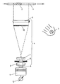
- a conversion zone 2 is located in a test tube 1.
- the test tube 1 is illuminated by a gas discharge lamp 3 mounted on the side.
- An imaging optics 4 contains a cylindrical lens 5, the cylinder axis of which is parallel to the longitudinal axis of the test tube 1 and to a diode row 6.
- An interference filter 7, an aperture 8 and an achromat 9 are also provided in the imaging optics 4.
- the gas discharge lamp 3, the imaging optics 4 and the diode array 6 together form the photoelectric scanning device.
- the cylindrical lens 5 generates a reduced real intermediate image of the test tube 1 or of its conversion zone, which is indicated at position 10. This real intermediate image is mapped onto the length of the diode row 6 by the achromat 9 with the interposition of the interference filter 7 and the diaphragm 8.
- the output signals of the diode row 6 are input into an evaluation circuit 11, not shown in the drawing, which enables the diode row to be read out at a correspondingly predetermined time interval by means of a built-in shift register.
- the evaluation circuit contains a preamplifier and an analog-digital converter which digitally converts the read signals from the diode row 6, as well as a first digital memory in which these signals, which were recorded before any gassing, are stored.
- a second digital memory is also contained in the evaluation circuit, which stores the likewise converted binary sample values after the gassing.
- a digital arithmetic unit for signal processing in the form of a microcomputer is provided, which outputs output values for measurement display in a display device 12 or for triggering a warning signal.
Landscapes
- Physics & Mathematics (AREA)
- Chemical & Material Sciences (AREA)
- Biochemistry (AREA)
- General Health & Medical Sciences (AREA)
- Plasma & Fusion (AREA)
- Health & Medical Sciences (AREA)
- Life Sciences & Earth Sciences (AREA)
- Analytical Chemistry (AREA)
- Engineering & Computer Science (AREA)
- Chemical Kinetics & Catalysis (AREA)
- General Physics & Mathematics (AREA)
- Immunology (AREA)
- Pathology (AREA)
- Investigating Or Analysing Materials By The Use Of Chemical Reactions (AREA)
- Investigating Or Analyzing Non-Biological Materials By The Use Of Chemical Means (AREA)
- Investigating Or Analysing Materials By Optical Means (AREA)
Applications Claiming Priority (2)
| Application Number | Priority Date | Filing Date | Title |
|---|---|---|---|
| DE19863605047 DE3605047C1 (en) | 1985-01-15 | 1986-02-18 | Gas measuring and warning device |
| DE3605047 | 1986-02-18 |
Publications (3)
| Publication Number | Publication Date |
|---|---|
| EP0241666A2 EP0241666A2 (de) | 1987-10-21 |
| EP0241666A3 EP0241666A3 (en) | 1988-04-20 |
| EP0241666B1 true EP0241666B1 (de) | 1991-05-02 |
Family
ID=6294321
Family Applications (1)
| Application Number | Title | Priority Date | Filing Date |
|---|---|---|---|
| EP87102022A Expired - Lifetime EP0241666B1 (de) | 1986-02-18 | 1987-02-13 | Gasmess- und Warnvorrichtung |
Country Status (3)
| Country | Link |
|---|---|
| US (1) | US5057280A (enExample) |
| EP (1) | EP0241666B1 (enExample) |
| JP (1) | JPS62192636A (enExample) |
Families Citing this family (4)
| Publication number | Priority date | Publication date | Assignee | Title |
|---|---|---|---|---|
| US5369284A (en) * | 1993-03-30 | 1994-11-29 | The Charles Stark Draper Laboratory, Inc. | Active edge position measuring device |
| DE4415866C1 (de) * | 1994-05-05 | 1995-06-22 | Draegerwerk Ag | Vorrichtung zum Nachweis von gas- und dampfförmigen Komponenten eines Gasgemisches |
| DE19619391C1 (de) * | 1996-05-14 | 1997-07-03 | Draegerwerk Ag | Verfahren zur Bestimmung des Anteils eines Gases in einer Gasprobe |
| CN107250870B (zh) * | 2015-01-20 | 2020-01-07 | 3I艾姆尹治意大利有限责任公司 | 具有主柱面柱镜的远心光学物镜的图像获取设备 |
Family Cites Families (9)
| Publication number | Priority date | Publication date | Assignee | Title |
|---|---|---|---|---|
| US3074634A (en) * | 1961-04-17 | 1963-01-22 | Ibm | Pattern recognition |
| US3678192A (en) * | 1969-08-13 | 1972-07-18 | Nippon Steel Corp | Method and apparatus for digital measurement with an industrial television |
| US3909519A (en) * | 1972-11-10 | 1975-09-30 | Jr Lewis C Page | Measuring system |
| DE2628790C2 (de) * | 1976-06-26 | 1978-07-06 | Draegerwerk Ag, 2400 Luebeck | Gasmeß- und Warnvorrichtung mit einem von dem nachzuweisenden Gas durchströmten Prüfröhrchen |
| US4063821A (en) * | 1976-07-19 | 1977-12-20 | General Kinetics, Incorporated | Gas detector tube reader |
| CA1085647A (en) * | 1978-03-07 | 1980-09-16 | Noranda Mines Limited | Apparatus for detecting the presence of a specific substance in a gas stream |
| DE2814843C2 (de) * | 1978-04-06 | 1980-05-29 | Draegerwerk Ag, 2400 Luebeck | Gasmeß- und Warnvorrichtung |
| AU588245B2 (en) * | 1984-06-13 | 1989-09-14 | Inverness Medical Switzerland Gmbh | Devices for use in chemical test procedures |
| DE3501093C1 (de) * | 1985-01-15 | 1986-06-12 | Drägerwerk AG, 2400 Lübeck | Gasmess- und Warnvorrichtung |
-
1987
- 1987-02-10 US US07/012,895 patent/US5057280A/en not_active Expired - Fee Related
- 1987-02-13 EP EP87102022A patent/EP0241666B1/de not_active Expired - Lifetime
- 1987-02-16 JP JP62031658A patent/JPS62192636A/ja active Granted
Also Published As
| Publication number | Publication date |
|---|---|
| EP0241666A2 (de) | 1987-10-21 |
| JPH0321864B2 (enExample) | 1991-03-25 |
| US5057280A (en) | 1991-10-15 |
| EP0241666A3 (en) | 1988-04-20 |
| JPS62192636A (ja) | 1987-08-24 |
Similar Documents
| Publication | Publication Date | Title |
|---|---|---|
| DE2451301C2 (de) | Radiographieapparat mit einer Gruppe von Hauptdetektoren zum Empfangen von zu einem ebenen Bündel kollimierter Röntgenstrahlung und mit zusätzlichen, außerhalb des Bündels angeordneten Detektoreinrichtungen | |
| DE2740724C3 (de) | Spektralphotometer | |
| DE2737554A1 (de) | Vorrichtung zur haertepruefung | |
| EP1160719B1 (de) | Sensor für die Echtheitserkennung von Signets auf Dokumenten | |
| DE2433683A1 (de) | Vorrichtung zur ueberwachung einer materialbahn auf fehlstellen | |
| DE3109270A1 (de) | Anordnung zur flascheninspektion | |
| DE2433682A1 (de) | Vorrichtung zur ueberwachung einer materialbahn oder einer sonstigen abtastebene | |
| EP0241666B1 (de) | Gasmess- und Warnvorrichtung | |
| DE2516756A1 (de) | Verfahren und vorrichtung zur bestimmung einer flaechenabmessung in einer ebene | |
| DE60036467T2 (de) | Verfahren und vorrichtung zur dopplergeschwindigkeitsmessung | |
| DE2938844A1 (de) | Verfahren zur auswertung optischer spektren | |
| DE4137551A1 (de) | Anordnung zur verbesserung der sicht, insbesondere in fahrzeugen | |
| DE102011015478B4 (de) | Vorrichtung und Verfahren zur Erfassung und Analyse von Laserstrahlung | |
| DE2827705C3 (de) | Gerät zur Feststellung von Fehlern an Bahnmaterial | |
| DE2840867C2 (de) | Gasmeßvorrichtung mit einem von dem nachzuweisenden Gas durchströmten Prüfröhrchen | |
| DE19646236A1 (de) | Vorrichtung zur endoskopischen Diagnose und Behandlung von Gewebe | |
| DE3605047C1 (en) | Gas measuring and warning device | |
| DE3501093C1 (de) | Gasmess- und Warnvorrichtung | |
| EP0281750A2 (de) | Optische Abtastvorrichtung mit telezentrischer Zeilenkamera | |
| DE4137724A1 (de) | Digitales radiographiesystem mit einer roentgenstrahl-bildverstaerkerroehre | |
| DE4015623C2 (enExample) | ||
| EP1523667A1 (de) | Dunkelfeld-abbildungsvorrichtung zur ortsaufgelösten dunkelfeldabbildung einer probe und untersuchungsverfahren | |
| EP0281795A1 (de) | Verfahren zum Abtasten eines zeitlich veränderlichen elektrischen Signals sowie Vorrichtung zur Durchführung und Anwendung des Verfahrens | |
| DE4429383A1 (de) | Verfahren und Vorrichtung zur zeit- und ortsaufgelösten Fluoreszenz- bzw. Streulicht-Spektroskopie | |
| DE9421717U1 (de) | Vorrichtung zur zeit- und ortsaufgelösten Fluoreszenz- bzw. Streulicht-Spektroskopie |
Legal Events
| Date | Code | Title | Description |
|---|---|---|---|
| PUAI | Public reference made under article 153(3) epc to a published international application that has entered the european phase |
Free format text: ORIGINAL CODE: 0009012 |
|
| 17P | Request for examination filed |
Effective date: 19870304 |
|
| AK | Designated contracting states |
Kind code of ref document: A2 Designated state(s): FR GB NL |
|
| PUAL | Search report despatched |
Free format text: ORIGINAL CODE: 0009013 |
|
| RHK1 | Main classification (correction) |
Ipc: G01N 21/78 |
|
| AK | Designated contracting states |
Kind code of ref document: A3 Designated state(s): FR GB NL |
|
| 17Q | First examination report despatched |
Effective date: 19900810 |
|
| GRAA | (expected) grant |
Free format text: ORIGINAL CODE: 0009210 |
|
| AK | Designated contracting states |
Kind code of ref document: B1 Designated state(s): FR GB NL |
|
| GBT | Gb: translation of ep patent filed (gb section 77(6)(a)/1977) | ||
| ET | Fr: translation filed | ||
| PGFP | Annual fee paid to national office [announced via postgrant information from national office to epo] |
Ref country code: GB Payment date: 19920124 Year of fee payment: 6 |
|
| PGFP | Annual fee paid to national office [announced via postgrant information from national office to epo] |
Ref country code: FR Payment date: 19920206 Year of fee payment: 6 |
|
| PGFP | Annual fee paid to national office [announced via postgrant information from national office to epo] |
Ref country code: NL Payment date: 19920229 Year of fee payment: 6 |
|
| PLBE | No opposition filed within time limit |
Free format text: ORIGINAL CODE: 0009261 |
|
| STAA | Information on the status of an ep patent application or granted ep patent |
Free format text: STATUS: NO OPPOSITION FILED WITHIN TIME LIMIT |
|
| 26N | No opposition filed | ||
| PG25 | Lapsed in a contracting state [announced via postgrant information from national office to epo] |
Ref country code: GB Effective date: 19930213 |
|
| PG25 | Lapsed in a contracting state [announced via postgrant information from national office to epo] |
Ref country code: NL Effective date: 19930901 |
|
| GBPC | Gb: european patent ceased through non-payment of renewal fee |
Effective date: 19930213 |
|
| NLV4 | Nl: lapsed or anulled due to non-payment of the annual fee | ||
| PG25 | Lapsed in a contracting state [announced via postgrant information from national office to epo] |
Ref country code: FR Effective date: 19931029 |
|
| REG | Reference to a national code |
Ref country code: FR Ref legal event code: ST |