EP0241474B1 - A scraping device in a settling basin - Google Patents
A scraping device in a settling basin Download PDFInfo
- Publication number
- EP0241474B1 EP0241474B1 EP86901161A EP86901161A EP0241474B1 EP 0241474 B1 EP0241474 B1 EP 0241474B1 EP 86901161 A EP86901161 A EP 86901161A EP 86901161 A EP86901161 A EP 86901161A EP 0241474 B1 EP0241474 B1 EP 0241474B1
- Authority
- EP
- European Patent Office
- Prior art keywords
- scraping blade
- scraping
- sledge
- basin
- carrier
- Prior art date
- Legal status (The legal status is an assumption and is not a legal conclusion. Google has not performed a legal analysis and makes no representation as to the accuracy of the status listed.)
- Expired - Lifetime
Links
Images

Classifications
-
- B—PERFORMING OPERATIONS; TRANSPORTING
- B01—PHYSICAL OR CHEMICAL PROCESSES OR APPARATUS IN GENERAL
- B01D—SEPARATION
- B01D21/00—Separation of suspended solid particles from liquids by sedimentation
- B01D21/02—Settling tanks with single outlets for the separated liquid
- B01D21/04—Settling tanks with single outlets for the separated liquid with moving scrapers
-
- B—PERFORMING OPERATIONS; TRANSPORTING
- B01—PHYSICAL OR CHEMICAL PROCESSES OR APPARATUS IN GENERAL
- B01D—SEPARATION
- B01D21/00—Separation of suspended solid particles from liquids by sedimentation
- B01D21/18—Construction of the scrapers or the driving mechanisms for settling tanks
Definitions
- the present invention relates to a scraping device in a settling basin.
- the scraping device removes sediments, which accumulate on the bottom of the basin. It comprises a vehicle and a scraper on the vehicle.
- a cable drive device having a pull cable pulls the vehicle forwards and backwards along the bottom of the basin.
- the scraper assumes, in one of the vehicle's two directions of moment, a working position, in which it is directed towards the bottom of the basin, in order to scrape sediment to an output area, and in the vehicle's opposite direction a passive return position, in which it is elevated from the bottom of the basin.
- Swedish allowed patent application no. 8302563-5 relates to a quite simple scraping device, which includes a vehicle, on which two scraping blades adjacent each other are pivotally disposed. Shoulders, which are arranged at the turning points of the vehicle, turn the scraping blades into their intended positions, either an active scraping position or an elevated passive idle or return position.
- the pull cable is connected partly to the front end of the vehicle and partly to its other end.
- One object of the present invention is to build a scraping device, which is simpler than known scraping devices and comprises few movable parts.
- Another object of the invention is to build a scraping device, which can be connected, in a ready manner, to several scraping devices, which are identical with it and jointly in succession in the direction of movement are capable of removing sediments from the bottom of a settling basin, particularly an extended one.
- the scraping device comprises a sledge on a guide on the bottom of a settling basin as well as a carrier, which is rotatably disposed on the sledge and carries a scraping blade into at first an active working position for sediment scraping towards an output area and then an elevated passive rest or return position, when the scraping device is pulled away from the output area after the working phase.
- the carrier turns the scraping blade into its intended position, because the pull cable is provided with a holder in the carrier.
- the pull cable performs two tasks, partly of pulling the sledge in the working direction and the return direction and partly of lowering the scraping blade at the return points of the scraping device, at first into the working position and then into the return position.
- the pull cable can accomplish this while pulling and at the same time guiding without any such additional mechanical regulatory devices, which known scraping devices employ.
- the sledge which carries the carrier and the scraping blade attached to the carrier comprises a profiled bar. Its cross section or the cross section of sliding shoes, which are inserted into it, has such a shape, that it cannot be elevated from or run off its guide.
- the carrier is rotatably disposed around an axle on the sledge. Said axle is horizontally disposed and its direction is perpendicular to the direction of movement of the scraping device.
- the scraping blade which is attached to the carrier, is carried to its active working position, when the pull cable pulls the carrier towards the output area of the basin and subsequently to its passive rest and return position, when the pull cable pulls the carrier in the opposite direction, in order not to scrape the amount of sediment, which has been fed or scraped towards the output area, away from the output area or scrape newly settled material in the wrong direction.
- the two ends of the scraping blade are provided with wheels, which support the sledge and the advance of the scraping blade along the bottom of the basin.
- the axles of the wheels were extended towards the sledge, they would coincide with the axle of the carrier on the sledge.
- the wheels are always in touch with the bottom of the basin, regardless of what the angle between the scraping blade and the bottom of the basin is.
- the inventor was at first not successful with the concept of employing a carrier for the scraping blade and a holder on the carrierfor the pull cable due to the fact that the scraping blade was not elevated but was instead locked in its working position, when the pull cable pulled the carrier away from the output area and thus, the scraping device left the output area having its scraping blade in the working psoition.
- This problem was solved with a preferred embodiment of the present invention by providing such a large friction between the sledge and the guide, that the scraping blade, by means of its pull cable and carrier, without difficulty, could be brought to its return position without the friction between the sledge and the guide being overcome.
- the required friction can be attained by choosing a suitable material for partly the interior parts of the sledge and partly the guide.
- the sledge is provided with interior sliding shoes at its two ends. The sliding shoes seize the guide in order to keep the sledge on the guide and at the same time they provide such an intimate contact between the sledge and the guide and are made of such a material that the required contact is attained.
- the scraping blade roughly has the same density as the density of the liquid medium in the settling basin.
- the force needed to atfirst lower the scraping blade into its working position and subsequently elevate it into its return position consequently is small and the required least friction between the sledge and its guide correspondingly may be made smaller.
- the pulling force have to be 10 kg subsequenttothe starting of the sledge, provided the scraping blade is substantially weightless in the liquid medium in the basin.
- the pulling force maybe must be 30 kg in order to initiate the movement of the sledge.
- a pulling force of about the same dimension can be used to move the carrier and the scraping blade into their intended working and return position respectively before the start of the scraping device in its working and its return direction respectively.
- the desired density of the scraping blade can be attained according to the present invention by one of the following measures:
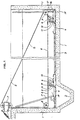
- Fig. 1 shows a longitudinal section of a settling basin 1.
- an output area 2 or a sludge hopper 2 is provided in its left end.
- a scraping sledge 4 is mounted to be moved forwards and backwards by means of a pull cable 5, which is attached to a carrier 6, which is mounted on a scraping sledge 4.
- the pull cable is driven over two separate cable drums in a cable drive device 7, which is mounted above the basin. Cable 5 pulls carrier 6 and scraping sledge 4 via a pulley wheel 8 towards sludge hopper 2 or via pulley wheel 9 towards the opposite end of settling basin 1.
- a scraping blade 10 is firmly attached to carrier 6 and extends from one longitudinal wall to the other in basin 1 in a direction, which is perpendicular to the direction of pull cable 5.
- Carrier 6 is rotatably disposed on the sledge around an axle 12 on the sledge and scraping blade 10 can stay in two terminal positions, partly in one working position, when its longitudinal edge touches the bottom of basin 1 and a sediment scraping of the bottom can be performed, and partly in an elevated position, a rest or return position (the scraping blade being depicted by dotted lines), when scraping blade 10 jointly with carrier 6 on sledge 4 returns to the right end of basin 1.
- a limit actuator 16 on the left end of sledge 4 will contact a limit breaker 17 and drive device 7 change its direction.
- Sledge 4 is provided with a U-shaped sliding shoe 18 at each end, which seizes guide 3 and at the same time cause friction between sledge 4 and guide 3.
- carrier 6 will initially turn to the right and consequently elevates scraping blade 10 into a rest or return position.
- Scraping blade 10 is provided eith a layer 11 of a plastic foam and consequently the density of scraping blade 10, 11 is roughly the same as the density of the liquid medium in the basin and thus, substantially no moment of force is needed to turn scraping blade 10 to the right.
- a second limit breaker 17 is located here and it is actuated by a second limit actuator 16 on the right end of sledge 4, when the sledge wholly has reached its right end position and consequently drive device 7 changes its direction, cable 5 starts pulling carrier 6 and scraping blade 10 with its plastic layer 11 is lowered towards the bottom of basin 1, since the weight of the scraping blade in the liquid medium substantially can be disregarded.
- Fig. 2 shows scraping sledge 4 and its two sliding shoes 18 on guide 3 and axle 12, around which carrier 6 is rotatably disposed.
- Carrier 6 carries scraping blade 10, which as depicted assumes its working position, one of its longitudinal edges being in contact with the bottom of basin 1.
- Two supporting wheels 13 are attached to the two ends of scraping blade 10. If their shafts were to be extended towards axle 12 of the sledge, they would coincide with with the latter. Thus, wheels 13 always are in contact with the bottom of basin 1, regardless of what the angle is between scraping blade 10 and the bottom of the basin.
- Fig. 3 shows in planar view a scraping device 4, 6, 10.
- Scraping blade 10 has the same position, working position, as in fig. 2.
- Fig. 4 is a vertical cross section of an end of scraping sledge 4, which shows a sliding shoe 18 between guide 3 and sledge 4.
- the counter pressure of the sledge, which is needed to guide the scraping blade by means of pull cable 5 is attained by friction between the two sliding shoes (only one shown) and guide 3.
- Fig. 5 shows the position of a sliding shoe 18 on guide 3 and in one end of scraping sledge 4. It is attached to the interior of scraping sledge 4. This figure also shows one of the two limit actuators 16 on this end of the sledge as well as the lower end of a limit breaker 17.
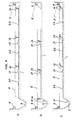
- Fig. 6 shows only schematically three different conditions of an extended scraping construction having three scraping sledges according to the invention, which in succession are connected to a pull cable in the direction of the pull cable.
Abstract
Description
- The present invention relates to a scraping device in a settling basin. The scraping device removes sediments, which accumulate on the bottom of the basin. It comprises a vehicle and a scraper on the vehicle. A cable drive device having a pull cable pulls the vehicle forwards and backwards along the bottom of the basin. The scraper assumes, in one of the vehicle's two directions of moment, a working position, in which it is directed towards the bottom of the basin, in order to scrape sediment to an output area, and in the vehicle's opposite direction a passive return position, in which it is elevated from the bottom of the basin.
- Known scraping devices for removal of sediments in rectangularly shaped settling basins are rather complicated structures having a plurality of movable parts.
- Swedish allowed patent application no. 8302563-5 relates to a quite simple scraping device, which includes a vehicle, on which two scraping blades adjacent each other are pivotally disposed. Shoulders, which are arranged at the turning points of the vehicle, turn the scraping blades into their intended positions, either an active scraping position or an elevated passive idle or return position. The pull cable is connected partly to the front end of the vehicle and partly to its other end.
- One object of the present invention is to build a scraping device, which is simpler than known scraping devices and comprises few movable parts.
- Another object of the invention is to build a scraping device, which can be connected, in a ready manner, to several scraping devices, which are identical with it and jointly in succession in the direction of movement are capable of removing sediments from the bottom of a settling basin, particularly an extended one.
- These objects are attained in accordance with
claims 1 and 5, which are enclosed. - The scraping device according to the present invention comprises a sledge on a guide on the bottom of a settling basin as well as a carrier, which is rotatably disposed on the sledge and carries a scraping blade into at first an active working position for sediment scraping towards an output area and then an elevated passive rest or return position, when the scraping device is pulled away from the output area after the working phase. The carrier turns the scraping blade into its intended position, because the pull cable is provided with a holder in the carrier. Thus, the pull cable performs two tasks, partly of pulling the sledge in the working direction and the return direction and partly of lowering the scraping blade at the return points of the scraping device, at first into the working position and then into the return position. The pull cable can accomplish this while pulling and at the same time guiding without any such additional mechanical regulatory devices, which known scraping devices employ.
- The sledge, which carries the carrier and the scraping blade attached to the carrier comprises a profiled bar. Its cross section or the cross section of sliding shoes, which are inserted into it, has such a shape, that it cannot be elevated from or run off its guide. The carrier is rotatably disposed around an axle on the sledge. Said axle is horizontally disposed and its direction is perpendicular to the direction of movement of the scraping device. The scraping blade, which is attached to the carrier, is carried to its active working position, when the pull cable pulls the carrier towards the output area of the basin and subsequently to its passive rest and return position, when the pull cable pulls the carrier in the opposite direction, in order not to scrape the amount of sediment, which has been fed or scraped towards the output area, away from the output area or scrape newly settled material in the wrong direction.
- In order to prevent the sledge and its carrier and scraping blade from tilting and turning over in relation to the guide, despite the fact that the sledge is retained in its position by the guide thanks to the profiling of the sledge or its sliding shoes, the two ends of the scraping blade are provided with wheels, which support the sledge and the advance of the scraping blade along the bottom of the basin. In case the axles of the wheels were extended towards the sledge, they would coincide with the axle of the carrier on the sledge. Thus, the wheels are always in touch with the bottom of the basin, regardless of what the angle between the scraping blade and the bottom of the basin is.
- The inventor was at first not successful with the concept of employing a carrier for the scraping blade and a holder on the carrierfor the pull cable due to the fact that the scraping blade was not elevated but was instead locked in its working position, when the pull cable pulled the carrier away from the output area and thus, the scraping device left the output area having its scraping blade in the working psoition. This problem was solved with a preferred embodiment of the present invention by providing such a large friction between the sledge and the guide, that the scraping blade, by means of its pull cable and carrier, without difficulty, could be brought to its return position without the friction between the sledge and the guide being overcome. When the pulling power exerted on the cable increased subsequent to the turning and the lowering respectively of the scraping blade into the intended position, the friction was at last overcome and the sledge was removed aong the guide away from the output area. The artisan knows that the friction in general is from 1.5 to 5 times larger in a rest position than in running and hence, the required friction is not too damaging to the movement of the sledge of the scraping device along its guide.
- The required friction can be attained by choosing a suitable material for partly the interior parts of the sledge and partly the guide. Preferably, the sledge is provided with interior sliding shoes at its two ends. The sliding shoes seize the guide in order to keep the sledge on the guide and at the same time they provide such an intimate contact between the sledge and the guide and are made of such a material that the required contact is attained.
- In a preferred embodiment of the present invention the scraping blade roughly has the same density as the density of the liquid medium in the settling basin. The force needed to atfirst lower the scraping blade into its working position and subsequently elevate it into its return position consequently is small and the required least friction between the sledge and its guide correspondingly may be made smaller.
- In case the sledge weighs e.g. 100 kg, the pulling force have to be 10 kg subsequenttothe starting of the sledge, provided the scraping blade is substantially weightless in the liquid medium in the basin. The pulling force maybe must be 30 kg in order to initiate the movement of the sledge. Apparently, a pulling force of about the same dimension can be used to move the carrier and the scraping blade into their intended working and return position respectively before the start of the scraping device in its working and its return direction respectively.
- The desired density of the scraping blade can be attained according to the present invention by one of the following measures:
- 1. The scraping blade proper is made of a material having a low density, e.g. a tough plastic material having a low density. The low density is attained e.g. by giving the material a certain porosity, in a manner known per se; and
- 2. The scraping blade can be provided with an extra layer of a material, which is fixed to the blade, the density of the scraping blade and of the extra layer being jointly roughly as large as the density of the liquid medium.
- A preferred embodiment of the present invention is to be described more in detail as follows, reference being made to the enclosed drawings. The drawings also relate to a preferred embodiment of a scraping device having a plurality of scrapers according to the invention.
- Fig. 1 shows a longitudinal section of a settling basin, partly its end having an output area and partly its opposite end, and it also depicts a sledge according to the invention in its two terminal positions;
- Fig. 2 shows a cross section of the same basin with a view towards its output area;
- Fig. 3 is a planar view of the same scraping sledge in its basin;
- Fig. 4 shows a cross section of the scraping sledge in figs. 1-3 and its guide;
- Fig. 5 is an elevational view of one end of the same scraping sledge as well as a limit actuator; and
- Fig. 6 shows three longitudinal sections of a schematically represented settling basin having a scraping device comprising three cooperative scraping sledges according to the invention.
- Fig. 1 shows a longitudinal section of a settling basin 1. In its left end an
output area 2 or asludge hopper 2 is provided. Along aguide 3 in the middle of basin 1 ascraping sledge 4 is mounted to be moved forwards and backwards by means of apull cable 5, which is attached to acarrier 6, which is mounted on ascraping sledge 4. The pull cable is driven over two separate cable drums in a cable drive device 7, which is mounted above the basin.Cable 5pulls carrier 6 and scrapingsledge 4 via apulley wheel 8 towardssludge hopper 2 or viapulley wheel 9 towards the opposite end of settling basin 1. Ascraping blade 10 is firmly attached tocarrier 6 and extends from one longitudinal wall to the other in basin 1 in a direction, which is perpendicular to the direction ofpull cable 5.Carrier 6 is rotatably disposed on the sledge around anaxle 12 on the sledge and scrapingblade 10 can stay in two terminal positions, partly in one working position, when its longitudinal edge touches the bottom of basin 1 and a sediment scraping of the bottom can be performed, and partly in an elevated position, a rest or return position (the scraping blade being depicted by dotted lines), when scrapingblade 10 jointly withcarrier 6 onsledge 4 returns to the right end of basin 1. - When
sledge 4 has arrived at its turning point atsludge hopper 2, alimit actuator 16 on the left end ofsledge 4 will contact alimit breaker 17 and drive device 7 change its direction. Sledge 4 is provided with aU-shaped sliding shoe 18 at each end, which seizesguide 3 and at the same time cause friction betweensledge 4 andguide 3. Thus, whencable 5 pulls to the right,carrier 6 will initially turn to the right and consequently elevatesscraping blade 10 into a rest or return position. Scrapingblade 10 is provided eith alayer 11 of a plastic foam and consequently the density ofscraping blade scraping blade 10 to the right. Subsequently the friction between the two slidingshoes 18 ofsledge 4 andguide 3 must be overcome, before sledge 4 and itscarrier 6 and scrapingblade 10 can be pulled towards the opposite end of basin 1. Asecond limit breaker 17 is located here and it is actuated by asecond limit actuator 16 on the right end ofsledge 4, when the sledge wholly has reached its right end position and consequently drive device 7 changes its direction,cable 5starts pulling carrier 6 andscraping blade 10 with itsplastic layer 11 is lowered towards the bottom of basin 1, since the weight of the scraping blade in the liquid medium substantially can be disregarded. After thatsledge 4 is pulled to the left, when the friction between slidingshoes 18 of the sledge andguide 3 is overcome and hence,scraper sludge hopper 2. - Fig. 2
shows scraping sledge 4 and its two slidingshoes 18 onguide 3 andaxle 12, around whichcarrier 6 is rotatably disposed.Carrier 6 carries scrapingblade 10, which as depicted assumes its working position, one of its longitudinal edges being in contact with the bottom of basin 1. Two supportingwheels 13 are attached to the two ends of scrapingblade 10. If their shafts were to be extended towardsaxle 12 of the sledge, they would coincide with with the latter. Thus,wheels 13 always are in contact with the bottom of basin 1, regardless of what the angle is betweenscraping blade 10 and the bottom of the basin. - Fig. 3 shows in planar view a
scraping device Scraping blade 10 has the same position, working position, as in fig. 2. - Fig. 4 is a vertical cross section of an end of scraping
sledge 4, which shows a slidingshoe 18 betweenguide 3 andsledge 4. The counter pressure of the sledge, which is needed to guide the scraping blade by means ofpull cable 5 is attained by friction between the two sliding shoes (only one shown) andguide 3. - Fig. 5 shows the position of a sliding
shoe 18 onguide 3 and in one end of scrapingsledge 4. It is attached to the interior of scrapingsledge 4. This figure also shows one of the twolimit actuators 16 on this end of the sledge as well as the lower end of alimit breaker 17. - Fig. 6 shows only schematically three different conditions of an extended scraping construction having three scraping sledges according to the invention, which in succession are connected to a pull cable in the direction of the pull cable.
- In 6a one position of scraping
blade 10 is shown, in which a sediment scraping commences. Sludge heaps 19 are positioned in front of the twofirst scraping blades 10 and are the result of a previous scraping advance andnew sludge 20 is settling on the bottom of basin 1. In 6b all the scraping sledges with theirscraping blades 10 have been moved forwards and the first one has pushed asludge heap 19 down intosludge hopper 2. In 6c the conditions of sludge heaps 19 are substantially unchanged, but scrapingblades 10 have, in their elevated return positions, returned to their starting positions and in the meantimenew sludge 20 has started settling on the bottom of basin 1.
Claims (5)
Priority Applications (1)
| Application Number | Priority Date | Filing Date | Title |
|---|---|---|---|
| AT86901161T ATE59565T1 (en) | 1985-01-29 | 1986-01-29 | SCRAPING DEVICE IN A SETTLEMENT TANK. |
Applications Claiming Priority (2)
| Application Number | Priority Date | Filing Date | Title |
|---|---|---|---|
| SE8500395A SE451181B (en) | 1985-01-29 | 1985-01-29 | SET AND DEVICE FOR SCRAPPING IN SEDIMENTATION POOL |
| SE8500395 | 1985-01-29 |
Publications (2)
| Publication Number | Publication Date |
|---|---|
| EP0241474A1 EP0241474A1 (en) | 1987-10-21 |
| EP0241474B1 true EP0241474B1 (en) | 1991-01-02 |
Family
ID=20358932
Family Applications (1)
| Application Number | Title | Priority Date | Filing Date |
|---|---|---|---|
| EP86901161A Expired - Lifetime EP0241474B1 (en) | 1985-01-29 | 1986-01-29 | A scraping device in a settling basin |
Country Status (7)
| Country | Link |
|---|---|
| US (1) | US4724088A (en) |
| EP (1) | EP0241474B1 (en) |
| JP (1) | JPS62501690A (en) |
| AU (1) | AU5398386A (en) |
| DE (1) | DE3676492D1 (en) |
| SE (1) | SE451181B (en) |
| WO (1) | WO1986004256A1 (en) |
Families Citing this family (20)
| Publication number | Priority date | Publication date | Assignee | Title |
|---|---|---|---|---|
| US5413715A (en) * | 1981-03-27 | 1995-05-09 | Basic, Sr.; John N. | Incinerator improvements |
| US4986915A (en) * | 1989-03-09 | 1991-01-22 | Baker Hughes Incorporated | Tape drive with self-expanding coils for sludge collector |
| US5149057A (en) * | 1989-03-09 | 1992-09-22 | Baker Hughes Incorporated | Tape drive with self-expanding coils for sludge collector |
| US4927537A (en) * | 1989-03-09 | 1990-05-22 | Envirotech Corporation | Tape drive with self-expanding coils for sludge collector |
| US4986141A (en) * | 1989-03-09 | 1991-01-22 | Baker Hughes Incorporated | Tape drive with self-expanding coils for sludge collector |
| EP0913636B1 (en) * | 1990-10-15 | 2005-08-31 | John N. Basic Sr. | Incinerator system and method for bulk refuse |
| SE507592C2 (en) * | 1991-08-13 | 1998-06-22 | K Z Handels Ab | Transport element at a reciprocating scrap conveyor for moving sludge at sedimentation pools and the like at water treatment plants |
| AU666201B2 (en) * | 1992-05-14 | 1996-02-01 | Michihiro Fujiwara | Sludge scraping-up apparatus |
| US5250199A (en) * | 1992-06-15 | 1993-10-05 | Enviroland, Inc. | Sludge scraper apparatus |
| DE9215420U1 (en) * | 1992-11-12 | 1993-01-28 | Linz, Manfred, 8705 Zellingen, De | |
| US5286384A (en) * | 1993-01-14 | 1994-02-15 | Enviroland, Inc. | Sludge scraper apparatus |
| US6199704B1 (en) * | 1998-07-04 | 2001-03-13 | Michihiro Fujiwara | Sludge collecting apparatus |
| US6180013B1 (en) * | 1999-06-17 | 2001-01-30 | Jen-Jui Liu | Method for removing sediments under sewage water in a sewer |
| SG165189A1 (en) * | 2009-03-16 | 2010-10-28 | Unitech Environment Ind Co Ltd | Sludge remover capable of driving scraping blades to change to different angular positions |
| JP6058509B2 (en) * | 2013-09-09 | 2017-01-11 | 住友重機械エンバイロメント株式会社 | Sludge scraping machine |
| JP2015174084A (en) * | 2014-03-12 | 2015-10-05 | 有限会社フジカ | Sludge scraping device |
| JP7068104B2 (en) * | 2018-08-27 | 2022-05-16 | 株式会社日立プラントサービス | Sludge scraper |
| JP7266504B2 (en) * | 2019-10-10 | 2023-04-28 | 株式会社日立プラントサービス | Sludge collector |
| ES2877803B2 (en) * | 2020-05-14 | 2022-07-07 | Atca Asesoria Proyectos E Instalaciones S L | BOTTOM SWEEPING SYSTEM FOR DRAWING SOLIDS IN SETTLEMENT TANKS |
| CN112237764B (en) * | 2020-09-16 | 2021-11-02 | 深圳市南方水务有限公司 | Primary treatment equipment and treatment process for urban domestic sewage |
Citations (4)
| Publication number | Priority date | Publication date | Assignee | Title |
|---|---|---|---|---|
| GB1504518A (en) * | 1975-04-07 | 1978-03-22 | Simon Eng Dudley Ltd | Apparatus for removing solids from settling tanks |
| SE423968B (en) * | 1980-10-09 | 1982-06-21 | Svets & Montage I Karlstad Ab | Cleaning equipment for sedimentation basins |
| EP0076240A1 (en) * | 1981-09-22 | 1983-04-06 | SMAB Svets & Montage i Karlstadt Aktiebolag | Arrangement of extended sedimentation basins |
| WO1984004257A1 (en) * | 1983-05-05 | 1984-11-08 | Zander & Ingestroem | Scraping device for sedimentation basins |
Family Cites Families (7)
| Publication number | Priority date | Publication date | Assignee | Title |
|---|---|---|---|---|
| US1918742A (en) * | 1931-06-15 | 1933-07-18 | Henry E Elrod | Settling tank |
| US2160534A (en) * | 1933-12-08 | 1939-05-30 | Jeffrey Mfg Co | Conveyer |
| DE1601216B2 (en) * | 1967-11-03 | 1971-06-16 | Linde Ag, 6200 Wiesbaden | TIN PANEL FOR PLATE HEAT EXCHANGER WITH A STACK OF SUCH TIN PANELS |
| IT1055235B (en) * | 1976-02-12 | 1981-12-21 | Fischer H | PLATE HEAT EXCHANGER FORMED BY PLATES HAVING DIFFERENT SHAPES |
| SE428832B (en) * | 1978-08-31 | 1983-07-25 | Reheat Ab | PLATE ELEMENTS OF PLATE HEAT EXCHANGER OR PLATFILTER |
| SE431793B (en) * | 1980-01-09 | 1984-02-27 | Alfa Laval Ab | PLATE HEAT EXCHANGER WITH CORRUGATED PLATE |
| US4417044A (en) * | 1982-05-25 | 1983-11-22 | General Electric Company | Process for making polyetherimides |
-
1985
- 1985-01-29 SE SE8500395A patent/SE451181B/en not_active IP Right Cessation
-
1986
- 1986-01-29 US US06/914,827 patent/US4724088A/en not_active Expired - Fee Related
- 1986-01-29 EP EP86901161A patent/EP0241474B1/en not_active Expired - Lifetime
- 1986-01-29 AU AU53983/86A patent/AU5398386A/en not_active Abandoned
- 1986-01-29 DE DE8686901161T patent/DE3676492D1/en not_active Expired - Fee Related
- 1986-01-29 WO PCT/SE1986/000033 patent/WO1986004256A1/en active IP Right Grant
- 1986-01-29 JP JP61501050A patent/JPS62501690A/en active Pending
Patent Citations (4)
| Publication number | Priority date | Publication date | Assignee | Title |
|---|---|---|---|---|
| GB1504518A (en) * | 1975-04-07 | 1978-03-22 | Simon Eng Dudley Ltd | Apparatus for removing solids from settling tanks |
| SE423968B (en) * | 1980-10-09 | 1982-06-21 | Svets & Montage I Karlstad Ab | Cleaning equipment for sedimentation basins |
| EP0076240A1 (en) * | 1981-09-22 | 1983-04-06 | SMAB Svets & Montage i Karlstadt Aktiebolag | Arrangement of extended sedimentation basins |
| WO1984004257A1 (en) * | 1983-05-05 | 1984-11-08 | Zander & Ingestroem | Scraping device for sedimentation basins |
Also Published As
| Publication number | Publication date |
|---|---|
| SE8500395L (en) | 1986-07-30 |
| SE451181B (en) | 1987-09-14 |
| SE8500395D0 (en) | 1985-01-29 |
| EP0241474A1 (en) | 1987-10-21 |
| WO1986004256A1 (en) | 1986-07-31 |
| JPS62501690A (en) | 1987-07-09 |
| AU5398386A (en) | 1986-08-13 |
| US4724088A (en) | 1988-02-09 |
| DE3676492D1 (en) | 1991-02-07 |
Similar Documents
| Publication | Publication Date | Title |
|---|---|---|
| EP0241474B1 (en) | A scraping device in a settling basin | |
| FR2678348B1 (en) | PROCESS FOR LAYING A CABLE OR A FLEXIBLE PIPE IN A SHEATH USED FOR THIS PURPOSE. | |
| NL7811818A (en) | DEVICE FOR CLEANING TUBES, MORE IN PARTICULAR DRAINING TUBES. | |
| GB1596729A (en) | Method and apparatus for handling crud especially during solvent extraction | |
| US5286384A (en) | Sludge scraper apparatus | |
| US5250199A (en) | Sludge scraper apparatus | |
| JP4196311B2 (en) | Sludge scraping device | |
| KR200231624Y1 (en) | Underwater Bogie Rope-Pulling Type Sludge Removing Device | |
| JPS61130533A (en) | Sludge recovery apparatus in sewage line | |
| KR960005031Y1 (en) | Removing apparatus of sludge in sediment plate | |
| US4342162A (en) | Device for planing a body of ground material | |
| KR19990073461A (en) | Apparatus for disposing sludge of sedimentation basin | |
| CN216865296U (en) | Ditch dredging device for hydraulic engineering that work efficiency is high | |
| SU863655A1 (en) | Scrap loading device | |
| CN117587812B (en) | Adjustable pile driver | |
| CN219502032U (en) | Sewage sedimentation tank | |
| CN217449074U (en) | Inclined tube anti-blocking device for inclined tube sedimentation tank | |
| CN220788362U (en) | Pollution control sludge drier | |
| GB1504518A (en) | Apparatus for removing solids from settling tanks | |
| JP2605031Y2 (en) | Sludge scraper | |
| SU827409A1 (en) | Device for cleaning horizontal settler | |
| US3362039A (en) | Sludge removal means for drying beds of sewage plants | |
| KR900002984Y1 (en) | Sludge removal device of sedimentation basin for sewage treatment | |
| JP2871215B2 (en) | Suspended matter collection method | |
| JP2003164864A (en) | Suspended matter scraping apparatus |
Legal Events
| Date | Code | Title | Description |
|---|---|---|---|
| PUAI | Public reference made under article 153(3) epc to a published international application that has entered the european phase |
Free format text: ORIGINAL CODE: 0009012 |
|
| 17P | Request for examination filed |
Effective date: 19870713 |
|
| AK | Designated contracting states |
Kind code of ref document: A1 Designated state(s): AT BE CH DE FR GB IT LI NL SE |
|
| 17Q | First examination report despatched |
Effective date: 19890801 |
|
| DIN1 | Information on inventor provided before grant (deleted) | ||
| RAP1 | Party data changed (applicant data changed or rights of an application transferred) |
Owner name: ML ENGINEERING AB |
|
| GRAA | (expected) grant |
Free format text: ORIGINAL CODE: 0009210 |
|
| AK | Designated contracting states |
Kind code of ref document: B1 Designated state(s): AT BE CH DE FR GB IT LI NL SE |
|
| PG25 | Lapsed in a contracting state [announced via postgrant information from national office to epo] |
Ref country code: SE Effective date: 19910102 |
|
| REF | Corresponds to: |
Ref document number: 59565 Country of ref document: AT Date of ref document: 19910115 Kind code of ref document: T |
|
| REF | Corresponds to: |
Ref document number: 3676492 Country of ref document: DE Date of ref document: 19910207 |
|
| ET | Fr: translation filed | ||
| ITF | It: translation for a ep patent filed |
Owner name: OBEROSLER LUDWIG |
|
| PLBE | No opposition filed within time limit |
Free format text: ORIGINAL CODE: 0009261 |
|
| STAA | Information on the status of an ep patent application or granted ep patent |
Free format text: STATUS: NO OPPOSITION FILED WITHIN TIME LIMIT |
|
| 26N | No opposition filed | ||
| PGFP | Annual fee paid to national office [announced via postgrant information from national office to epo] |
Ref country code: CH Payment date: 19920109 Year of fee payment: 7 |
|
| PGFP | Annual fee paid to national office [announced via postgrant information from national office to epo] |
Ref country code: GB Payment date: 19920115 Year of fee payment: 7 Ref country code: AT Payment date: 19920115 Year of fee payment: 7 |
|
| PGFP | Annual fee paid to national office [announced via postgrant information from national office to epo] |
Ref country code: BE Payment date: 19920120 Year of fee payment: 7 |
|
| PGFP | Annual fee paid to national office [announced via postgrant information from national office to epo] |
Ref country code: NL Payment date: 19920131 Year of fee payment: 7 |
|
| PG25 | Lapsed in a contracting state [announced via postgrant information from national office to epo] |
Ref country code: GB Effective date: 19930129 Ref country code: AT Effective date: 19930129 |
|
| PG25 | Lapsed in a contracting state [announced via postgrant information from national office to epo] |
Ref country code: LI Effective date: 19930131 Ref country code: CH Effective date: 19930131 Ref country code: BE Effective date: 19930131 |
|
| BERE | Be: lapsed |
Owner name: ML ENGINEERING A.B. Effective date: 19930131 |
|
| PG25 | Lapsed in a contracting state [announced via postgrant information from national office to epo] |
Ref country code: NL Effective date: 19930801 |
|
| NLV4 | Nl: lapsed or anulled due to non-payment of the annual fee | ||
| GBPC | Gb: european patent ceased through non-payment of renewal fee |
Effective date: 19930129 |
|
| REG | Reference to a national code |
Ref country code: CH Ref legal event code: PL |
|
| PGFP | Annual fee paid to national office [announced via postgrant information from national office to epo] |
Ref country code: FR Payment date: 19951215 Year of fee payment: 11 |
|
| PGFP | Annual fee paid to national office [announced via postgrant information from national office to epo] |
Ref country code: DE Payment date: 19960323 Year of fee payment: 11 |
|
| PG25 | Lapsed in a contracting state [announced via postgrant information from national office to epo] |
Ref country code: FR Effective date: 19970930 |
|
| PG25 | Lapsed in a contracting state [announced via postgrant information from national office to epo] |
Ref country code: DE Effective date: 19971001 |
|
| REG | Reference to a national code |
Ref country code: FR Ref legal event code: ST |
|
| PG25 | Lapsed in a contracting state [announced via postgrant information from national office to epo] |
Ref country code: IT Free format text: LAPSE BECAUSE OF NON-PAYMENT OF DUE FEES;WARNING: LAPSES OF ITALIAN PATENTS WITH EFFECTIVE DATE BEFORE 2007 MAY HAVE OCCURRED AT ANY TIME BEFORE 2007. THE CORRECT EFFECTIVE DATE MAY BE DIFFERENT FROM THE ONE RECORDED. Effective date: 20050129 |