EP0241438B1 - Device for visually checking the degree of clogging of an air filter in motor vehicle engines - Google Patents
Device for visually checking the degree of clogging of an air filter in motor vehicle engines Download PDFInfo
- Publication number
- EP0241438B1 EP0241438B1 EP87830125A EP87830125A EP0241438B1 EP 0241438 B1 EP0241438 B1 EP 0241438B1 EP 87830125 A EP87830125 A EP 87830125A EP 87830125 A EP87830125 A EP 87830125A EP 0241438 B1 EP0241438 B1 EP 0241438B1
- Authority
- EP
- European Patent Office
- Prior art keywords
- wall
- filter
- air
- filter material
- region
- Prior art date
- Legal status (The legal status is an assumption and is not a legal conclusion. Google has not performed a legal analysis and makes no representation as to the accuracy of the status listed.)
- Expired
Links
Images
Classifications
-
- B—PERFORMING OPERATIONS; TRANSPORTING
- B01—PHYSICAL OR CHEMICAL PROCESSES OR APPARATUS IN GENERAL
- B01D—SEPARATION
- B01D46/00—Filters or filtering processes specially modified for separating dispersed particles from gases or vapours
- B01D46/0084—Filters or filtering processes specially modified for separating dispersed particles from gases or vapours provided with safety means
- B01D46/0086—Filter condition indicators
-
- B—PERFORMING OPERATIONS; TRANSPORTING
- B01—PHYSICAL OR CHEMICAL PROCESSES OR APPARATUS IN GENERAL
- B01D—SEPARATION
- B01D46/00—Filters or filtering processes specially modified for separating dispersed particles from gases or vapours
- B01D46/42—Auxiliary equipment or operation thereof
- B01D46/4254—Allowing or improving visual supervision, e.g. lamps, transparent parts, windows
-
- F—MECHANICAL ENGINEERING; LIGHTING; HEATING; WEAPONS; BLASTING
- F02—COMBUSTION ENGINES; HOT-GAS OR COMBUSTION-PRODUCT ENGINE PLANTS
- F02M—SUPPLYING COMBUSTION ENGINES IN GENERAL WITH COMBUSTIBLE MIXTURES OR CONSTITUENTS THEREOF
- F02M35/00—Combustion-air cleaners, air intakes, intake silencers, or induction systems specially adapted for, or arranged on, internal-combustion engines
- F02M35/02—Air cleaners
- F02M35/08—Air cleaners with means for removing dust, particles or liquids from cleaners; with means for indicating clogging; with by-pass means; Regeneration of cleaners
- F02M35/09—Clogging indicators ; Diagnosis or testing of air cleaners
-
- B—PERFORMING OPERATIONS; TRANSPORTING
- B01—PHYSICAL OR CHEMICAL PROCESSES OR APPARATUS IN GENERAL
- B01D—SEPARATION
- B01D2279/00—Filters adapted for separating dispersed particles from gases or vapours specially modified for specific uses
- B01D2279/60—Filters adapted for separating dispersed particles from gases or vapours specially modified for specific uses for the intake of internal combustion engines or turbines
Definitions
- This invention relates to a device for visually checking the degree of clogging of an air filter in motor vehicle engines.
- atmospheric air contains a large quantity of solid particulate of various kinds, which if drawn in together with the air can cause serious damage to the engine.
- This clogging cannot be currently measured reliably, it being determined either by an approximate visual evaluation of the filter after removing it from its housing, or by a fixed period of filter use, but which does not take account of the variable engine utilisation conditions and the consequent different degree of filter clogging.
- the problem therefore arises of providing a device for checking the degree of clogging of the filter which allows reliable monitoring of the filter efficiency without having to remove it from its seat.
- US-A-3 143 997 discloses a filter capacity indicator insertable in the side wall of the air cleaner assembly, containing a filter media of great thickness, such as polyurethane foam, of the same material as that of the filter element and having at least one transparent region to view the filter media.
- a filter media of great thickness such as polyurethane foam
- a device for visually checking the degree of clogging of a filter element of an air filter in motor vehicle engines said filter element being positioned upstream of an internal filter chamber communicating with the air intake manifold of the engine
- said device comprising a tubular duct provided with filter material, an inlet upstream of said filter material and an outlet downstream of said filter material and at least one transparent region to view the filter material, the inlet of said tubular duct being in communication with the external environment, characterised in that said tubular duct is a hollow duct comprising a semicylindrical wall provided with said at least one transparent region, and a flat wall formed of said filter material and positioned opposite to the semicylindrical wall, said tubular duct being closed at one end and having the inlet at its other end, and in that an outlet pipe is connected to said outlet of said tubular duct downstream of said flat wall formed of said filter material and said outlet pipe communicating directly with a region of the air intake path downstream of said filter element of said air filter.
- the tubular duct consists of a semicylindrical duct in which the flat wall is formed from filter material and the adjacent cylindrical wall is formed from transparent material, the outlet pipe being directly connected to the filter material wall and defining therein a region traversed by the air flow which is drawn through the device by the vacuum produced by the engine downstream of the filter.
- That surface of the filter material wall which faces the interior of the tubular duct is provided with coloration in the form of contrasting colours to allow simpler observation of its soiled state.
- the transparent wall facing the filter material wall is conveniently provided with a region having coloration corresponding to the coloration of the filter material wall when this is clean, in order to allow comparison with the coloration of this wall after a period of use of the device in association with the air filter.
- that region of the surface of the transparent wall provided with coloration has a chromatic scale corresponding to successive degree of soiling of the filter material wall, so as to allow easy evaluation of the state of effectiveness of the filter by comparison.
- the transparent wall comprises a magnifying lens in correspondence with that region of the filter material wall traversed by the air flow.
- This lens is conveniently located on the transparent wall in a position which displays that region of the filter material wall traversed by the air flow when this is viewed from a convenient angle in relation to the position in which the device is located in the engine.
- An opaque dirt protection cap is disposed over the transparent material wall.
- a wall At that end of the tubular duct distant from the closed end there is provided a wall with a hole of such a size as to allow air to pass through the filter material wall analogously to its passage through the filter.
- the outlet pipe can be directly inserted into the cover of the casing housing the combustion air filter, in communication with the chamber downstream of the filter, or alternatively, in relation to the engine structure, said outlet pipe can be connected by a pipe to a region of the engine combustion air intake manifold downstream of the filter, the tubular duct being connected to the casing housing the air filter.
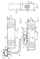
- an internal combustion engine air filter 1 is housed in a casing 2 connected by the connector 3 to the engine air intake manifold and provided with an air inlet port 4.
- the casing 2 is closed upperly by a cover 5 provided with a seal gasket 6, which clamps the filter 1 against the base surface of the casing 2 to allow the air drawn in by the effect of the vacuum in the engine intake manifold to pass only through the filtering surface of the filter.
- the indicator device consists of a substantially semicylindrical tubular duct 7, the flat base wall 8 of which is formed of a filter material and communicates by way of an outlet pipe 9 with the internal filter chamber 10 in which the vacuum produced by the engine intake exists.
- the upper wall 11 of the tubular duct 7 consists of transparent material able to allow the inner surface of the filter material wall 8 to be viewed.
- the end wall 12 is closed, whereas the opposite wall 13 comprises a hole 14 for the entry of air into the device, and in communication with the external environment.
- the intake air can pass through the wall 8 only in correspondence with the inner bore of the pipe 9, in the region indicated by 15 in the figure.
- This region is therefore subject to progressive deposition of solid particles in the same manner as the filtering surface of the filter 1 becomes clogged, these particles causing an alteration in the original colour of the inner surface of the wall 8, which can be viewed through the transparent wall 11 to provide a visual indication of the degree of soiling undergone by the said wall and by the filter 1.
- the transparent wall 11 is provided with a ring 16, most visible in Figure 3, formed from adhesive material, paints or the like, to reproduce the original appearance of the surface of the region 15 of the wall 8, or alternatively a scale of successive colorations assumed as clogging progresses, so as to allow comparison with the current state of the surface of the region 15.
- That surface of the wall 8 lying inside the duct can be provided with a coloration which reproduces intense colour lines or designs contrasting with the background colour, so that the progressive difficulty in distinguishing these chromatic motifs on the surface of the region 15 gives a clear indication of its state of clogging.
- a magnifying lens 17 can be located in the centre of the ring 16 to allow a magnified view of the area subject to soiling.
- the diameter of the hole 14 is chosen such that the quantity of air traversing the surface of the region 15 during a given time corresponds to the quantity of air traversing the filter 1 during the same period, so that the clogging of the passage region 15 of the wall 8 corresponds to analogous clogging of the filter 1.
- a slidable opaque cap 18 is provided on it, and is usually left over the wall 11 resting against the end wall 12, to be slid laterally into the position shown in Figure 1 when checking.
- the indicator device according to the invention can be mounted, as shown in Figure 1, by inserting the pipe 9 into a hole in the cover 5, by way of a sponge gasket 19 for sealing and vibration-damping purposes, or, as shown in Figure 2 in which the device according to the invention is illustrated in cross-section, the outlet pipe 9 can be connected by means of an extension pipe 20 to a point in the combustion air intake manifold downstream of the air filter, for example by connecting it into the engine oil vent gas draw-off pipe, which is under vacuum and opens into the combustion air intake manifold.
- the device can be fixed to the cover 5 of the casing housing the filter by means of a lug 21 of deformable material, to be inserted under the edge of the cover when this is closed after replacing the filter 1.
- the lens 17 and the coloured ring 16 which surrounds it can be disposed in such a position as to allow visual alignment between the lens and the region 15 from a position which is comfortable for checking purposes, for example it can be aligned with the region 15 along an observation line inclined at 45°.
Landscapes
- Chemical & Material Sciences (AREA)
- Engineering & Computer Science (AREA)
- Chemical Kinetics & Catalysis (AREA)
- Combustion & Propulsion (AREA)
- Mechanical Engineering (AREA)
- General Engineering & Computer Science (AREA)
- Filtering Of Dispersed Particles In Gases (AREA)
- Air-Conditioning For Vehicles (AREA)
Priority Applications (1)
| Application Number | Priority Date | Filing Date | Title |
|---|---|---|---|
| AT87830125T ATE66049T1 (de) | 1986-04-07 | 1987-04-03 | Vorrichtungen zur sichtbaren pruefung des verschmutzungsgrades eines luftfilters fuer fahrzeugmotoren. |
Applications Claiming Priority (2)
| Application Number | Priority Date | Filing Date | Title |
|---|---|---|---|
| IT3570486U | 1986-04-07 | ||
| IT8635704U IT207760Z2 (it) | 1986-04-07 | 1986-04-07 | Dispositivo di controllo visivo del grado di intasamento di un filtro per aria in motori per autoveicoli |
Publications (3)
| Publication Number | Publication Date |
|---|---|
| EP0241438A2 EP0241438A2 (en) | 1987-10-14 |
| EP0241438A3 EP0241438A3 (en) | 1988-09-21 |
| EP0241438B1 true EP0241438B1 (en) | 1991-08-07 |
Family
ID=11242542
Family Applications (1)
| Application Number | Title | Priority Date | Filing Date |
|---|---|---|---|
| EP87830125A Expired EP0241438B1 (en) | 1986-04-07 | 1987-04-03 | Device for visually checking the degree of clogging of an air filter in motor vehicle engines |
Country Status (5)
| Country | Link |
|---|---|
| US (1) | US4779456A (it) |
| EP (1) | EP0241438B1 (it) |
| AT (1) | ATE66049T1 (it) |
| DE (1) | DE3771904D1 (it) |
| IT (1) | IT207760Z2 (it) |
Families Citing this family (17)
| Publication number | Priority date | Publication date | Assignee | Title |
|---|---|---|---|---|
| US5042170A (en) * | 1990-09-04 | 1991-08-27 | Whirlpool Corporation | Lint collecting device |
| US5067253A (en) * | 1990-09-04 | 1991-11-26 | Whirlpool Corporation | Lint collecting device |
| US5670714A (en) * | 1996-03-27 | 1997-09-23 | Sorensen; Jens O. | Air-pollution reduction method and system for the interior of an automobile |
| US6110260A (en) * | 1998-07-14 | 2000-08-29 | 3M Innovative Properties Company | Filter having a change indicator |
| US6287456B1 (en) | 1998-10-30 | 2001-09-11 | Kimberly-Clark Worldwide, Inc. | Filtration system with filtrate volume indicator |
| JP2004036699A (ja) * | 2002-07-01 | 2004-02-05 | Honda Motor Co Ltd | フィルタ汚れ検出装置 |
| US6875249B2 (en) * | 2002-10-08 | 2005-04-05 | Donaldson Company, Inc. | Motor vehicle filter structure having visual indicator of useful life |
| CA2512303A1 (en) * | 2004-09-13 | 2006-03-13 | Nickolaj Hrebeniuk | View port window with optional illumination and alarm system |
| WO2010001381A1 (en) * | 2008-06-30 | 2010-01-07 | Association For Public Health Services | Air quality monitor |
| US8882735B2 (en) | 2008-12-16 | 2014-11-11 | Kimberly-Clark Worldwide, Inc. | Article with fluid-activated barriers |
| US8225729B2 (en) * | 2008-12-16 | 2012-07-24 | Kimberly-Clark Worldwide, Inc. | Three-dimensional wiping substrate and method therefor |
| US8507746B2 (en) | 2008-12-16 | 2013-08-13 | Kimberly-Clark Worldwide, Inc. | Leakage-signaling absorbent article |
| US7858055B2 (en) * | 2008-12-18 | 2010-12-28 | Kimberly-Clark Worldwide, Inc. | Moisture sensitive auxetic material |
| US8708988B2 (en) | 2010-12-03 | 2014-04-29 | Kimberly-Clark Worldwide, Inc. | Absorbent article configured for controlled deformation |
| KR102269043B1 (ko) * | 2014-08-05 | 2021-06-24 | 삼성전자주식회사 | 공기정화장치 |
| WO2019172736A2 (ko) * | 2019-07-09 | 2019-09-12 | 엘지전자 주식회사 | 필터의 교체시기 판단 방법 및 필터의 교체시기를 판단하는 공기 조화기 |
| CN115846099B (zh) * | 2023-02-22 | 2023-05-05 | 海安迪斯凯瑞探测仪器有限公司 | 一种基于喷漆房的废气处理设备 |
Family Cites Families (10)
| Publication number | Priority date | Publication date | Assignee | Title |
|---|---|---|---|---|
| US2655894A (en) * | 1951-04-21 | 1953-10-20 | Fram Corp | Gas filter indicator |
| US3060527A (en) * | 1960-02-03 | 1962-10-30 | Truscon Steel Company Of Canad | Split window construction |
| US3143997A (en) * | 1962-10-18 | 1964-08-11 | Gen Motors Corp | Filter capacity indicator |
| US3246624A (en) * | 1965-02-05 | 1966-04-19 | Novo Ind Corp | Pressure indicating device |
| US3591945A (en) * | 1969-03-27 | 1971-07-13 | Charles Eisel | Engine air filter unit |
| US4162660A (en) * | 1978-06-29 | 1979-07-31 | Albertson Robert V | Dirty air filter indicator |
| DE3107974C2 (de) * | 1981-03-03 | 1984-09-27 | Knecht Filterwerke Gmbh, 7000 Stuttgart | Differenzdruck-Anzeigevorrichtung für Luftfilter |
| JPS5849517A (ja) * | 1981-09-19 | 1983-03-23 | Honda Motor Co Ltd | 自動二輪車 |
| US4561395A (en) * | 1984-06-25 | 1985-12-31 | Mcmullen Tod | Auxiliary oil filtration system |
| US4548166A (en) * | 1985-01-07 | 1985-10-22 | General Motors Corporation | Engine air cleaner and duct arrangement |
-
1986
- 1986-04-07 IT IT8635704U patent/IT207760Z2/it active
-
1987
- 1987-04-03 AT AT87830125T patent/ATE66049T1/de active
- 1987-04-03 DE DE87830125T patent/DE3771904D1/de not_active Expired - Fee Related
- 1987-04-03 EP EP87830125A patent/EP0241438B1/en not_active Expired
- 1987-04-06 US US07/034,927 patent/US4779456A/en not_active Expired - Fee Related
Also Published As
| Publication number | Publication date |
|---|---|
| US4779456A (en) | 1988-10-25 |
| DE3771904D1 (en) | 1991-09-12 |
| ATE66049T1 (de) | 1991-08-15 |
| EP0241438A2 (en) | 1987-10-14 |
| IT207760Z2 (it) | 1988-02-15 |
| IT8635704V0 (it) | 1986-04-07 |
| EP0241438A3 (en) | 1988-09-21 |
Similar Documents
| Publication | Publication Date | Title |
|---|---|---|
| EP0241438B1 (en) | Device for visually checking the degree of clogging of an air filter in motor vehicle engines | |
| US4440555A (en) | Engine compartment and air cleaner | |
| EP0200688A1 (en) | Member for indicating clogging of the air intake filter, particularly for motor vehicle engines | |
| US4787922A (en) | Filter apparatus | |
| US6167862B1 (en) | Air cleaner system | |
| JPH04503234A (ja) | 二重機能エアフィルタ | |
| JP3589840B2 (ja) | 内燃機関の吸気装置 | |
| EP0894971B1 (en) | Combination air cleaner fluid reservoir | |
| US2655894A (en) | Gas filter indicator | |
| GB2162087A (en) | Air filter | |
| US4162660A (en) | Dirty air filter indicator | |
| US20040011010A1 (en) | Panel type air filter element with integral baffle | |
| US5676115A (en) | Work apparatus having an internal combustion engine | |
| JPH0581738B2 (it) | ||
| US6293981B1 (en) | Arrangement of an air filter and a membrane carburetor | |
| AU734672B2 (en) | Indicator arrangement for air cleaner systems and methods thereof | |
| IL105010A (en) | Device for attaching a fan to a face mask filter | |
| WO1990003836A1 (en) | Disposable air filter | |
| CN2287507Y (zh) | 带透视镜的过滤器 | |
| GB2320690A (en) | Self-cleaning air filter | |
| US3194056A (en) | Permeability testing method and apparatus | |
| CN213119409U (zh) | 智能空气净化装置 | |
| CA1044080A (en) | Filter malfunction detector | |
| CN212803427U (zh) | 一种沙漠环境下使用空气滤清器 | |
| KR0138844Y1 (ko) | 스로틀 바디의 이물질 유입 방지장치 |
Legal Events
| Date | Code | Title | Description |
|---|---|---|---|
| PUAI | Public reference made under article 153(3) epc to a published international application that has entered the european phase |
Free format text: ORIGINAL CODE: 0009012 |
|
| AK | Designated contracting states |
Kind code of ref document: A2 Designated state(s): AT BE CH DE ES FR GB GR IT LI LU NL SE |
|
| PUAL | Search report despatched |
Free format text: ORIGINAL CODE: 0009013 |
|
| AK | Designated contracting states |
Kind code of ref document: A3 Designated state(s): AT BE CH DE ES FR GB GR IT LI LU NL SE |
|
| 17P | Request for examination filed |
Effective date: 19881121 |
|
| 17Q | First examination report despatched |
Effective date: 19890323 |
|
| GRAA | (expected) grant |
Free format text: ORIGINAL CODE: 0009210 |
|
| AK | Designated contracting states |
Kind code of ref document: B1 Designated state(s): AT BE CH DE ES FR GB GR IT LI LU NL SE |
|
| PG25 | Lapsed in a contracting state [announced via postgrant information from national office to epo] |
Ref country code: SE Effective date: 19910807 Ref country code: NL Effective date: 19910807 Ref country code: LI Effective date: 19910807 Ref country code: GR Free format text: LAPSE BECAUSE OF FAILURE TO SUBMIT A TRANSLATION OF THE DESCRIPTION OR TO PAY THE FEE WITHIN THE PRESCRIBED TIME-LIMIT Effective date: 19910807 Ref country code: CH Effective date: 19910807 Ref country code: BE Effective date: 19910807 Ref country code: AT Effective date: 19910807 |
|
| REF | Corresponds to: |
Ref document number: 66049 Country of ref document: AT Date of ref document: 19910815 Kind code of ref document: T |
|
| REF | Corresponds to: |
Ref document number: 3771904 Country of ref document: DE Date of ref document: 19910912 |
|
| ITF | It: translation for a ep patent filed |
Owner name: ST. DR. CAVATTONI ING. A. RAIMONDI |
|
| ET | Fr: translation filed | ||
| REG | Reference to a national code |
Ref country code: CH Ref legal event code: PL |
|
| PG25 | Lapsed in a contracting state [announced via postgrant information from national office to epo] |
Ref country code: ES Free format text: LAPSE BECAUSE OF FAILURE TO SUBMIT A TRANSLATION OF THE DESCRIPTION OR TO PAY THE FEE WITHIN THE PRESCRIBED TIME-LIMIT Effective date: 19911118 |
|
| NLV1 | Nl: lapsed or annulled due to failure to fulfill the requirements of art. 29p and 29m of the patents act | ||
| PG25 | Lapsed in a contracting state [announced via postgrant information from national office to epo] |
Ref country code: LU Free format text: LAPSE BECAUSE OF NON-PAYMENT OF DUE FEES Effective date: 19920430 |
|
| PLBE | No opposition filed within time limit |
Free format text: ORIGINAL CODE: 0009261 |
|
| STAA | Information on the status of an ep patent application or granted ep patent |
Free format text: STATUS: NO OPPOSITION FILED WITHIN TIME LIMIT |
|
| 26N | No opposition filed | ||
| PGFP | Annual fee paid to national office [announced via postgrant information from national office to epo] |
Ref country code: FR Payment date: 19940329 Year of fee payment: 8 |
|
| PGFP | Annual fee paid to national office [announced via postgrant information from national office to epo] |
Ref country code: DE Payment date: 19940331 Year of fee payment: 8 |
|
| PGFP | Annual fee paid to national office [announced via postgrant information from national office to epo] |
Ref country code: GB Payment date: 19950403 Year of fee payment: 9 |
|
| PG25 | Lapsed in a contracting state [announced via postgrant information from national office to epo] |
Ref country code: FR Effective date: 19951229 |
|
| PG25 | Lapsed in a contracting state [announced via postgrant information from national office to epo] |
Ref country code: DE Effective date: 19960103 |
|
| REG | Reference to a national code |
Ref country code: FR Ref legal event code: ST |
|
| PG25 | Lapsed in a contracting state [announced via postgrant information from national office to epo] |
Ref country code: GB Effective date: 19960403 |
|
| GBPC | Gb: european patent ceased through non-payment of renewal fee |
Effective date: 19960403 |
|
| PG25 | Lapsed in a contracting state [announced via postgrant information from national office to epo] |
Ref country code: IT Free format text: LAPSE BECAUSE OF NON-PAYMENT OF DUE FEES Effective date: 20050403 |