EP0894971B1 - Combination air cleaner fluid reservoir - Google Patents
Combination air cleaner fluid reservoir Download PDFInfo
- Publication number
- EP0894971B1 EP0894971B1 EP98305889A EP98305889A EP0894971B1 EP 0894971 B1 EP0894971 B1 EP 0894971B1 EP 98305889 A EP98305889 A EP 98305889A EP 98305889 A EP98305889 A EP 98305889A EP 0894971 B1 EP0894971 B1 EP 0894971B1
- Authority
- EP
- European Patent Office
- Prior art keywords
- air
- housing
- induction device
- chamber
- air induction
- Prior art date
- Legal status (The legal status is an assumption and is not a legal conclusion. Google has not performed a legal analysis and makes no representation as to the accuracy of the status listed.)
- Expired - Lifetime
Links
- 239000012530 fluid Substances 0.000 title claims description 26
- 239000003570 air Substances 0.000 claims description 80
- 230000006698 induction Effects 0.000 claims description 21
- 239000012080 ambient air Substances 0.000 claims description 8
- 239000007788 liquid Substances 0.000 claims description 7
- 238000002485 combustion reaction Methods 0.000 description 8
- 239000000945 filler Substances 0.000 description 6
- 238000001914 filtration Methods 0.000 description 6
- 238000004140 cleaning Methods 0.000 description 3
- 238000007789 sealing Methods 0.000 description 3
- 239000007789 gas Substances 0.000 description 2
- 230000003993 interaction Effects 0.000 description 2
- 230000004888 barrier function Effects 0.000 description 1
- 239000000428 dust Substances 0.000 description 1
- 238000005516 engineering process Methods 0.000 description 1
- 239000000446 fuel Substances 0.000 description 1
- 239000003517 fume Substances 0.000 description 1
- 230000030279 gene silencing Effects 0.000 description 1
- 239000002245 particle Substances 0.000 description 1
- 230000002093 peripheral effect Effects 0.000 description 1
- 239000011347 resin Substances 0.000 description 1
- 229920005989 resin Polymers 0.000 description 1
Images


Classifications
-
- F—MECHANICAL ENGINEERING; LIGHTING; HEATING; WEAPONS; BLASTING
- F02—COMBUSTION ENGINES; HOT-GAS OR COMBUSTION-PRODUCT ENGINE PLANTS
- F02M—SUPPLYING COMBUSTION ENGINES IN GENERAL WITH COMBUSTIBLE MIXTURES OR CONSTITUENTS THEREOF
- F02M35/00—Combustion-air cleaners, air intakes, intake silencers, or induction systems specially adapted for, or arranged on, internal-combustion engines
- F02M35/14—Combined air cleaners and silencers
-
- F—MECHANICAL ENGINEERING; LIGHTING; HEATING; WEAPONS; BLASTING
- F02—COMBUSTION ENGINES; HOT-GAS OR COMBUSTION-PRODUCT ENGINE PLANTS
- F02M—SUPPLYING COMBUSTION ENGINES IN GENERAL WITH COMBUSTIBLE MIXTURES OR CONSTITUENTS THEREOF
- F02M35/00—Combustion-air cleaners, air intakes, intake silencers, or induction systems specially adapted for, or arranged on, internal-combustion engines
- F02M35/12—Intake silencers ; Sound modulation, transmission or amplification
- F02M35/1255—Intake silencers ; Sound modulation, transmission or amplification using resonance
- F02M35/1266—Intake silencers ; Sound modulation, transmission or amplification using resonance comprising multiple chambers or compartments
Definitions
- This invention relates to air handling systems, in particular, for filtering ambient air to be fed to a device requiring a source of clean air.
- the invention relates to providing filtered air to internal combustion engines.
- the induction passage of the engine includes a filter.
- Some type of housing must be made which supports the filter element and which guides air to force it to pass through the filtration element and then to duct the filtered air to the engine intake passages.
- Fluid may be required to clean a front windshield or a rear window or any other surface through which the operator may wish to have an unobstructed view.
- vehicles are equipped with a housing which comprises a fluid storage chamber.
- the storage chamber may have a sump or other means to accommodate a fluid pump. Fluid may then be pumped from the storage chamber to nozzles or other like devices around the vehicle to assist in cleaning viewing surfaces.
- a vehicle is shown in WO-A-87/06547.
- the fluid storage chamber has been independent of any ambient air flow chambers.
- ducting is provided to the air flow chamber and the air flow chamber is supported on the engine or the vehicle as needed.
- the fluid reservoir chamber is also located on the vehicle wherever space permits and means are provided to mount the fluid reservoir chamber on either the engine or the vehicle as desired.
- the filter elements for such vehicles require replacement from time to time and thus the housing defining the flow paths for the ambient air through the filter element must be openable in some fashion to permit replacement or cleaning of the filtration element.
- the air flow chamber is adapted to contain a filter element.
- the combined unit has an inlet for ambient air and an air outlet for filtered air.
- the air flow chamber communicates with the acoustic resonance chamber for modifying acoustic characteristics.
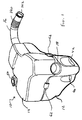
- the air induction device is indicated generally at 10 and is shown in Figure 1.
- the air induction device comprises a first housing 12 and a second housing 14. Filtered air is delivered from the air induction device by means of clean air outlet duct 16 to the internal combustion engine or other source. Ambient air is drawn from the surrounding air and inducted into the air induction device through the intake snorkel 18.
- the first housing 12 is illustrated in Figure 2.
- the housing 12 defines a closed liquid storage chamber 20.
- the chamber 20 is visible in the cross-sectional view in Figure 3.
- the housing 12 defines an inlet passage 22 and an outlet passage 24.
- Each of the inlet passage 22 and the outlet passage 24 are substantially semi-cylindrical, although the exact configuration is a matter of choice.
- the inlet passage 22 and the outlet passage 24 both open towards the substantially planar face 26 of the housing 12.
- the housing 12 also defines a recessed, substantially semi-cylindrical surface 28A.
- the surface 28A defines in part, an air flow chamber 128.
- the surface 28A comprises a series of lands to position and seal a filter element to be discussed later.
- the filter positioning and sealing arrangements comprise the substantially semi-annular wall 30, the substantially semi-cylindrical wall 32 and the substantially semi-annular wall 34.
- a similar set of walls is partially visible in Figure 2 and has been marked 36. It will be appreciated that the surfaces at 36 are mirror images of those shown at 30, 32 and 34.
- the semi-cylindrical surface 32 and its mirror image at 36 serve to locate the filter which will have cylindrical walls at either end.
- the length and diameter of the surface 28A is designed to accommodate the particular style of filter required.
- the housing 12 may also conveniently define fluid pump locating elements.
- a recess 40 is sufficiently large to accommodate a single fluid pump.
- the similar recess 42 is large enough to accommodate two such fluid pumps.
- three fluid delivery pumps can be accommodated by the device.
- Each of the fluid pumps will have an aperture communicating with the interior of the fluid storage chamber 20.
- the pumps which are not shown in Figure 2, but which may be located in the recesses 40 and 42 and can then be used to deliver fluid to one or more purposes as desired by the vehicle operator.
- the housing 12 In order to add fluid to the chamber 20 from time to time the housing 12 defines an upstanding filler neck 46. Mounted on top of the filler neck there is an aperture 48 which is closed by a cover 50. In order to add fluid to the chamber, the cover 50 is removed and the desired fluid is poured through the aperture 48 into the chamber 20.
- the housing 12 also comprises a hinge 60A.
- the hinge 60A is located on the surface 26 adjacent to the filler neck 46.
- the housing 12 also defines two latch components 62A and 64A. The function of the hinge 60A and the latch components 62A and 64A will be discussed below.
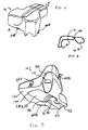
- the second housing 14 is illustrated in Figures 4, 5 and 6.
- the second housing 14 defines an acoustic resonance chamber.
- the acoustic resonance chamber comprises two separated chambers 70A and 70B.
- the two separate acoustic resonance chambers are visible in Figure 6.
- the two separate chambers 70A and 70B are separated one from another by pinching the walls of the housing 14 together at 72 as illustrated in Figure 6.
- the housing 14 defines an inlet passage 90 and an outlet passage 92.
- the inlet passage 90 and the outlet passage 92 are each substantially semi-cylindrical in shape and have essentially the same dimensions of length and diameter respectively as the passages 22 and 24 in first housing 12.
- the second housing 14 also defines a recessed semi-cylindrical surface 28B.
- the surface 28B is similar in size and configuration to the surface 28A of housing 12.
- the surface 28B comprises a substantially semi-annular wall 94, a substantially semi-cylindrical wall 96 and a substantially semi-annular wall 98.
- the interaction of the walls 94, 96 and 98 is the same as the walls 30, 32 and 34 of the housing 12.
- the housing 14 also comprises similar arrangement of walls indicated generally in Figure 5 by the numeral 100. At 100 there are three walls which are the mirror images of the walls 94, 96 and 98. These walls also serve to position and seal a replaceable filter element.
- the housing 14 also defines a hinge element 60B and a pair of latch components 62B and 64B.
- the housing 14 includes a first port 110 in the surface of the inlet passage 90.
- the first port 110 communicates with the acoustics resonance chamber 70A.
- the outlet passage 92 of the housing 14 also includes a second port 112.
- the port 112 communicates with the acoustic resonance chamber 70B.
- the second housing 14 has a substantially planar surface 120.
- the second housing 14 is surmounted on the first housing 12. With the two housings located adjacent one another as shown in Figure 1, then the surface 120 will lie on and be supported by the surface 26 of the first housing 12.
- the inlet passage 22 and the inlet passage 90 combine to form a substantially closed cylindrical passage.
- the outlet passage 24 and the outlet passage 92 combine to form a substantially closed cylindrical passage.
- the surface 28B of the housing 14 and the surface 28A of the housing 12 combine to form a substantially closed cylindrical air flow chamber which is adapted to contain a filter element.
- the hinge means 60A of the housing 12 and the hinge means 60B of the housing 14 are hingedly interconnected to provide a pivoting axis along the hinge members 60A and 60B.
- the surfaces 120 and 26 will be in contact.
- the latch components 62A and 62B will be adjacent one another as will the latch components 64A and 64B.
- FIG 9 illustrates a cartridge filter element 122.
- the cartridge element may be of any size and configuration as desired. Most conveniently this may be a cylindrical element of paper such as a so-called dry filter.
- the filter element 122 is configured so as to be sealingly received within the walls 30, 32, 34, 94, 96, 98 as shown in Figures 2 and 5.
- the filter element has two ends which are substantially identical. The other end of the filter element is received in the walls indicated generally at 36 in Figure 2 and 100 in Figure 5 so that the filter is sealingly received within the portion of the air flow chamber 128 defined by surfaces 28A and 28B.
- FIG 7 illustrates the clean air outlet duct 16.
- the clean air outlet duct comprises a substantially tubular portion having a bellows section 140.
- the clean air outlet duct has an aperture 142 at the outlet end of the outlet duct.
- the duct 16 may be attached to the engine components to feed filtered air directly to the engine.
- the bellows section 140 facilitates aligning the outlet 142 with the engine.
- the inlet end 144 of the clean air outlet duct 16 includes a substantially cylindrical seal 146.
- the seal 146 of the outlet duct 16 communicates with the interior surface of the filter element 122 to provide a gas tight seal.
- the clean air outlet duct 16 also comprises an upstanding collar 148 having an aperture 150 and a substantially cylindrical seal 152.
- the upstanding collar 148 is received within the aperture 112 visible in Figure 5.
- the seal 152 seals about the periphery of the aperture 112 to comprise a gas tight seal.
- FIG 8 illustrates the intake snorkel 18.
- the intake snorkel 18 comprises a horn-shaped inlet 160 and a substantially cylindrical tubular passage 162.
- the upstanding collar 164 is received within the aperture 110.
- the air flow chamber 128 includes the intake snorkel 18, the surfaces 28A and 28B and the clean air outlet duct 16.
- the housing 12 comprises mounting means 180 illustrated in Figure 2 in order that the housing 12 may be conveniently mounted to a support portion of the vehicle in which the air induction device is to be used.
- the housing 14 comprises a relieved portion at the peripheral edge. That portion curves about the upstanding filler neck 46 of the housing 12.
- the device as illustrated in Figure 1 functions as follows.
- the housing 12 will be affixed to the vehicle in some suitable location. The location is chosen so that the inlet horn 160 of the intake snorkel 18 has access to free flowing air.
- the air drawn into the internal combustion engine creates a vacuum pressure in the clean air outlet duct 16. That vacuum pressure will draw air into the intake snorkel 18.
- As the air flows along the intake snorkel it will be delivered from the intake snorkel 18 to the exterior of the portion of the air flow chamber 128, formed by the surfaces 28A and 28B.
- the air can flow circumferentially around the entire surface formed by the surfaces 28A and 28B exterior to the filter element 122.
- the air can then flow through the filter element 122 radially inwardly whereupon it is filtered.
- the filtered air is then drawn into the clean air outlet duct 16.
- the vacuum pressure created by the engine is sealed by means of seal 146 with the interior of the filter element 122. Accordingly, even if some air does pass along the intersection of surfaces 120 and 26, that air cannot reach the engine intake passage without travelling through the filter element 122. In order to ensure that this occurs the filter element 122 must be sealed at either end. This is accomplished by the interaction of walls 30, 32, 34 of the first housing 12 and similar walls 94, 96, 98 of the housing 14. Similar sealing occurs at the areas indicated generally by the numbers 36 and 100.
- acoustics resonance chambers may be designed to attenuate the noise significantly. The most effective attenuation of noise can be achieved by two separate chambers located on either side of the filtration barrier.
- the intake snorkel 18 communicates with the first acoustic resonance chamber 70A by means of the collar 164.
- the clean air outlet duct 16 communicates with the acoustics resonance chamber 70B by means of the upstanding collar 148 and its seal 152.
- the size, configuration and location of the acoustic chamber can be arranged to meet the design requirements of the designer. Those features are well understood by those familiar with air intake silencing technology.
- the filter element 122 will require replacement from time to time on a regular basis.
- the latch elements 62 and 64 are disengaged.
- the housing 14 is pivoted about the hinge 60. With the housing 12 and 14 then in the open position, the filter element 122 may be easily removed from the device and replaced with a clean element.
- the upstanding filler neck 46 is substantially long enough to provide easy access to the filler aperture 48. Accordingly, when the two housings are held together by the latch components 62 and 64, the cap 50 and the aperture 48 of the liquid storage chamber remain available for access. Accordingly, when it is desired to add fluid to the fluid storage chamber, it is necessary only to remove the cap 50 and pour fluid into the chamber 20.
- the first housing 12 defining the liquid storage chamber is vertically below the second housing 14 defining the acoustic resonance chamber.
- the configuration of the parts may be altered as desired by the designer.
- the chambers need not be one on top of the other, but could be arranged side by side or in other configuration as desired. It is believed however that the configuration illustrated in this embodiment is the most desirable, providing for efficient location and flow of liquid to pumps which may be placed in the recesses 40 and 42 as well as convenient access to the replaceable filter element.
- the housings 12 and 14 are essentially hollow members which may have any configuration desirable.
- the constraints on the configuration will involve not only the acoustic resonance attenuation but also the physical limitations within the vehicle where the device is to be located.
- Relatively complicated hollow shapes of this type may be manufactured easily from blow molded parts.
- consideration must be given to the flow of the blow moldable resin.
- the surfaces 120 and 26 are not essentially planar surfaces.
- Other shapes may also be appropriate depending upon the many considerations referred to above. Even if the surfaces 26 and 120 are essentially planar surfaces, it is by no means required that those surfaces be presented in a substantially horizontal direction.
Landscapes
- Engineering & Computer Science (AREA)
- Chemical & Material Sciences (AREA)
- Combustion & Propulsion (AREA)
- Mechanical Engineering (AREA)
- General Engineering & Computer Science (AREA)
- Filtering Of Dispersed Particles In Gases (AREA)
- Cooling, Air Intake And Gas Exhaust, And Fuel Tank Arrangements In Propulsion Units (AREA)
Description
- This invention relates to air handling systems, in particular, for filtering ambient air to be fed to a device requiring a source of clean air. In particular, the invention relates to providing filtered air to internal combustion engines.
- Many vehicles are powered by internal combustion engines. Internal combustion engines require a source of air normally for combustion of the fuel involved. The combustion air is drawn from the ambient air surrounding the vehicle. The ambient air may contain dust or fume particles which if ingested into the engine would damage such an engine or reduce its useful life. Typically, therefore the induction passage of the engine includes a filter. Some type of housing must be made which supports the filter element and which guides air to force it to pass through the filtration element and then to duct the filtered air to the engine intake passages.
- It is also common in vehicles, particularly vehicles which travel on roads, to provide a source of fluid to be used in cleaning viewing surfaces, principally the windshield of the vehicle. Fluid may be required to clean a front windshield or a rear window or any other surface through which the operator may wish to have an unobstructed view. Typically, vehicles are equipped with a housing which comprises a fluid storage chamber. The storage chamber may have a sump or other means to accommodate a fluid pump. Fluid may then be pumped from the storage chamber to nozzles or other like devices around the vehicle to assist in cleaning viewing surfaces. Such a vehicle is shown in WO-A-87/06547.
- Heretofore the fluid storage chamber has been independent of any ambient air flow chambers. Typically ducting is provided to the air flow chamber and the air flow chamber is supported on the engine or the vehicle as needed. Additionally, the fluid reservoir chamber is also located on the vehicle wherever space permits and means are provided to mount the fluid reservoir chamber on either the engine or the vehicle as desired.
- Typically the filter elements for such vehicles require replacement from time to time and thus the housing defining the flow paths for the ambient air through the filter element must be openable in some fashion to permit replacement or cleaning of the filtration element.
- It has been recognized that it would be cost effective to provide a combined unit which serves the purpose of providing a fluid storage chamber and which also provides suitable air induction system including the location of a replaceable filtration element together with suitable flow passages. In accordance with this invention an air induction device for use with a vehicle requiring a source of filtered air comprises a first housing defining a liquid storage chamber and a second housing defining an acoustic resonance chamber, the first and second housings define therebetween, at least in part, an air flow chamber. The air flow chamber is adapted to contain a filter element. The combined unit has an inlet for ambient air and an air outlet for filtered air. The air flow chamber communicates with the acoustic resonance chamber for modifying acoustic characteristics.
- The invention will be better understood in connection with a review of the attached drawings which illustrate a preferred embodiment of the invention, and in which:
- Figure 1 is a perspective view of preferred embodiment of the air induction device in accordance with the invention;
- Figure 2 is a perspective view of the first housing of the device illustrated in Figure 1;
- Figure 3 is a cross-section through the housing of Figure 2 taken along the plane 3-3 identified in Figure 2;
- Figure 4 is a perspective view of the second housing of the device shown in Figure 1;
- Figure 5 is a bottom view of the housing shown in Figure 4;
- Figure 6 is a cross-sectional view through the housing of Figure 4 along the plane identified by the numerals 6-6 in Figure 4;
- Figure 7 illustrates a clean air outlet duct of the device of Figure 1;
- Figure 8 is a perspective view of the intake snorkel of the device of Figure 1;
- Figure 9 is a filter element for use in association with the device shown in Figure 1;
-
- The air induction device is indicated generally at 10 and is shown in Figure 1. The air induction device comprises a
first housing 12 and asecond housing 14. Filtered air is delivered from the air induction device by means of cleanair outlet duct 16 to the internal combustion engine or other source. Ambient air is drawn from the surrounding air and inducted into the air induction device through theintake snorkel 18. - The
first housing 12 is illustrated in Figure 2. Thehousing 12 defines a closedliquid storage chamber 20. Thechamber 20 is visible in the cross-sectional view in Figure 3. Thehousing 12 defines an inlet passage 22 and anoutlet passage 24. Each of the inlet passage 22 and theoutlet passage 24 are substantially semi-cylindrical, although the exact configuration is a matter of choice. The inlet passage 22 and theoutlet passage 24 both open towards the substantiallyplanar face 26 of thehousing 12. Thehousing 12 also defines a recessed, substantially semi-cylindrical surface 28A. The surface 28A defines in part, an air flow chamber 128. - The surface 28A comprises a series of lands to position and seal a filter element to be discussed later. The filter positioning and sealing arrangements comprise the substantially
semi-annular wall 30, the substantiallysemi-cylindrical wall 32 and the substantiallysemi-annular wall 34. A similar set of walls is partially visible in Figure 2 and has been marked 36. It will be appreciated that the surfaces at 36 are mirror images of those shown at 30, 32 and 34. Thesemi-cylindrical surface 32 and its mirror image at 36 serve to locate the filter which will have cylindrical walls at either end. The length and diameter of the surface 28A is designed to accommodate the particular style of filter required. - The
housing 12 may also conveniently define fluid pump locating elements. Arecess 40 is sufficiently large to accommodate a single fluid pump. Thesimilar recess 42 is large enough to accommodate two such fluid pumps. Thus, in the device shown in Figure 3, three fluid delivery pumps can be accommodated by the device. Each of the fluid pumps will have an aperture communicating with the interior of thefluid storage chamber 20. The pumps which are not shown in Figure 2, but which may be located in therecesses - In order to add fluid to the
chamber 20 from time to time thehousing 12 defines anupstanding filler neck 46. Mounted on top of the filler neck there is anaperture 48 which is closed by a cover 50. In order to add fluid to the chamber, the cover 50 is removed and the desired fluid is poured through theaperture 48 into thechamber 20. - The
housing 12 also comprises a hinge 60A. The hinge 60A is located on thesurface 26 adjacent to thefiller neck 46. Thehousing 12 also defines twolatch components 62A and 64A. The function of the hinge 60A and thelatch components 62A and 64A will be discussed below. - The
second housing 14 is illustrated in Figures 4, 5 and 6. Thesecond housing 14 defines an acoustic resonance chamber. In this case the acoustic resonance chamber comprises two separated chambers 70A and 70B. The two separate acoustic resonance chambers are visible in Figure 6. The two separate chambers 70A and 70B are separated one from another by pinching the walls of thehousing 14 together at 72 as illustrated in Figure 6. - With reference to Figure 5 which illustrates the bottom of the device shown in Figure 4, it will be observed that the
housing 14 defines aninlet passage 90 and anoutlet passage 92. Theinlet passage 90 and theoutlet passage 92 are each substantially semi-cylindrical in shape and have essentially the same dimensions of length and diameter respectively as thepassages 22 and 24 infirst housing 12. Thesecond housing 14 also defines a recessed semi-cylindrical surface 28B. The surface 28B is similar in size and configuration to the surface 28A ofhousing 12. In order to further position the filter element the surface 28B comprises a substantiallysemi-annular wall 94, a substantiallysemi-cylindrical wall 96 and a substantiallysemi-annular wall 98. The interaction of thewalls walls housing 12. Thehousing 14 also comprises similar arrangement of walls indicated generally in Figure 5 by the numeral 100. At 100 there are three walls which are the mirror images of thewalls - The
housing 14 also defines ahinge element 60B and a pair of latch components 62B and 64B. - From reference to Figure 5 it will be noted that the
housing 14 includes afirst port 110 in the surface of theinlet passage 90. Thefirst port 110 communicates with the acoustics resonance chamber 70A. Theoutlet passage 92 of thehousing 14 also includes asecond port 112. Theport 112 communicates with the acoustic resonance chamber 70B. - The
second housing 14 has a substantially planar surface 120. - In use, the
second housing 14 is surmounted on thefirst housing 12. With the two housings located adjacent one another as shown in Figure 1, then the surface 120 will lie on and be supported by thesurface 26 of thefirst housing 12. When in that configuration and location, the inlet passage 22 and theinlet passage 90 combine to form a substantially closed cylindrical passage. Similarly, theoutlet passage 24 and theoutlet passage 92 combine to form a substantially closed cylindrical passage. The surface 28B of thehousing 14 and the surface 28A of thehousing 12 combine to form a substantially closed cylindrical air flow chamber which is adapted to contain a filter element. - In order to keep the
housing 12 and thehousing 14 attached together and located as indicated above, the hinge means 60A of thehousing 12 and the hinge means 60B of thehousing 14 are hingedly interconnected to provide a pivoting axis along thehinge members 60A and 60B. When the first andsecond housings surfaces 120 and 26 will be in contact. When those surfaces are in contact with one another, thelatch components 62A and 62B will be adjacent one another as will the latch components 64A and 64B. By connecting the latch components together the housings form a single integral unit. When in the closed position,housing latch components housing 14 pivoted relative tohousing 12 about the axis of hinge 60. - Figure 9 illustrates a
cartridge filter element 122. The cartridge element may be of any size and configuration as desired. Most conveniently this may be a cylindrical element of paper such as a so-called dry filter. Thefilter element 122 is configured so as to be sealingly received within thewalls - Figure 7 illustrates the clean
air outlet duct 16. The clean air outlet duct comprises a substantially tubular portion having abellows section 140. The clean air outlet duct has anaperture 142 at the outlet end of the outlet duct. Theduct 16 may be attached to the engine components to feed filtered air directly to the engine. Thebellows section 140 facilitates aligning theoutlet 142 with the engine. Theinlet end 144 of the cleanair outlet duct 16 includes a substantiallycylindrical seal 146. Theseal 146 of theoutlet duct 16 communicates with the interior surface of thefilter element 122 to provide a gas tight seal. The cleanair outlet duct 16 also comprises an upstanding collar 148 having an aperture 150 and a substantially cylindrical seal 152. The upstanding collar 148 is received within theaperture 112 visible in Figure 5. The seal 152 seals about the periphery of theaperture 112 to comprise a gas tight seal. - Figure 8 illustrates the
intake snorkel 18. Theintake snorkel 18 comprises a horn-shapedinlet 160 and a substantially cylindrical tubular passage 162. There is an upstandingcylindrical collar 164 having anaperture 166 and a substantiallycylindrical seal 168. Theupstanding collar 164 is received within theaperture 110. When thehousings passages passages 22 and 90. Thus, in this preferred embodiment, the air flow chamber 128 includes theintake snorkel 18, the surfaces 28A and 28B and the cleanair outlet duct 16. - The
housing 12 comprises mounting means 180 illustrated in Figure 2 in order that thehousing 12 may be conveniently mounted to a support portion of the vehicle in which the air induction device is to be used. - With reference to Figures 2 and 5, it will be observed that the
housing 14 comprises a relieved portion at the peripheral edge. That portion curves about theupstanding filler neck 46 of thehousing 12. - The device as illustrated in Figure 1 functions as follows. The
housing 12 will be affixed to the vehicle in some suitable location. The location is chosen so that theinlet horn 160 of theintake snorkel 18 has access to free flowing air. The air drawn into the internal combustion engine creates a vacuum pressure in the cleanair outlet duct 16. That vacuum pressure will draw air into theintake snorkel 18. As the air flows along the intake snorkel it will be delivered from theintake snorkel 18 to the exterior of the portion of the air flow chamber 128, formed by the surfaces 28A and 28B. The air can flow circumferentially around the entire surface formed by the surfaces 28A and 28B exterior to thefilter element 122. The air can then flow through thefilter element 122 radially inwardly whereupon it is filtered. The filtered air is then drawn into the cleanair outlet duct 16. - The two surfaces, 120 of
housing housing 12, need not be in sealing engagement in this embodiment. The vacuum pressure created by the engine is sealed by means ofseal 146 with the interior of thefilter element 122. Accordingly, even if some air does pass along the intersection ofsurfaces 120 and 26, that air cannot reach the engine intake passage without travelling through thefilter element 122. In order to ensure that this occurs thefilter element 122 must be sealed at either end. This is accomplished by the interaction ofwalls first housing 12 andsimilar walls housing 14. Similar sealing occurs at the areas indicated generally by thenumbers 36 and 100. - It is well-known to those familiar with designing internal combustion engines that substantial noise is created in the air intake passageway. It is also well understood by those skilled in this art that acoustics resonance chambers may be designed to attenuate the noise significantly. The most effective attenuation of noise can be achieved by two separate chambers located on either side of the filtration barrier. Thus, the
intake snorkel 18 communicates with the first acoustic resonance chamber 70A by means of thecollar 164. Similarly, the cleanair outlet duct 16 communicates with the acoustics resonance chamber 70B by means of the upstanding collar 148 and its seal 152. The size, configuration and location of the acoustic chamber can be arranged to meet the design requirements of the designer. Those features are well understood by those familiar with air intake silencing technology. - The
filter element 122 will require replacement from time to time on a regular basis. When it is desired to replace the filter element thelatch elements housing 14 is pivoted about the hinge 60. With thehousing filter element 122 may be easily removed from the device and replaced with a clean element. - With reference to Figure 1 it will be observed that the
upstanding filler neck 46 is substantially long enough to provide easy access to thefiller aperture 48. Accordingly, when the two housings are held together by thelatch components aperture 48 of the liquid storage chamber remain available for access. Accordingly, when it is desired to add fluid to the fluid storage chamber, it is necessary only to remove the cap 50 and pour fluid into thechamber 20. - As shown and discussed in this preferred embodiment, the
first housing 12 defining the liquid storage chamber is vertically below thesecond housing 14 defining the acoustic resonance chamber. However, the configuration of the parts may be altered as desired by the designer. The chambers need not be one on top of the other, but could be arranged side by side or in other configuration as desired. It is believed however that the configuration illustrated in this embodiment is the most desirable, providing for efficient location and flow of liquid to pumps which may be placed in therecesses - The
housings surfaces 120 and 26 are not essentially planar surfaces. Other shapes may also be appropriate depending upon the many considerations referred to above. Even if thesurfaces 26 and 120 are essentially planar surfaces, it is by no means required that those surfaces be presented in a substantially horizontal direction. Similarly, while all of the air flow passages described above, including those accommodating the intake snorkel and the clean air outlet duct as well as the chamber containing the filtration element are substantially cylindrical in configuration, such shape is not necessarily required. It is also not necessary that thesurfaces 26 and 120 pass along a diameter of any one or more of those air flow passages, although this is clearly the desired configuration to assist in assembly and disassembly of this device.
Claims (12)
- An air induction device for use with a vehicle requiring a source of filtered air, characterised by a first housing (12) defining a liquid storage chamber (20) and a second housing (14) defining an acoustic resonance chamber (70A,70B), said first and second housings (12,14) defining therebetween at least in part, an air flow chamber (128), said air flow chamber (128) being adapted to contain a filter element (122), said device having an air flow path including an air inlet (18) for ambient air and an air outlet (16) for filtered air, said air flow path communicating with said acoustic resonance chamber (70A,70B).
- An air induction device as claimed in claim 1 comprising hinge means (60A,60B) on said first and second housings (12,14) to provide relative pivotal movement therebetween.
- An air induction device as claimed in claim 1 or claim 2, comprising latch components (62A,64A,62B,64B) on each housing.
- An air induction device as claimed in any one of claims 1 to 3, comprising seals on said housings (12,14) to define an air flow path between said inlet (18) and said outlet (16) to direct air flow through said filter element (122).
- An air induction device as claimed in any one of claims 1 to 4, said fluid housings (12,14) defining at least one pump cavity (40,42).
- An air induction device as claimed in claim 5, said fluid housings defining a multiple pump cavity (40,42).
- An air induction device as claimed in any one of claims 1 to 7, said second housing (14) defining a plurality of acoustic resonance chambers (70A,70B).
- An air induction device as claimed in claim 7 wherein one acoustic resonance chamber (70A) communicates with said inlet (18).
- An air induction device as claimed in claim 7 or claim 8 wherein one acoustic resonance chamber (70B) communicates with said outlet (16).
- An air induction device as claimed in any one of claims 1 to 9 wherein said liquid storage chamber (20) is vertically below said acoustic resonance chamber (70A,70B).
- An air induction device as claimed in any one of claims 1 to 10 wherein said first housing (12) includes a fluid fill opening (48) adjacent a top surface of said device.
- An air induction device as claimed in any one of claims 1 to 11, wherein said first housing (12) further comprises mounting means (180) for mounting said device to a vehicle.
Applications Claiming Priority (2)
| Application Number | Priority Date | Filing Date | Title |
|---|---|---|---|
| US903288 | 1997-07-30 | ||
| US08/903,288 US5913295A (en) | 1997-07-30 | 1997-07-30 | Combination air cleaner fluid reservoir |
Publications (3)
| Publication Number | Publication Date |
|---|---|
| EP0894971A2 EP0894971A2 (en) | 1999-02-03 |
| EP0894971A3 EP0894971A3 (en) | 2000-03-08 |
| EP0894971B1 true EP0894971B1 (en) | 2001-10-24 |
Family
ID=25417237
Family Applications (1)
| Application Number | Title | Priority Date | Filing Date |
|---|---|---|---|
| EP98305889A Expired - Lifetime EP0894971B1 (en) | 1997-07-30 | 1998-07-23 | Combination air cleaner fluid reservoir |
Country Status (4)
| Country | Link |
|---|---|
| US (1) | US5913295A (en) |
| EP (1) | EP0894971B1 (en) |
| CA (1) | CA2239736C (en) |
| DE (1) | DE69802152T2 (en) |
Families Citing this family (21)
| Publication number | Priority date | Publication date | Assignee | Title |
|---|---|---|---|---|
| US6230833B1 (en) | 1999-07-06 | 2001-05-15 | Visteon Global Technologies, Inc. | Storage battery tuning of engine air intake system |
| US6152096A (en) * | 1999-07-06 | 2000-11-28 | Visteon Global Technologies, Inc. | Storage battery protection by engine air intake system |
| US6247442B1 (en) * | 1999-11-19 | 2001-06-19 | Polaris Industries Inc. | Combined air box, coolant reservoir and oil tank for snowmobiles |
| US6260527B1 (en) * | 1999-12-01 | 2001-07-17 | Daimlerchrysler Corporation | Power steering fluid reservoir |
| US6284009B1 (en) * | 2000-01-26 | 2001-09-04 | Paccar Inc | Self-aligning component support system for a vehicle |
| US6394062B2 (en) * | 2000-03-30 | 2002-05-28 | Siemens Canada Limited | Dust sensing assembly air intake system |
| TW576893B (en) * | 2000-05-17 | 2004-02-21 | Toyoda Gosei Kk | Air intake duct and manufacturing method therefor |
| DE50101582D1 (en) * | 2000-06-22 | 2004-04-08 | Mann & Hummel Gmbh | Filters air |
| US6775384B2 (en) | 2000-09-20 | 2004-08-10 | Siemens Vdo Automotive Inc. | Environmentally robust noise attenuation system |
| US6898289B2 (en) * | 2000-09-20 | 2005-05-24 | Siemens Vdo Automotive Inc. | Integrated active noise attenuation system and fluid reservoir |
| CA2370707C (en) * | 2001-02-07 | 2007-05-08 | Honda Giken Kogyo Kabushiki Kaisha | Air intake muffler and outboard engine having the same |
| JP4486267B2 (en) * | 2001-02-14 | 2010-06-23 | 本田技研工業株式会社 | Engine intake silencer |
| WO2003028007A1 (en) * | 2001-09-25 | 2003-04-03 | Siemens Vdo Automotive Inc. | Modular active noise cancellation air filter speaker and microphone assembly |
| US7111601B2 (en) * | 2004-03-18 | 2006-09-26 | Visteon Global Technologies, Inc. | Air induction system having an environmentally resistant acoustic membrane |
| EP1607616A3 (en) * | 2004-06-14 | 2010-12-15 | MANN+HUMMEL GmbH | Filter box with resonator and reservoir |
| US20060090725A1 (en) * | 2004-10-20 | 2006-05-04 | Garvey Paul W | Devices for connecting canister air cleaners to carburetors of internal combustion engines |
| DE102007055482B4 (en) * | 2007-11-21 | 2017-01-26 | Audi Ag | Air filter housing for an internal combustion engine |
| FR2934648A3 (en) * | 2008-08-04 | 2010-02-05 | Renault Sas | Filtering and degassing modules e.g. air filter and supply tank, assembly for internal combustion engine of motor vehicle, has degassing module housed in cover around passage, where degassing and filtering modules are joined together |
| DE102010015541A1 (en) * | 2010-04-20 | 2011-10-20 | Gm Global Technology Operations Llc (N.D.Ges.D. Staates Delaware) | Air cleaner with resonator built into the air outlet |
| GB2500018B (en) * | 2012-03-06 | 2018-07-25 | Ford Global Tech Llc | Device for retaining unwanted matter from fluid travelling along a ducting |
| USD984351S1 (en) * | 2021-09-29 | 2023-04-25 | Paccar Inc | Fluid reservoir |
Family Cites Families (11)
| Publication number | Priority date | Publication date | Assignee | Title |
|---|---|---|---|---|
| DE958970C (en) * | 1953-04-14 | 1957-02-28 | Walter Bockstette | Intake device for internal combustion engines, especially for motorcycles |
| FR1233817A (en) * | 1958-09-10 | 1960-10-12 | Mann & Hummel Filter | Air filter combined with a suction silencer for internal combustion engines, compressors and other machines drawing air |
| US4306520A (en) * | 1979-12-18 | 1981-12-22 | Slaton David E | Water vapor injector for combustion engine air intake |
| US4440555A (en) * | 1982-05-20 | 1984-04-03 | Clark Equipment Company | Engine compartment and air cleaner |
| US4548166A (en) * | 1985-01-07 | 1985-10-22 | General Motors Corporation | Engine air cleaner and duct arrangement |
| WO1987006547A1 (en) * | 1986-04-22 | 1987-11-05 | Rasphal Bains | Car device for deicing windscreens |
| JP2631391B2 (en) * | 1988-02-26 | 1997-07-16 | 豊田合成株式会社 | Tank with filter |
| US5197426A (en) * | 1992-05-05 | 1993-03-30 | Briggs & Stratton Corporation | Integral engine housing |
| US5433772A (en) * | 1993-10-15 | 1995-07-18 | Sikora; David | Electrostatic air filter for mobile equipment |
| JP2895407B2 (en) * | 1994-12-01 | 1999-05-24 | 本田技研工業株式会社 | Intake silencer |
| DE19501210A1 (en) * | 1995-01-17 | 1996-07-18 | Teves Gmbh Alfred | Module for a motor vehicle |
-
1997
- 1997-07-30 US US08/903,288 patent/US5913295A/en not_active Expired - Lifetime
-
1998
- 1998-06-05 CA CA002239736A patent/CA2239736C/en not_active Expired - Lifetime
- 1998-07-23 EP EP98305889A patent/EP0894971B1/en not_active Expired - Lifetime
- 1998-07-23 DE DE69802152T patent/DE69802152T2/en not_active Expired - Lifetime
Also Published As
| Publication number | Publication date |
|---|---|
| CA2239736C (en) | 2004-10-05 |
| CA2239736A1 (en) | 1999-01-30 |
| EP0894971A2 (en) | 1999-02-03 |
| DE69802152T2 (en) | 2002-07-04 |
| EP0894971A3 (en) | 2000-03-08 |
| US5913295A (en) | 1999-06-22 |
| DE69802152D1 (en) | 2001-11-29 |
Similar Documents
| Publication | Publication Date | Title |
|---|---|---|
| EP0894971B1 (en) | Combination air cleaner fluid reservoir | |
| US4440555A (en) | Engine compartment and air cleaner | |
| US5494497A (en) | Air cleaner assembly for vehicle | |
| US6409783B1 (en) | Air cleaner system for motorcycle | |
| EP0995895B1 (en) | Fan shroud and air intake arrangement | |
| EP1650426B1 (en) | Utility Vehicle | |
| JP4254349B2 (en) | Intake device for internal combustion engine | |
| JP2008248848A (en) | Air cleaner for internal combustion engine | |
| JP2008248853A (en) | Air cleaner for internal combustion engine | |
| JP2001132563A (en) | Intake system | |
| JP3391379B2 (en) | Air cleaner and its air intake structure | |
| TW541394B (en) | Vehicular air cleaner structure | |
| US6716341B2 (en) | Fluid filter assembly | |
| JP4388798B2 (en) | Device for inhaling crude air for internal combustion engines | |
| US7114475B2 (en) | Air cleaner, valve cover and intake manifold assembly | |
| JP3537817B2 (en) | Motorcycle air cleaner structure | |
| JP2000504391A (en) | Air guide device | |
| JP3569809B2 (en) | Motorcycle air cleaner | |
| JP2016535201A (en) | Powered vehicle | |
| JPH08114120A (en) | Fan shroud structure for radiator | |
| JPH11336625A (en) | Intake device for internal combustion engine | |
| JP2004019543A (en) | Filter element of air cleaner, and air cleaner | |
| KR100942090B1 (en) | Inhalation of air system for car | |
| JP2554744Y2 (en) | Vehicle engine intake structure | |
| EP1683959B1 (en) | Air cleaner structure for vehicle |
Legal Events
| Date | Code | Title | Description |
|---|---|---|---|
| PUAI | Public reference made under article 153(3) epc to a published international application that has entered the european phase |
Free format text: ORIGINAL CODE: 0009012 |
|
| AK | Designated contracting states |
Kind code of ref document: A2 Designated state(s): DE FR GB |
|
| AX | Request for extension of the european patent |
Free format text: AL;LT;LV;MK;RO;SI |
|
| PUAL | Search report despatched |
Free format text: ORIGINAL CODE: 0009013 |
|
| AK | Designated contracting states |
Kind code of ref document: A3 Designated state(s): AT BE CH CY DE DK ES FI FR GB GR IE IT LI LU MC NL PT SE |
|
| AX | Request for extension of the european patent |
Free format text: AL;LT;LV;MK;RO;SI |
|
| 17P | Request for examination filed |
Effective date: 20000502 |
|
| GRAG | Despatch of communication of intention to grant |
Free format text: ORIGINAL CODE: EPIDOS AGRA |
|
| 17Q | First examination report despatched |
Effective date: 20000914 |
|
| AKX | Designation fees paid |
Free format text: DE ES FR GB IT |
|
| GRAG | Despatch of communication of intention to grant |
Free format text: ORIGINAL CODE: EPIDOS AGRA |
|
| GRAH | Despatch of communication of intention to grant a patent |
Free format text: ORIGINAL CODE: EPIDOS IGRA |
|
| GRAH | Despatch of communication of intention to grant a patent |
Free format text: ORIGINAL CODE: EPIDOS IGRA |
|
| RBV | Designated contracting states (corrected) |
Designated state(s): DE FR GB |
|
| GRAA | (expected) grant |
Free format text: ORIGINAL CODE: 0009210 |
|
| AK | Designated contracting states |
Kind code of ref document: B1 Designated state(s): DE FR GB |
|
| REF | Corresponds to: |
Ref document number: 69802152 Country of ref document: DE Date of ref document: 20011129 |
|
| ET | Fr: translation filed | ||
| REG | Reference to a national code |
Ref country code: GB Ref legal event code: IF02 |
|
| PLBE | No opposition filed within time limit |
Free format text: ORIGINAL CODE: 0009261 |
|
| STAA | Information on the status of an ep patent application or granted ep patent |
Free format text: STATUS: NO OPPOSITION FILED WITHIN TIME LIMIT |
|
| 26N | No opposition filed | ||
| PGFP | Annual fee paid to national office [announced via postgrant information from national office to epo] |
Ref country code: GB Payment date: 20120725 Year of fee payment: 15 |
|
| PGFP | Annual fee paid to national office [announced via postgrant information from national office to epo] |
Ref country code: DE Payment date: 20120730 Year of fee payment: 15 Ref country code: FR Payment date: 20120802 Year of fee payment: 15 |
|
| GBPC | Gb: european patent ceased through non-payment of renewal fee |
Effective date: 20130723 |
|
| REG | Reference to a national code |
Ref country code: FR Ref legal event code: ST Effective date: 20140331 |
|
| PG25 | Lapsed in a contracting state [announced via postgrant information from national office to epo] |
Ref country code: GB Free format text: LAPSE BECAUSE OF NON-PAYMENT OF DUE FEES Effective date: 20130723 Ref country code: DE Free format text: LAPSE BECAUSE OF NON-PAYMENT OF DUE FEES Effective date: 20140201 |
|
| REG | Reference to a national code |
Ref country code: DE Ref legal event code: R119 Ref document number: 69802152 Country of ref document: DE Effective date: 20140201 |
|
| PG25 | Lapsed in a contracting state [announced via postgrant information from national office to epo] |
Ref country code: FR Free format text: LAPSE BECAUSE OF NON-PAYMENT OF DUE FEES Effective date: 20130731 |