EP0241273B1 - Begrenzter Zugang zu Kopiergerätefächer - Google Patents
Begrenzter Zugang zu Kopiergerätefächer Download PDFInfo
- Publication number
- EP0241273B1 EP0241273B1 EP87303038A EP87303038A EP0241273B1 EP 0241273 B1 EP0241273 B1 EP 0241273B1 EP 87303038 A EP87303038 A EP 87303038A EP 87303038 A EP87303038 A EP 87303038A EP 0241273 B1 EP0241273 B1 EP 0241273B1
- Authority
- EP
- European Patent Office
- Prior art keywords
- bin
- sheets
- bins
- operator
- lockable
- Prior art date
- Legal status (The legal status is an assumption and is not a legal conclusion. Google has not performed a legal analysis and makes no representation as to the accuracy of the status listed.)
- Expired - Lifetime
Links
- 238000007639 printing Methods 0.000 description 22
- 239000000843 powder Substances 0.000 description 9
- 238000003384 imaging method Methods 0.000 description 3
- 230000003134 recirculating effect Effects 0.000 description 3
- 239000011521 glass Substances 0.000 description 2
- 239000008187 granular material Substances 0.000 description 2
- 239000002245 particle Substances 0.000 description 2
- 238000010586 diagram Methods 0.000 description 1
- 150000002500 ions Chemical class 0.000 description 1
- 238000007648 laser printing Methods 0.000 description 1
- 238000000034 method Methods 0.000 description 1
- 239000000203 mixture Substances 0.000 description 1
- 230000003287 optical effect Effects 0.000 description 1
- 238000011084 recovery Methods 0.000 description 1
- 230000001105 regulatory effect Effects 0.000 description 1
- 239000007921 spray Substances 0.000 description 1
- 239000000758 substrate Substances 0.000 description 1
- 230000032258 transport Effects 0.000 description 1
Images
Classifications
-
- B—PERFORMING OPERATIONS; TRANSPORTING
- B65—CONVEYING; PACKING; STORING; HANDLING THIN OR FILAMENTARY MATERIAL
- B65H—HANDLING THIN OR FILAMENTARY MATERIAL, e.g. SHEETS, WEBS, CABLES
- B65H31/00—Pile receivers
- B65H31/24—Pile receivers multiple or compartmented, e.d. for alternate, programmed, or selective filling
-
- G—PHYSICS
- G03—PHOTOGRAPHY; CINEMATOGRAPHY; ANALOGOUS TECHNIQUES USING WAVES OTHER THAN OPTICAL WAVES; ELECTROGRAPHY; HOLOGRAPHY
- G03G—ELECTROGRAPHY; ELECTROPHOTOGRAPHY; MAGNETOGRAPHY
- G03G15/00—Apparatus for electrographic processes using a charge pattern
- G03G15/65—Apparatus which relate to the handling of copy material
- G03G15/6538—Devices for collating sheet copy material, e.g. sorters, control, copies in staples form
-
- G—PHYSICS
- G03—PHOTOGRAPHY; CINEMATOGRAPHY; ANALOGOUS TECHNIQUES USING WAVES OTHER THAN OPTICAL WAVES; ELECTROGRAPHY; HOLOGRAPHY
- G03G—ELECTROGRAPHY; ELECTROPHOTOGRAPHY; MAGNETOGRAPHY
- G03G21/00—Arrangements not provided for by groups G03G13/00 - G03G19/00, e.g. cleaning, elimination of residual charge
- G03G21/04—Preventing copies being made of an original
-
- B—PERFORMING OPERATIONS; TRANSPORTING
- B65—CONVEYING; PACKING; STORING; HANDLING THIN OR FILAMENTARY MATERIAL
- B65H—HANDLING THIN OR FILAMENTARY MATERIAL, e.g. SHEETS, WEBS, CABLES
- B65H2405/00—Parts for holding the handled material
- B65H2405/10—Cassettes, holders, bins, decks, trays, supports or magazines for sheets stacked substantially horizontally
- B65H2405/12—Parts to be handled by user
- B65H2405/121—Locking means
-
- B—PERFORMING OPERATIONS; TRANSPORTING
- B65—CONVEYING; PACKING; STORING; HANDLING THIN OR FILAMENTARY MATERIAL
- B65H—HANDLING THIN OR FILAMENTARY MATERIAL, e.g. SHEETS, WEBS, CABLES
- B65H2407/00—Means not provided for in groups B65H2220/00 – B65H2406/00 specially adapted for particular purposes
- B65H2407/30—Means for preventing damage of handled material, e.g. by controlling atmosphere
-
- B—PERFORMING OPERATIONS; TRANSPORTING
- B65—CONVEYING; PACKING; STORING; HANDLING THIN OR FILAMENTARY MATERIAL
- B65H—HANDLING THIN OR FILAMENTARY MATERIAL, e.g. SHEETS, WEBS, CABLES
- B65H2511/00—Dimensions; Position; Numbers; Identification; Occurrences
- B65H2511/40—Identification
- B65H2511/412—Identification of user, e.g. user code
-
- B—PERFORMING OPERATIONS; TRANSPORTING
- B65—CONVEYING; PACKING; STORING; HANDLING THIN OR FILAMENTARY MATERIAL
- B65H—HANDLING THIN OR FILAMENTARY MATERIAL, e.g. SHEETS, WEBS, CABLES
- B65H2701/00—Handled material; Storage means
- B65H2701/10—Handled articles or webs
- B65H2701/19—Specific article or web
- B65H2701/1912—Banknotes, bills and cheques or the like
-
- G—PHYSICS
- G03—PHOTOGRAPHY; CINEMATOGRAPHY; ANALOGOUS TECHNIQUES USING WAVES OTHER THAN OPTICAL WAVES; ELECTROGRAPHY; HOLOGRAPHY
- G03G—ELECTROGRAPHY; ELECTROPHOTOGRAPHY; MAGNETOGRAPHY
- G03G2215/00—Apparatus for electrophotographic processes
- G03G2215/00362—Apparatus for electrophotographic processes relating to the copy medium handling
- G03G2215/00886—Sorting or discharging
- G03G2215/00907—Electronically addressable mailing bins
-
- G—PHYSICS
- G03—PHOTOGRAPHY; CINEMATOGRAPHY; ANALOGOUS TECHNIQUES USING WAVES OTHER THAN OPTICAL WAVES; ELECTROGRAPHY; HOLOGRAPHY
- G03G—ELECTROGRAPHY; ELECTROPHOTOGRAPHY; MAGNETOGRAPHY
- G03G2215/00—Apparatus for electrophotographic processes
- G03G2215/00362—Apparatus for electrophotographic processes relating to the copy medium handling
- G03G2215/00919—Special copy medium handling apparatus
- G03G2215/00932—Security copies
Definitions
- This invention relates generally to a sheet handling apparatus, and more particularly concerns an apparatus having a plurality of bins for receiving sheets therein.
- a sheet handling apparatus is especially useful in a reproducing machine such as an electrophotographic printing machine.
- an electrophotographic printing machine successive copies of original documents are formed by recording a latent image of the original document on the photoconductive surface, developing the latent image, transferring the resultant powder image to a copy sheet, and permanently fusing the powder image to the copy sheet.
- only one run of copies can be produced automatically, i.e. an original document containing a single image is placed on a document glass.
- the electrophotographic printing machine Upon actuation of a start button, or suitable document sensing apparatus, the electrophotographic printing machine produces a given number of copies in accordance with the operators selected number on the control panel of the printing machine. Upon completion of the copies,the printing machine automatically stops.
- a semi-automatic document feeder enables an operator to provide a succession of original documents, in a semi-automatic mode, to a document glass.
- the printing machine senses the presence of an additional original document and then automatically restarts the making of a second run.
- some electrophotographic printing machines have a recirculating document handling system, the machine will automatically handle original documents for providing collated sets without collating the produced copies.
- a collator for producing collated copies can be attached to the printing machine.
- the collator may be a sorter which comprises a plurality of bins or trays with each bin receiving successive copies or sets of copies therein.
- the operator After the requisite number of copies have been made and stored in the respective bins of the sorter, the operator removes the collated sets of copies therefrom.
- a copying machine When a copying machine is accessed from a remotely located workstation, there may be some time lag between the time when the copies are reproduced and the time when the operator collects the collated sets of copies.
- several individuals are utilizing a centralized reproducing machine, frequently more than one individual is waiting to make copies at the printing machine. Under either of the foregoing circumstances, it is difficult to prevent individuals, not having a need to know, from seeing confidential documents.
- Various techniques have been devised to achieve the foregoing, such as those described in the following disclosures.
- US-A-4 166 030 discloses an apparatus for handling documents, such as bank notes.
- the documents are read by a detector to determine if they are in a fit or unfit condition. If unfit, they are advanced to a shredder. Fit documents are advanced to a stacker. The documents cannot be illegally removed from the apparatus.
- US-A-4 437 660 describes a word processor printer output scanning mechanism which scans a plurality of output bins to determine the availability of a bin for receiving documents and the presence of a lock box therein. When a lock box is inserted in one of the bins, the scanner detects which bin contains the lock box and signals to which lock box the documents should be directed.
- US-A-4 470 356 discloses a word processor controlled printer output bin lock box.
- a computer controls a sheet feed which selectively directs sheets from a printer to a predetermined output bin.
- a lock box can be inserted and removed from the output bins of the printer. The lock box can only be opened by an individual having a key or the appropriate access code.
- US Defensive Publication T 102 102 discloses bins positioned at a copier output which are locked to the user by means of a badge reader or the like.
- the user enters identification data into the copier to enable the copier to operate.
- the document platen cover is latched and user identification data is recorded on the first copy which is delivered to the locked bin.
- the number of copies selected by the user are then processed and delivered to user accessible bins.
- the platen cover is thereafter unlatched to allow recovery of the original document by the user.
- a sheet handling apparatus including a plurality of bins for receiving sheets therein, characterised by means for selecting one of the bins to receive the sheets therein; and means for locking the bin selected to receive the sheets therein so as to prevent access to the sheets received in the selected bin by unauthorized individuals.
- a reproducing machine for producing copies of originals on paper sheets including a sheet handling apparatus of the kind defined by the previous paragraph.
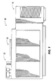
- Figure 1 is a schematic elevational view depicting an illustrative reproducing machine incorporating the apparatus of the present invention therein;
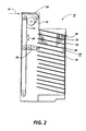
- Figure 2 is an elevational view depicting the details of the collating apparatus of the Figure 1 reproducing machine;
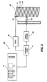
- Figure 3 is a block diagram illustrating the system used to control the Figure 2 collating apparatus.
- FIG. 1 schematically depicts the reproducing machine including the collating/sorting apparatus of the present invention. It will become evident from the following discussion that the apparatus of the present invention is equally well suited for use in a wide variety of printing systems or other types of devices wherein it is desired to sort or collate sheets.
- the features of the present invention are not specifically limited in their application to the particular embodiment depicted herein.
- the electrophotographic printing machine is capable of producing a stream of copy sheets having information copied either on one side only, simplex sheets, or on both sides, duplex sheets.
- a recirculating document feeder 12 is shown positioned above a platen at the imaging station of printing machine 10.
- Document feeder 12 is adapted to feed original documents, in seriatim, to the platen for copying.
- document feeder 12 operates in a collating mode, original documents are fed, in seriatim, from a stack in a tray at the top of the feeder to the platen for copying one at a time for each circulation and then returned to the stack.
- the original documents are placed in the feeder in a predetermined, page sequential order.
- the first page is on top of the stack and the last page is at the bottom of the stack.
- the last original document is sent to the platen first and then returned to the top of the stack.
- the machine operator can control operation of the electrophotographic printing machine and its related apparatus through an operator control panel designated generally by the reference numeral 14. To this end, the machine operator can determine whether a set of copies will be stored in a lockable or unlockable bin in the collating/sorting apparatus, designated generally by the reference numeral 16.
- the electrophotographic printing machine includes a belt having a photoconductive surface deposited on a a conductive substrate.
- the belt advances successive portions of the photoconductive surface to various processing stations disposed about the path of movement thereof. Initially, a portion of the belt passes through a charging station.
- a corona generating device charges the photoconductive surface of the belt to a relatively high, substantially uniform potential Thereafter, the charged portion of the photoconductive surface is advanced through the imaging station.
- an original document is advanced to a platen by recirculating document handling system 12. Lamps flash light rays onto the original document. The light rays reflected from the original document are transmitted through a lens forming a light image thereof.
- the lens focuses the light image onto the charged portion of the photoconductive surface to selectively dissipate the charge thereon.
- This records an electrostatic latent image on the photoconductive surface which corresponds to the informational areas contained within the original document disposed upon the platen.
- the belt advances the electrostatic latent image recorded on the photoconductive surface to a development station.
- a magnetic brush development system transports a developer mixture of carrier granules and toner particles into contact with the electrostatic latent image recorded on the photoconductive surface.
- the toner particles are attracted from the carrier granules to the electrostatic latent image forming a toner powder image on the photoconductive surface of the belt.
- the belt advances the toner powder image to a transfer station.
- a copy sheet is moved into contact with the toner powder image.
- a corona generating device sprays ions onto the backside of the copy sheet. This attracts the toner powder image from the photoconductive surface to the copy sheet.
- the copy sheet moves to the fusing station.
- the fusing station includes a fuser assembly which permanently affixes the transferred toner powder image to the copy sheet.
- the fuser assembly includes a heated fuser roll and back-up roll. The copy sheet passes between the fuser roll and the back-up roll with the toner powder image contacting the fuser roll. In this manner, the toner powder image is permanently affixed to the copy sheet.
- a conveyor belt guides the advancing sheet to collating/sorting apparatus 16.
- the advanced sheet is guided to the selected bin in collating/sorting apparatus.16.
- the bin selected may be a lockable bin or an unlockable bin.
- the destination of the copy sheet is determined by a code which the operator punches in on a numeric display on control panel 14.
- the numeric display sends a signal to suitable control logic,which, in turn, controls collating/sorting apparatus 16 such that the advancing copy sheet is guided to the appropriate bin. If a lockable bin is selected, the operator punches in the desired combination required to unlock the selected bin. Under these circumstances, the bin is locked and may only be opened with the selected combination.
- the printing machine control logic insures that the access doors to the interior of the printing machine are locked to prevent unauthorized access thereto during machine operation or in the event of a sheet jam.
- the foregoing describes generally the operation of the reproducing machine having a collating/sorting apparatus associated therewith. It is believed that the foregoing description is sufficient for purposes of the present application to illustrate the general operation of the system. The detailed structure of collating/sorting apparatus 16 and the associate control system will be described hereinafter, in greater detail, with reference to Figures 2 and 3.
- collating/sorting apparatus 16 is arranged adjacent the output of printing machine 10. As the copy sheet exits from the fuser, it is carried by a conveyor belt to the exit of printing 10. The sheet continues to move in the direction of arrow 18 on a conveyor belt 20.
- a deflection gate or chute 22 is arranged to deflect the sheet from the horizontal conveyor belt 20 onto a vertical conveyor belt 24. Conveyor belt 24 moves the sheet in a vertical direction downwardly until it engages a moving gate 26 which deflects the sheet into a bin 28.
- Collating/sorting apparatus 16 is composed of a plurality of sorting bins, indicated generally by the reference numeral 28, arranged in a parallel fashion, one above the other, to provide a vertical row of bins.
- Each bin is defined by a sheet receiving tray 30.
- bins 32, 34 and 36 are lockable whereas the remaining bins are unlockable.
- Lockable bins 32, 34, 36 included a hinged door 38.
- Door 38 is adapted to pivot downwardly so as to open lockable bins 32, 34 and 36 and enable the operator to have access to the interior thereof.
- Doors 38 are hinged on the lowermost portion thereof so that, as they pivot downwardly, they provide an additional surface for sliding copy sheets outwardly from the interior of the lockable bins 32, 34 and 36.
- Doors 38 are spring biased to pivot in an upwardly direction to return to the closed, locked position when not held open.
- An interlock switch is associated with doors 38 to detect when the door is in the open position. At this time, the printing machine may be disabled. Thus, the printing machine will not be capable of reproducing copies until the interlock switch indicates that all of the doors of the lockable bins are in the locked position.
- an electromagnet may be employed which is energized to lock the bins and de-energized to unlock the bins.
- a solenoid may be used in which the plunger thereof will engage an aperture in door 38 to positively secure the door in the locked position.
- the solenoid is de-energized, the plunger is retracted from the aperture in door 38 and door 38 may be pivoted to its opened position.
- the combination required to lock the bin may be punched in by the key operator on the numeric display panel of the reproducing machine.
- the remaining bins 28 are not lockable and, accordingly, do not require a hinged or pivotably mounted door and the associate lock.
- Gate 26 is mounted on a drive system for movement in a vertical direction.
- a suitable drive system may be a rack and pinion arrangement. As the pinion is rotated, the rack moves gate 26 vertically.
- the operator selects the desired bin by keypunching in the bin number on the numeric display of the control panel 14.
- This actuates an indexing motor of the drive system to rotate the pinion such that the rack advances the gate to the selected bin.
- gate 26 moves vertically in the directions of the arrow 40.
- the key operator may select either a lockable bin or an unlockable bin for receiving the copy sheets.
- control panel 14 includes a numeric display 42.
- the operator initially determines the bin to which the copy sheets are to be directed.
- the selected bin number is punched in on the numeric display 42.
- An output signal is transmitted from control panel 14 to control logic 44.
- Control logic 44 includes a closed loop servo system for regulating indexing motor 48.
- Indexing motor 48 rotates the pinion which moves the rack that advances gate 26 vertically.
- Indexing motor 48 is energized until the error signal from the servo system of control logic 44 is nulled. When the error signal from the servo system is nulled, motor 48 is de-energized.
- gate 26 no longer moves in a vertical direction and is positioned at the selected bin.
- the operator selects a lockable bin, i.e. bins 32, 34 or 36
- the operator key punches in on numeric display 42 the desired combination required to unlock the selected bin.
- Lock 46 which is associated with lockable bin is controlled by control logic 44.
- Control logic 44 transmits a signal de-energizing the electromagnetic or de-energizing the solenoid when the appropriate signal corresponding to the correct combination of numbers is received from numeric display 42.
- the copy sheet is guided to the selected lockable tray which, in the default condition, is locked.
- control logic 44 transmits a signal to lock 46 de-energizing the electromagnet or de-energizing the solenoid.
- lock 46 de-energizing the electromagnet or de-energizing the solenoid.
- the bin is unlocked, i.e. door 38 may be pivoted downwardly to provide access to the interior of the bin.
- lockable bins may have permanent combination codes assigned thereto.
- each lockable bin would have a permanent non-operator settable combination associated therewith. The operator would then only need to key punch in the pre-assigned combination to unlock the designated bin having the set of copy sheets therein. There would be no need to set the combination required to unlock the bin door.
- the laser printer is substantially the same as the reproducing machine with the exception that the optical system is no longer a light lens system, but rather a laser which is modulated in accordance with electrical signals received from the computer to record the desired electrostatic latent image on the photoconductive surface.
- This latent image is developed and transferred to the copy sheet. Thereafter, the latent image is permanently affixed thereto.
- the copy sheet is advanced to the selected bin.
- the selected bin is determined by the computer operator at the computer console.
- the computer operator may print out the desired information on the computer screen at a remote location, i.e. the laser printer.
- the resultant copy sheet is advanced to a selected bin.
- the computer operator selects whether the bin is to be a lockable bin or an unlockable bin.
- the selected bin is lockable, it may only be opened by an operator having the selected combination. Thus, only an individual having a need to know has access to the lockable bin holding the copy sheets with the confidential information thereon.
- the lockable bin may be employed by a plurality of operators with each operator selecting their own combination to unlock the bin. Under these circumstances, each operator will have their own combination which is not known by any other operator and provides access to the lockable bins by only that operator.
- a secure bin is provided for receiving confidential information.
- the collating/sorting apparatus of the present invention includes lockable and unlockable bins for receiving copy sheets from a reproducing machine.
- the key operator may select the destination of the copy sheets and define the required combination code to unlock a lockable bin. This ensures that confidential information being reproduced is accessible only to those who have a need to know.
Landscapes
- Physics & Mathematics (AREA)
- General Physics & Mathematics (AREA)
- Engineering & Computer Science (AREA)
- Mechanical Engineering (AREA)
- Collation Of Sheets And Webs (AREA)
- Paper Feeding For Electrophotography (AREA)
- Pile Receivers (AREA)
Claims (10)
- Blattverarbeitungsvorrichtung, enthaltend mehrere Fächer (28) zum Aufnehmen von Blättern darin,
gekennzeichnet durch
Einrichtungen (42, 44, 48, 26) zum Auswählen eines der Fächer zur Aufnahme von Blättern darin; und
Einrichtungen (46, 24) zum Verriegeln des zur Aufnahme der Blätter ausgewählten Fachs, um einen Zugang zu den Blättern, die sich in dem ausgewählten Fach befinden, durch Unberechtigte zu verhindern. - Vorrichtung nach Anspruch 1, enthaltend eine Einrichtung zum Entriegeln des verriegelten Fachs, um die Blätter daraus zu entnehmen.
- Vorrichtung nach Anspruch 1 oder 2, bei der wenigstens eines der anderen Fächer nicht verriegelbar ist.
- Vorrichtung nach Anspruch 3, bei der die Wähleinrichtung durch eine Bedienperson einstellbar ist, um entweder das verriegelbare Fach oder das entriegelbare Fach zur Aufnahme von Blättern darin auszuwählen.
- Vorrichtung nach Anspruch 4, enthaltend eine Einrichtung zum Einstellen eines Kombinationscodes zum Verriegeln des ausgewählten Fachs.
- Vorrichtung nach Anspruch 5, bei der die Einstelleinrichtung eine von einer Bedienperson betätigbare numerische Anzeige in Verbindung mit der Verriegelungseinrichtung aufweist, um es der Bedienperson zu ermöglichen, die zum Entriegeln des Fachs erforderliche Kombination zu programmieren.
- Vorrichtung nach Anspruch 6, bei der die Wähleinrichtung die numerische Anzeige zur Auswahl des das Blatt aufnehmenden Fachs enthält.
- Kopiergerät zum Herstellen von Kopien auf Papierblättern von Vorlagen, enthaltend eine Blattverarbeitungsvorrichtung gemäß einem der Ansprüche 1 bis 7.
- Kopiergerät nach Anspruch 8, bei dem die Wähleinrichtung an dem Gerät angeordnet ist.
- Kopiergerät nach Anspruch 8, bei dem die Wähleinrichtung abgesetzt von dem Gerät angeordnet ist.
Applications Claiming Priority (2)
| Application Number | Priority Date | Filing Date | Title |
|---|---|---|---|
| US85064986A | 1986-04-11 | 1986-04-11 | |
| US850649 | 1986-04-11 |
Publications (3)
| Publication Number | Publication Date |
|---|---|
| EP0241273A2 EP0241273A2 (de) | 1987-10-14 |
| EP0241273A3 EP0241273A3 (en) | 1988-01-20 |
| EP0241273B1 true EP0241273B1 (de) | 1991-07-03 |
Family
ID=25308753
Family Applications (1)
| Application Number | Title | Priority Date | Filing Date |
|---|---|---|---|
| EP87303038A Expired - Lifetime EP0241273B1 (de) | 1986-04-11 | 1987-04-08 | Begrenzter Zugang zu Kopiergerätefächer |
Country Status (3)
| Country | Link |
|---|---|
| EP (1) | EP0241273B1 (de) |
| JP (1) | JPS62259963A (de) |
| DE (1) | DE3771105D1 (de) |
Cited By (1)
| Publication number | Priority date | Publication date | Assignee | Title |
|---|---|---|---|---|
| US7180638B1 (en) | 2000-02-16 | 2007-02-20 | Ricoh Co., Ltd. | Network fax machine using a web page as a user interface |
Families Citing this family (20)
| Publication number | Priority date | Publication date | Assignee | Title |
|---|---|---|---|---|
| DK165237C (da) * | 1989-10-24 | 1993-03-08 | Iph Systems As | Arksorteringsindretning til en elektronisk styret arkskriver |
| EP0547788B1 (de) | 1991-12-16 | 1996-10-16 | Xerox Corporation | Wegnehmbares Haltesystem für Sets von Kopierbogen |
| EP0550033B1 (de) * | 1991-12-24 | 1997-04-02 | Seiko Epson Corporation | Papierschalenwahlvorrichtung in einem Drucker |
| US5328170A (en) * | 1992-03-10 | 1994-07-12 | Gradco (Japan) Ltd. | Locked drawer sorter |
| US5513013A (en) * | 1992-08-24 | 1996-04-30 | Xerox Corporation | Facsimile output job sorting unit and system |
| US5295181A (en) * | 1992-08-24 | 1994-03-15 | Xerox Corporation | Automatic facsimile output recipient telephoning system |
| US5270773A (en) * | 1992-11-27 | 1993-12-14 | Xerox Corporation | Image producing device with security to prevent disclosure of sensitive documents |
| DE69401377T2 (de) * | 1993-04-27 | 1997-07-10 | Xerox Corp | Briefverteilungssystem zum Zuführen von Bogen von einer Ausgabestelle zu ausgewählten Briefbehältern |
| US5358238A (en) * | 1993-04-27 | 1994-10-25 | Xerox Corporation | Shared user printer output dynamic "mailbox" system |
| US5342034A (en) * | 1993-04-27 | 1994-08-30 | Xerox Corporation | Mailbox/compiler architecture |
| US5328169A (en) * | 1993-05-05 | 1994-07-12 | Xerox Corporation | Mailbox or sorter bin use sensing system |
| US5390910A (en) * | 1993-05-24 | 1995-02-21 | Xerox Corporation | Modular multifunctional mailbox unit with interchangeable sub-modules |
| US5308058A (en) * | 1993-05-25 | 1994-05-03 | Xerox Corporation | Mailbox security door with automatic set lifter |
| US5602973A (en) * | 1993-09-30 | 1997-02-11 | Ricoh Company, Ltd. | Printer providing security for printout |
| US5505442A (en) * | 1994-05-26 | 1996-04-09 | Chang; Joseph | Electronically distributing and confidential paper receiver |
| US5551686A (en) * | 1995-02-23 | 1996-09-03 | Xerox Corporation | Printing and mailbox system for shared users with bins almost full sensing |
| US5697761A (en) | 1996-01-11 | 1997-12-16 | Xerox Corporation | Mailbox bin job set extractor |
| DE19707162A1 (de) * | 1997-02-22 | 1998-08-27 | Eastman Kodak Co | Verfahren und Vorrichtung zum Ablegen und/oder Weitertransport von Kopier- oder Druckaufträgen |
| US6917765B2 (en) | 2002-03-21 | 2005-07-12 | Hewlett-Packard Development Company, L.P. | Imaging device access control apparatus |
| US7570398B2 (en) | 2006-10-10 | 2009-08-04 | Ricoh Company, Ltd. | Secure scanning device |
Family Cites Families (3)
| Publication number | Priority date | Publication date | Assignee | Title |
|---|---|---|---|---|
| DE3021504C2 (de) * | 1980-06-07 | 1983-05-05 | Ibm Deutschland Gmbh, 7000 Stuttgart | Zugangsgesichertes Kopiergerät |
| US4437660A (en) * | 1981-11-16 | 1984-03-20 | Datapoint Corporation | Word processor--controlled printer output scanner mechanism |
| US4470356A (en) * | 1982-02-09 | 1984-09-11 | Datapoint Corporation | Word processor-controlled printer output bin lock box |
-
1987
- 1987-04-03 JP JP62081367A patent/JPS62259963A/ja active Pending
- 1987-04-08 EP EP87303038A patent/EP0241273B1/de not_active Expired - Lifetime
- 1987-04-08 DE DE8787303038T patent/DE3771105D1/de not_active Expired - Fee Related
Cited By (1)
| Publication number | Priority date | Publication date | Assignee | Title |
|---|---|---|---|---|
| US7180638B1 (en) | 2000-02-16 | 2007-02-20 | Ricoh Co., Ltd. | Network fax machine using a web page as a user interface |
Also Published As
| Publication number | Publication date |
|---|---|
| EP0241273A3 (en) | 1988-01-20 |
| DE3771105D1 (de) | 1991-08-08 |
| JPS62259963A (ja) | 1987-11-12 |
| EP0241273A2 (de) | 1987-10-14 |
Similar Documents
| Publication | Publication Date | Title |
|---|---|---|
| EP0241273B1 (de) | Begrenzter Zugang zu Kopiergerätefächer | |
| US4739377A (en) | Confidential document reproduction method and apparatus | |
| US3709595A (en) | Printer system | |
| JPH01500698A (ja) | 挿入モードで動作可能な複写機 | |
| JPS61174063A (ja) | シ−ト分配装置 | |
| US4136862A (en) | Paper orientation for duplexing and collating | |
| EP0263398B1 (de) | Automatische Dokumentenzuführvorrichtung | |
| JPH0691596B2 (ja) | ジョブ出力分離システム | |
| US4714241A (en) | Recirculating document feeder | |
| US3845949A (en) | Sorter control to prevent over-stacking in the sorter trays | |
| EP0473434B1 (de) | Gerät mit Auftragsintegrität und -sicherheit | |
| JPH0615383B2 (ja) | 画像記録装置 | |
| EP0029109B1 (de) | Verfahren zur Herstellung mehrseitiger Dokumente in einem Kopier- und Drucksystem | |
| CA2334544C (en) | Method and apparatus for charging for printing operations on an electrophotographic printing machine | |
| EP0457552B1 (de) | Vervielfältigungsgerät | |
| US4956666A (en) | Secure copier and method of reproduction | |
| EP0532343B1 (de) | Blattzuführapparat mit seitlicher Ausrichtung | |
| EP0418029B1 (de) | Vervielfältigungssystem | |
| CN100501580C (zh) | 具有运行时卸载的安全保护装置的纸张复印文本生成设备 | |
| US5493367A (en) | Reproduction apparatus and method for correctly orienting principal copies and supplemental copies | |
| US5204727A (en) | Image forming apparatus | |
| US5599010A (en) | Automatic loading/unloading of a document feeder for a reproduction apparatus | |
| JP2556303B2 (ja) | 記録紙分類装置 | |
| US4078791A (en) | Gate mechanism for a copier machine | |
| CA1054968A (en) | Sorter control system |
Legal Events
| Date | Code | Title | Description |
|---|---|---|---|
| PUAI | Public reference made under article 153(3) epc to a published international application that has entered the european phase |
Free format text: ORIGINAL CODE: 0009012 |
|
| AK | Designated contracting states |
Kind code of ref document: A2 Designated state(s): DE FR GB IT |
|
| PUAL | Search report despatched |
Free format text: ORIGINAL CODE: 0009013 |
|
| AK | Designated contracting states |
Kind code of ref document: A3 Designated state(s): DE FR GB IT |
|
| 17P | Request for examination filed |
Effective date: 19880630 |
|
| 17Q | First examination report despatched |
Effective date: 19901011 |
|
| GRAA | (expected) grant |
Free format text: ORIGINAL CODE: 0009210 |
|
| AK | Designated contracting states |
Kind code of ref document: B1 Designated state(s): DE FR GB IT |
|
| ET | Fr: translation filed | ||
| REF | Corresponds to: |
Ref document number: 3771105 Country of ref document: DE Date of ref document: 19910808 |
|
| ITF | It: translation for a ep patent filed | ||
| PLBE | No opposition filed within time limit |
Free format text: ORIGINAL CODE: 0009261 |
|
| STAA | Information on the status of an ep patent application or granted ep patent |
Free format text: STATUS: NO OPPOSITION FILED WITHIN TIME LIMIT |
|
| 26N | No opposition filed | ||
| PGFP | Annual fee paid to national office [announced via postgrant information from national office to epo] |
Ref country code: DE Payment date: 20010402 Year of fee payment: 15 |
|
| PGFP | Annual fee paid to national office [announced via postgrant information from national office to epo] |
Ref country code: GB Payment date: 20010404 Year of fee payment: 15 |
|
| PGFP | Annual fee paid to national office [announced via postgrant information from national office to epo] |
Ref country code: FR Payment date: 20010409 Year of fee payment: 15 |
|
| REG | Reference to a national code |
Ref country code: GB Ref legal event code: IF02 |
|
| PG25 | Lapsed in a contracting state [announced via postgrant information from national office to epo] |
Ref country code: GB Free format text: LAPSE BECAUSE OF NON-PAYMENT OF DUE FEES Effective date: 20020408 |
|
| PG25 | Lapsed in a contracting state [announced via postgrant information from national office to epo] |
Ref country code: DE Free format text: LAPSE BECAUSE OF NON-PAYMENT OF DUE FEES Effective date: 20021101 |
|
| GBPC | Gb: european patent ceased through non-payment of renewal fee |
Effective date: 20020408 |
|
| PG25 | Lapsed in a contracting state [announced via postgrant information from national office to epo] |
Ref country code: FR Free format text: LAPSE BECAUSE OF NON-PAYMENT OF DUE FEES Effective date: 20021231 |
|
| REG | Reference to a national code |
Ref country code: FR Ref legal event code: ST |
|
| PG25 | Lapsed in a contracting state [announced via postgrant information from national office to epo] |
Ref country code: IT Free format text: LAPSE BECAUSE OF NON-PAYMENT OF DUE FEES;WARNING: LAPSES OF ITALIAN PATENTS WITH EFFECTIVE DATE BEFORE 2007 MAY HAVE OCCURRED AT ANY TIME BEFORE 2007. THE CORRECT EFFECTIVE DATE MAY BE DIFFERENT FROM THE ONE RECORDED. Effective date: 20050408 |