EP0241164A2 - Füllhöhendetektor in einem Wiege- und Verpackungssystem - Google Patents
Füllhöhendetektor in einem Wiege- und Verpackungssystem Download PDFInfo
- Publication number
- EP0241164A2 EP0241164A2 EP87302311A EP87302311A EP0241164A2 EP 0241164 A2 EP0241164 A2 EP 0241164A2 EP 87302311 A EP87302311 A EP 87302311A EP 87302311 A EP87302311 A EP 87302311A EP 0241164 A2 EP0241164 A2 EP 0241164A2
- Authority
- EP
- European Patent Office
- Prior art keywords
- package
- probe
- product
- weighing
- level
- Prior art date
- Legal status (The legal status is an assumption and is not a legal conclusion. Google has not performed a legal analysis and makes no representation as to the accuracy of the status listed.)
- Withdrawn
Links
Images


Classifications
-
- G—PHYSICS
- G01—MEASURING; TESTING
- G01G—WEIGHING
- G01G15/00—Arrangements for check-weighing of materials dispensed into removable containers
- G01G15/02—Arrangements for check-weighing of materials dispensed into removable containers with provision for adding or removing a make-up quantity of material to obtain the desired net weight
-
- G—PHYSICS
- G01—MEASURING; TESTING
- G01G—WEIGHING
- G01G15/00—Arrangements for check-weighing of materials dispensed into removable containers
- G01G15/001—Volumetric pre-dispensing to an estimated weight; Gravimetric make-up device for target device
Definitions
- the invention relates generally to packaging systems and deals more particularly with an apparatus for detecting whether a package is filled to a proper level and also deals with a weighing and packaging system which includes the aforesaid apparatus and regulates a package target weight in a stable manner to control the product level in the package.
- the composite density of certain types of products may vary significantly, for example, that of cereals or other products which contain a large number of pieces per package which pieces vary in size and shape.
- the random arrangement of the pieces within a package and degree of settling also affect the composite density and resultant volume of the product.
- the package size is often selected such that for a given weight of the product, the average product height is somewhat below the maximum fill height of the package. Settling may occur after a package is initially filled so that it is important that the package be initially filled as high as possible, but nevertheless with the restraint that few or none of the batches of product overflow the package.
- a general object of the present invention is to provide an apparatus for detecting whether a package is filled to a proper height.
- Another general object of the invention is to provide an apparatus of the foregoing type which may be included within a weighing and packaging system without decreasing the packaging rate.
- a more specific object of the invention is to provide a system of the foregoing type in which the height of the product in the package when detected approximates the height of the product when the package is obtained by a consumer.
- Another specific object of the present invention is to provide a weighing and packaging system including the foregoing apparatus as one component, which system includes means for adjusting a package weight to regulate fill height.
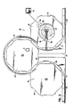
- Figs. l and 2 illustrate a weighing and packaging system generally designated l0 in which the invention is embodied.
- the system l0 comprises a package feeding assembly l2, a weighing and packaging machine l4, a computer controller l6, a fill height detector l8, and a vibrator 3 which is coupled to the feeding assembly l2.
- the feeding assembly l2 comprises circular, rotatable tables l9, 20 and 2l, peripheral guide bars 24, 25, 26, guide plates 27, and a flexible conveyor belt 28 which circulates first around the table l9 then around the table 20 and then around the table 2l.
- Each of the tables l9, 20 and 2l has teeth equally spaced about its perimeter which teeth form pockets 22 for receiving packages ll,ll and moving them from table to table.
- the weighing and packaging machine l4 may comprise one of various types of weighers, for example a combination weigher 5 as disclosed in U.S. Patent 4,550,792 to Mosher et al, issued November 5, l985, assigned to the assignee of the present invention and hereby adopted by reference as part of the present disclosure or a noncombination weigher.
- the combination weigher 5 comprises weighing scales l,l, time fill or accumulator buckets 6,6 which rapidly supply the weighing scales l,l with product, a vibrating product feed assembly 4 for supplying the accumulator buckets at a gradual rate with a fraction of a package target weight of the product, and an input conveyor 8 for delivering product to the feed assembly 4.
- the weighing scales l,l discharge into a common discharge chute or funnel 7 which common chute 7 fills rotary discharge chutes 23,23, one at a time, with the target weight of the product.
- the packages ll,ll revolve in table 20 beneath the weighing machine 5 in synchronization with the rotary discharge chutes 23,23 to receive the product.
- a vibrator 3 is coupled to the table 20 and is continuously active. While the packages ll,ll are located beneath the weighing machine l4 and receive product via the chutes 23,23, the vibrations prevent the product from clogging the chutes and the tops of the packages. Also, while the packages travel around the table 20 enroute to the table 2l and the fill height detector l8, the vibrations help the product to settle in the packages and thereby obtain a level similar to that which will exist in the packages when opened by a consumer.
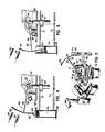
- the fill height detector l8 comprises a probe assembly 36, a cam 37, and two sensors 40,42 which sense the position of the probe assembly 36.
- the table 2l may also be considered as part of the fill height detector l8.
- the probe assembly 36 includes a probe 50, a first vane or arm 52 which supports the probe at one end, a flag 53 fixedly attached to the other end of the arm 52 and a second vane or arm 54 which supports the arm 52.
- the arm 54 is pivotly mounted to a shaft 47 by a horizontal pivot pin 43, which shaft is received within an aperture 44 in the top of the table 2l and fixed to the table by a clamp 46 so that the probe assembly revolves in synchronization with the table 2l.
- the computer controller l6 also controls a motor 65 which drives the table 2l (Fig. 2) via a gear assembly 66 and the probe assembly 36 in a counterclockwise direction in the illustrated embodiment which controller l6 also tracks the rotation of the motor and therefore, the angular position of the table 2l.
- the cam 37 is fixedly mounted at an adjustable height by a support bracket 48 to a stationary post 49.
- a cam follower in the form of a wheel 59 within the probe assembly 36 is rotably mounted to the arm 54 of the probe assembly via a bracket 55 and moves along the top edge of the cam as the table rotates.
- the cam is formed by cylindrical side wall portions 6l,62,63 and 64 and a washer-shaped base portion 60 and has a gap 67 aligned with the sensors 40 and 42.
- the portion 63 extends approximately l50 degrees and has an approximately level upper edge upon which the wheel 59 travels. While the wheel 59 travels on the portion 63, (Fig. 4) the probe assembly is maintained at a substantially fixed elevation. Next, the wheel 59 encounters the portion 64 of the cam 37 which portion is taller than the portion 63 so that the probe assembly moves upwardly. Simultaneously, one of the packages ll a (shown at a subsequent position in Fig.
- the weight of the probe 50, the arms 52 and 54 and the flag 53 is offset to a large degree by a counterbalance 57 so that the probe 50 contacts the product with a light force and does not penetrate into or damage the product.
- a bottom face 69 of the probe is broad enough to distribute the contact force on the product so that the probe does not penetrate into the product and rests at a level which closely approximates the top level of the product in the package.
- the sensors 40 and 42 are magnetic and the arm 52 and the flag 53 are metal; however, if desired, photoelectric sensors may be substituted.
- the sensor 40 comprises a normally closed switch which opens when either the arm 52 or the flag 53 are positioned in front of the sensor 40.
- the sensor 42 comprises a normally open switch which closes when either the arm 52 or the flag 53 are posi tioned in front of the sensor 42. Consequently, when the probe assembly is positioned midway in the gap 67, one of two conditions occurs. As shown in Fig.
- the flag 53 will be positioned so that its top edge is beneath the level of the magnetic sensor 40 and above the level of the magnetic sensor 42 so that the magnetic sensor 40 exhibits its deactivated, closed position while the magnetic sensor 42 attains its activated, closed position.
- the magnetic sensors 40 and 42 are connected in series so that in the aforesaid situation where the fill height is low, the input of a latch 72 is grounded, and set at a "one" state.
- the package ll a is filled to a sufficiently high level so that the probe rests on top of the product before the wheel 59 engages the base portion 60 and before the top edge of the flag 53 dips below the level of the magnetic sensor 40, then the magnetic sensor 40 is activated and opened shortly before the magnetic sensor 42 is activated and closed. Consequently, a voltage will be applied through a pull-up register 74 to the input of the latch l02 and sets the latch in a "zero" state.
- the state of the latch l02 is sensed at its ouput by the computer controller l6 so that the computer learns whether the package ll a has been filled to a sufficiently high level or not. If the probe assembly 36 breaks and does not set the latch at all in accordance with the actual fill height, the sensor 42 remains open to indicate the fill height is not low. Under these circumstances, a low fill height signal is prevented from being repeatedly sent to the computer controller l6. Thus the fill height detector is fail safe.
- the wheel 59 soon encounters the portion 62 of the cam 37 which portion is inclined upwardly so that the wheel 59 and the probe assembly 36 move upwardly and the probe 50 rises out of the top of the package ll a .
- the package moves downstream along the conveyor to a subsequent site where the package may be sealed or be subject to another function.
- the probe assembly 36 also continues to revolve around the cam 37 and after revolving to the gap 67 again, samples the height of another one of packages ll,ll to continue the fill height detection process. In the embodiment illustrated in Fig. 2, the fill height in every eighth package is checked.
- the flow chart of Fig. 7 illustrates a method by which the computer controller l6 utilizes the fill height detection information to adjust the desired weight of product in each package and thereby control fill height.
- the computer controller l6 waits until twenty dumps have occurred before sampling of the output latch l02 and adjusting the desired package weight upwardly or downwardly.
- the waiting loop is entered from branch 84 and waits at instruction 86 for a dump signal during each pass through the loop.
- the twenty dumps allow the weighing and packaging system to stabilize and produce relatively uniform charges and heights of product in each package at the initialized parameters.
- the computer controller l6 enables latch l02 at step 88 so that the conditions of sensors 40 and 42 can be monitored.
- An internal dump counter which may also be used in connection with branch 84, is set at step 90 to a count of l0 and is immediately decremented to count 9 at step 92.
- the latch l02 is then sampled at step 94 to determine whether the fill level in a package that has been probed by the fill height detector l8 is above or below the desired level.
- the latch l02 Since the latch l02 was enabled only a brief instant before, it is unlikely that a package will have been probed by the detector l8, and therefore, the latch is set at the unlatched or "zero" state indicating that the level is not low and no adjustment is required.
- the computer controller then follows the program loop from branch 96 through step l06 and branch l08 to decrement the counter with each dump cycle until finally a package is probed by the detector l8.
- the computer enters the loop for incrementally increasing the fill height.
- the program clears the latch at step 98, and increases a target bias weight by a predetermined amount at step l00.
- the target bias value is that incremental weight that is added to the target weight and causes the combination weighing system to search for and dump charges of product which are larger than the target weight by the amount of the bias weight.
- step l00 the program advances and resets the dump counter to a 9-count at step l04. Thereafter, the program proceeds to instruction l06 and waits for a dump signal.
- the counter is then interrogated at branch l08 to determine if the counter has been decremented to a zero count, and obviously on the first pass through the branch l08 from step l04 the count will be 9 so the program proceeds to decrement the counter in the main loop at step 92.
- the latch l02 is sampled, but since the fill height detector does not probe the next seven packages, the latch remains in the unlatched or "zero" state indicating the level is not low.
- step l06 and branch l08 to decrement the counter is thus followed for nine dumps, or until the fill height detector l8 senses a low fill height in the eighth package and sets the latch l02 in the "one" state to increase the target bias weight as described above.
- the program advances from branch l08 to step ll0 where the target weight bias is automatically decreased by an incremental amount.
- the decrease in bias weight prevents the fill height and weight of delivered product from growing uncontrollably large for any reason such as a decrease in product density or a malfunction of the detector l8.
- step ll0 does not decrease the bias weight below zero and thus reduce the package weight below the target weight
- the program advances from step ll0 to branch ll2 and tests the new bias weight value. If the bias weight is greater than zero, the weighing machine is advised, and the program advances directly to steps 90 and 92. These steps put the counter at 9-count to allow at least eight more packages to pass before the fill height detector l8 again sets the latch l02. If the decrease at step ll0 caused the bias weight to drop below zero, the program advances to step ll4 and sets the bias weight to a zero value and then advances to step 90. Thus, in no event, will the target bias weight be reduced below zero, and the delivered package weight will not drop below the target weight.
- the program illustrated in Fig. 7 is designed to control the fill level about a desired fill height established by the position of the sensors 40 and 42 and includes the step ll0 for decreasing the target bias as well as the step l00 for increasing the target bias weight in what is effectively close loop control.
- the program can also favor increases of the bias weight, so that the bias is increased more rapidly than it is decreased. This feature encourages the fill heights to be rapidly returned to the desired level if the detected level is low and is implemented, for example, simply by doubling the count set at step 90.
- a weighing and packaging system including a fill-height detector has been disclosed.
- numerous modifications and substitutions may be made without deviating from the scope of the invention.
- a sensor or sensors located adjacent to the pin 43 may be utilized to detect the angular displacement of the arm 54 instead of the sensors 40 and 42.
- the portion 63 of the cam 37 may be inclined gradually upwardly from the top of the inclined portion 62 to the top of the portion 64.
- another vibrator may be coupled to the table 2l to facilitate settling of the product.
- the invention has been disclosed by way of illustration and not limitation.
Landscapes
- Physics & Mathematics (AREA)
- General Physics & Mathematics (AREA)
- Basic Packing Technique (AREA)
- Weight Measurement For Supplying Or Discharging Of Specified Amounts Of Material (AREA)
- Auxiliary Devices For And Details Of Packaging Control (AREA)
Applications Claiming Priority (2)
| Application Number | Priority Date | Filing Date | Title |
|---|---|---|---|
| US06/849,032 US4657094A (en) | 1986-04-07 | 1986-04-07 | Fill height detector in weighing and packaging system |
| US849032 | 1986-04-07 |
Publications (2)
| Publication Number | Publication Date |
|---|---|
| EP0241164A2 true EP0241164A2 (de) | 1987-10-14 |
| EP0241164A3 EP0241164A3 (de) | 1988-10-05 |
Family
ID=25304900
Family Applications (1)
| Application Number | Title | Priority Date | Filing Date |
|---|---|---|---|
| EP87302311A Withdrawn EP0241164A3 (de) | 1986-04-07 | 1987-03-18 | Füllhöhendetektor in einem Wiege- und Verpackungssystem |
Country Status (4)
| Country | Link |
|---|---|
| US (1) | US4657094A (de) |
| EP (1) | EP0241164A3 (de) |
| JP (1) | JPS62273413A (de) |
| CA (1) | CA1269743A (de) |
Cited By (1)
| Publication number | Priority date | Publication date | Assignee | Title |
|---|---|---|---|---|
| CN110803313A (zh) * | 2019-11-11 | 2020-02-18 | 青岛锐智智能装备科技有限公司 | 一种带棒状物自动理料功能的定量包装多头组合秤 |
Families Citing this family (6)
| Publication number | Priority date | Publication date | Assignee | Title |
|---|---|---|---|---|
| DE3938220A1 (de) * | 1989-11-17 | 1991-05-23 | Benz & Hilgers Gmbh | Verfahren und vorrichtung zum verpacken von pastoesen produkten, wie suppenpasten, margarine, butter oder dgl. in form von paeckchen, wuerfeln oder dgl. |
| ES2051115T3 (es) * | 1990-07-05 | 1994-06-01 | Hormec Technic Sa | Distribuidor de dosis de fluido, en particular para el encolado de piezas. |
| US5538140A (en) * | 1994-10-19 | 1996-07-23 | Bell & Howell Company | Buffered stacker with drop floor assembly |
| US5503388A (en) * | 1994-10-19 | 1996-04-02 | Bell & Howell Company | Buffered stacker |
| DE102008020256A1 (de) * | 2008-04-22 | 2009-10-29 | Haver & Boecker Ohg | Packanlage |
| CN105501530B (zh) * | 2014-09-11 | 2017-12-05 | 南京新侨鑫环保科技有限公司 | 秤重装置 |
Family Cites Families (11)
| Publication number | Priority date | Publication date | Assignee | Title |
|---|---|---|---|---|
| US3097459A (en) * | 1963-07-16 | rausch | ||
| GB445279A (en) * | 1934-10-02 | 1936-04-02 | British Cardboard Box Machine | Improvements in or relating to an apparatus for testing or determining the degree offilling of packages, cartons or the like |
| US2286130A (en) * | 1940-07-24 | 1942-06-09 | Pneumatic Soale Corp Ltd | Packaging machine |
| DE1057952B (de) * | 1955-03-14 | 1959-05-21 | Pneumatic Scale Corp | Regelbare Verdichtungseinrichtung bei automatischen Verpackungsmaschinen |
| US2746222A (en) * | 1955-04-21 | 1956-05-22 | Redington Co F B | Detector mechanism for a packaging machine |
| DE1174246B (de) * | 1961-07-04 | 1964-07-16 | Industrial Nucleonics Corp | Anordnung zum Regeln der Fuellhoehe an einer Abfuellmaschine |
| US3430814A (en) * | 1967-07-19 | 1969-03-04 | Cities Service Athabasca Inc | Solid interphase indicator controller |
| CH647596A5 (fr) * | 1982-04-01 | 1985-01-31 | Battelle Memorial Institute | Procede pour determiner le volume de liquide contenu dans un recipient ferme et dispositif pour la mise en oeuvre de ce procede. |
| JPS5946821A (ja) * | 1982-09-11 | 1984-03-16 | Ishida Scales Mfg Co Ltd | 組み合せ計量方法 |
| US4548286A (en) * | 1982-12-03 | 1985-10-22 | Kabushiki Kaisha Ishida Koki Seisakusho | Combinatorial weighing method and apparatus with volume and density sensing |
| DE3536173A1 (de) * | 1985-10-10 | 1987-04-16 | Bosch Gmbh Robert | Vorrichtung zum abmessen und abfuellen von mengen aus zerbrechlichem stueckigem gut |
-
1986
- 1986-04-07 US US06/849,032 patent/US4657094A/en not_active Expired - Fee Related
-
1987
- 1987-03-18 EP EP87302311A patent/EP0241164A3/de not_active Withdrawn
- 1987-03-27 CA CA000533139A patent/CA1269743A/en not_active Expired - Fee Related
- 1987-04-07 JP JP62085597A patent/JPS62273413A/ja active Pending
Cited By (1)
| Publication number | Priority date | Publication date | Assignee | Title |
|---|---|---|---|---|
| CN110803313A (zh) * | 2019-11-11 | 2020-02-18 | 青岛锐智智能装备科技有限公司 | 一种带棒状物自动理料功能的定量包装多头组合秤 |
Also Published As
| Publication number | Publication date |
|---|---|
| US4657094A (en) | 1987-04-14 |
| JPS62273413A (ja) | 1987-11-27 |
| EP0241164A3 (de) | 1988-10-05 |
| CA1269743A (en) | 1990-05-29 |
Similar Documents
| Publication | Publication Date | Title |
|---|---|---|
| EP0152923B1 (de) | Vorrichtung zur Portionierung von Produkten | |
| EP0348077B1 (de) | Vorrichtung zum automatischen Einfüllen und Verpacken von Produktmengen bestimmten Gewichtes in Behälter | |
| EP0103475A2 (de) | Verfahren und Vorrichtung zum Wiegen und Verpacken | |
| CA1264697A (en) | Apparatus and method for producing weighed batches of aligned elongated articles | |
| EP0112664B1 (de) | Automatischer Wägeapparat und Methode | |
| EP1698555B1 (de) | Verpackungsmaschine mit wägevorrichtung | |
| CN105197263B (zh) | 一种填充机及其填充工艺 | |
| US6000200A (en) | Bagging apparatus | |
| US4753306A (en) | Combination weighing method and apparatus using multi-bin scales | |
| GB1013130A (en) | Self correcting weighing machine and method | |
| EP1164365B1 (de) | KOMBINATIONSWAAGE UND ZäHLVORRICHTUNG | |
| EP0241164A2 (de) | Füllhöhendetektor in einem Wiege- und Verpackungssystem | |
| EP0097530B1 (de) | Kombinatorischer Wägeapparat | |
| US4515231A (en) | Combinatorial weighing apparatus with serial weighing operations | |
| EP0104062A2 (de) | Methoden zum automatischen Wiegen und Verpacken und Apparat hierfür | |
| US4828054A (en) | Combination weigher having a standby product charge | |
| US4681176A (en) | Product handling and weighing apparatus | |
| US4766964A (en) | Apparent density measuring device | |
| EP3832270B1 (de) | Abhilfe-beurteilungssystem | |
| EP0534889B1 (de) | Automatische Waage für Nahrungsmittel | |
| JPH0122886B2 (de) | ||
| CN212397334U (zh) | 条状物品检重秤 | |
| CN109094826A (zh) | 微量称重分装机及其称量分装方法 | |
| WO2000073748A1 (fr) | Mecanisme de distribution d'objets peses et dispositif de pesee | |
| JPH0765923B2 (ja) | 充填装置における充填量秤量装置 |
Legal Events
| Date | Code | Title | Description |
|---|---|---|---|
| PUAI | Public reference made under article 153(3) epc to a published international application that has entered the european phase |
Free format text: ORIGINAL CODE: 0009012 |
|
| AK | Designated contracting states |
Kind code of ref document: A2 Designated state(s): AT BE CH DE ES FR GB GR IT LI LU NL SE |
|
| PUAL | Search report despatched |
Free format text: ORIGINAL CODE: 0009013 |
|
| AK | Designated contracting states |
Kind code of ref document: A3 Designated state(s): AT BE CH DE ES FR GB GR IT LI LU NL SE |
|
| 17P | Request for examination filed |
Effective date: 19881006 |
|
| 17Q | First examination report despatched |
Effective date: 19900109 |
|
| STAA | Information on the status of an ep patent application or granted ep patent |
Free format text: STATUS: THE APPLICATION IS DEEMED TO BE WITHDRAWN |
|
| 18D | Application deemed to be withdrawn |
Effective date: 19900522 |
|
| RIN1 | Information on inventor provided before grant (corrected) |
Inventor name: MOSHER, OREN A. Inventor name: MOSHER, OREN G. |