EP0240956B1 - Apparatus for twisting yarns - Google Patents
Apparatus for twisting yarns Download PDFInfo
- Publication number
- EP0240956B1 EP0240956B1 EP87105009A EP87105009A EP0240956B1 EP 0240956 B1 EP0240956 B1 EP 0240956B1 EP 87105009 A EP87105009 A EP 87105009A EP 87105009 A EP87105009 A EP 87105009A EP 0240956 B1 EP0240956 B1 EP 0240956B1
- Authority
- EP
- European Patent Office
- Prior art keywords
- yarn
- spindle
- thread
- conveyor
- rotary body
- Prior art date
- Legal status (The legal status is an assumption and is not a legal conclusion. Google has not performed a legal analysis and makes no representation as to the accuracy of the status listed.)
- Expired - Lifetime
Links
- 230000005484 gravity Effects 0.000 claims description 2
- 241001589086 Bellapiscis medius Species 0.000 claims 22
- 230000007423 decrease Effects 0.000 claims 1
- 239000004753 textile Substances 0.000 claims 1
- 238000009944 hand knitting Methods 0.000 description 5
- 230000009471 action Effects 0.000 description 4
- 230000007246 mechanism Effects 0.000 description 4
- 230000008859 change Effects 0.000 description 3
- 239000003086 colorant Substances 0.000 description 3
- 230000008901 benefit Effects 0.000 description 2
- 230000000694 effects Effects 0.000 description 2
- 241001474791 Proboscis Species 0.000 description 1
- 239000011324 bead Substances 0.000 description 1
- 230000005540 biological transmission Effects 0.000 description 1
- 230000006835 compression Effects 0.000 description 1
- 238000007906 compression Methods 0.000 description 1
- 230000008878 coupling Effects 0.000 description 1
- 238000010168 coupling process Methods 0.000 description 1
- 238000005859 coupling reaction Methods 0.000 description 1
- 230000001419 dependent effect Effects 0.000 description 1
- 238000000151 deposition Methods 0.000 description 1
- 239000004744 fabric Substances 0.000 description 1
- 230000006870 function Effects 0.000 description 1
- 230000006872 improvement Effects 0.000 description 1
- 239000000463 material Substances 0.000 description 1
- 238000004804 winding Methods 0.000 description 1
Images


Classifications
-
- D—TEXTILES; PAPER
- D01—NATURAL OR MAN-MADE THREADS OR FIBRES; SPINNING
- D01H—SPINNING OR TWISTING
- D01H1/00—Spinning or twisting machines in which the product is wound-up continuously
- D01H1/10—Spinning or twisting machines in which the product is wound-up continuously for imparting multiple twist, e.g. two-for-one twisting
-
- D—TEXTILES; PAPER
- D01—NATURAL OR MAN-MADE THREADS OR FIBRES; SPINNING
- D01H—SPINNING OR TWISTING
- D01H13/00—Other common constructional features, details or accessories
- D01H13/04—Guides for slivers, rovings, or yarns; Smoothing dies
-
- D—TEXTILES; PAPER
- D01—NATURAL OR MAN-MADE THREADS OR FIBRES; SPINNING
- D01H—SPINNING OR TWISTING
- D01H7/00—Spinning or twisting arrangements
- D01H7/02—Spinning or twisting arrangements for imparting permanent twist
- D01H7/86—Multiple-twist arrangements, e.g. two-for-one twisting devices ; Threading of yarn; Devices in hollow spindles for imparting false twist
- D01H7/866—Means to facilitate the unwinding of yarn
-
- D—TEXTILES; PAPER
- D01—NATURAL OR MAN-MADE THREADS OR FIBRES; SPINNING
- D01H—SPINNING OR TWISTING
- D01H7/00—Spinning or twisting arrangements
- D01H7/02—Spinning or twisting arrangements for imparting permanent twist
- D01H7/86—Multiple-twist arrangements, e.g. two-for-one twisting devices ; Threading of yarn; Devices in hollow spindles for imparting false twist
- D01H7/868—Yarn guiding means, e.g. guiding tubes
Definitions
- the invention relates to a thread twisting device for twisting a multiplicity of threads, having a driven thread spindle and a thread conveyor connected downstream in the thread run and driven in a defined ratio adapted to the desired degree of twist.
- a thread twisting device for twisting a multiplicity of threads, having a driven thread spindle and a thread conveyor connected downstream in the thread run and driven in a defined ratio adapted to the desired degree of twist.
- the threads are placed on a bobbin as a supply spool, brought together and twisted together to form a thread.
- Thread twisting devices based on the double wire twisting principle are particularly suitable for the application described above, because the bobbin plate does not rotate and therefore relatively high spindle speeds can be achieved, even if the mass of the supply bobbins is not distributed rotationally symmetrically on the bobbin plate.
- Supply spools with different fillings can thus be used and some or more of the plug-on devices for supply spools can also remain vacant.
- the thread twisting device can be arranged with an oblique or horizontal axis, a weight preferably being used to hold the bobbin plate in a rotationally asymmetrical manner on the bobbin plate.
- the object of the invention is to provide a thread twisting device in which there is the possibility, on the one hand, of continuously changing the color of the thread by briefly exchanging the supply spools and, on the other hand, of making the twisted thread thus produced immediately available for further processing with a fluctuating demand.
- a thread twisting device to which a thread store with quantity sensing is assigned, and in which the drive of the twisting spindle and the thread conveyor is switched synchronously by the quantity sensing or with a small time offset.
- care is therefore taken to ensure that a fixed, preferably selectable ratio between the thread conveying speed and the twisting spindle speed is ensured with a single drive and that the thread is provided with a defined twisting (twists per meter).
- twisting spindle is also an integral part of the thread conveyor.
- the thread store can be connected downstream of the thread conveyor or be part of the thread conveyor.
- the thread conveyor is formed by the spindle end and a pressure roller pressed resiliently against the surface of the spindle end.
- the thread twisting device is designed as a double-wire twisting spindle
- the end of the spindle which faces away from the bobbin plate receiving the feed bobbins, expediently serves as the conveyor.
- the spindle end can be positively connected to interchangeable feed wheels of different diameters.
- This can e.g. B. happen in that acting as a conveying surface conveying sleeves with different outer diameters on the spindle end and rotatably connected to it.
- a stop limiting the path of the sleeve to be slid on can be provided, the end face of the sleeve and the stop itself can have notches that fit into one another and enable a positive connection.
- the spindle is designed as a hollow spindle and a plurality of interchangeable feed wheels with different diameters have a shaft shoulder which fits into the hollow spindle and can be connected to it in a form-fitting manner.
- the thread store according to this invention is characterized in that it is connected to switching devices by means of which the stored amount of thread is scanned and a switching takes place as a function of this scanning. Thread stores of this type are known per se in the prior art.
- It can e.g. B. are fixed rotating bodies, on which the ballooning or circumferential thread is wound up by means of a proboscis and pulled off overhead.
- Such thread stores are used primarily when using the double-wire principle and are arranged centrally above the spindle, the thread then being wound up on the rotating body as a result of its ballooning movement.
- a one-sided swiveling switching tongue is arranged on the surface line of the rotating body, which is wound over with increasing thread quantity and thereby carries out the quantity-dependent switching.
- the thread storage device must be robust, must store a relatively large amount of thread and, in addition, may only cause low run-off tensions and thread tension fluctuations in the running thread.
- such a thread store consists of two essentially parallel pins which are wrapped by the thread. These pins can under the action of an external force, for. B. gravity or spring force, a relative movement away from each other and under the action of the thread tension a relative movement to each other.
- an external force for. B. gravity or spring force
- the spindle and the thread feeder are switched on. If the distance is increased beyond a predetermined amount, the spindle drive and the conveyor are switched off. The amount of thread is determined by the mutual distance.
- Such a thread store consists, for example, of a fixed form bracket and a pivot thread guide which can be pivoted about a pivot bearing, an energy store loading the pivot thread guide in the direction away from the fixed form bracket and the pivot thread guide interacting with the switching lug of a microswitch for switching the drive motor on and off.
- the thread is guided at least in the last part of the thread balloon with the aid of a storage spout rotating with the twisting spindle and placed on a fixed rotating body connected to the machine frame and from the side of the rotating body facing the spindle through a central one Drilled hole withdrawn, the rotary body also serves as a thread store with quantity sensing and forms the thread conveyor together with the deposit nozzle.
- the rotary body is preferably in the form of a circular cylinder, but it can also have the shape of a hyperboloid, delimited by the plane of symmetry perpendicular to the axis of symmetry, for example to facilitate yarn withdrawal, the mouthpiece of the lay-off nozzle close to the yarn in a defined diameter range the larger end face, for example on a provided bead.
- the quantity scanning can be accommodated, for example, in a longitudinal switching slot of the rotating body. It consists of a switching tongue protruding from the slot when the thread store is empty, which, pushed through the thread turns into the slot, actuates the switching lug of a switch (microswitch) in the motor circuit and switches off the motor.
- a switch microswitch
- this thread store also serves as a thread conveyor, so that when the spindle is switched on and off, the thread conveyor is simultaneously switched on and off.
- the spindle 8 is rotatably supported by means of the bearings 13. At its upper end, it carries a bobbin 3, which carries the supply bobbin 1.
- the threads 6 running from the supply bobbins 1 are deflected in the direction of the spindle axis via a ring 5 which is arranged concentrically with the spindle 8 and which is connected to the hub 12 of the bobbin plate 3 via a support rod 18 and enter a central thread channel 19 of the spindle 8 a.
- the now twisted yarn 11 is deflected on the balloon thread guide 10 and guided via thread guides 17, 21 to a thread feed mechanism which resiliently springs to the spin from the rear spindle end 31 and a means not shown.
- delende 31 pressed pressure roller 35 there.
- the pressure roller is rotatably mounted in a fork 34 pivotally attached to the housing part 33.
- the thread is guided further to a thread store 39 which, in the embodiment shown, consists of a fixed thread guide rod 22 and a thread guide lever 23 which can be pivoted about a pivot axis 25 against the action of a compression spring 26.
- the spindle 8 is driven by a motor 27 with the aid of a pulley 28 seated on the motor axis and a pulley 29 connected to the former via the belt 30 and seated on the spindle.
- a microswitch 38 is arranged in the area of action of the thread guide lever 23, the switching lug 37 of which interacts with a plate 36 on the thread guide lever 23. When the thread guide lever 23 is pivoted down as shown, there is no contact between the switching lug 37 and the switching plate 36, the motor is switched off. If the yarn supply in the game memory 39 is so small that the lever 23 is pivoted against the spring 26 in the direction of the thread guide rod 22, the microswitch 38 is actuated with the aid of the plate 36 and the motor 27 is switched on.
- the spindle 8 and thus the delivery mechanism 31, 35 formed by its end 31 together with the pressure roller 35 starts to move and conveys the yarn 11 into the yarn store 39.
- the yarn guide or switching lever becomes larger as the yarn supply increases 23 slowly pivoted away from the thread guide rod 22 and finally, when the intended yarn supply in the thread store 39 is reached, the switching lug 37 is released, the motor is switched off.
- a sleeve 32 is placed on the rear spindle end 31.
- the spindle end 31 itself as an effective conveying surface or sleeves 32 of different diameters pushed onto the spindle end, the ratio of thread conveying speed and spindle speed, so that the degree of twist, can be varied within relatively wide limits.
- the pushed-on sleeve 32 lies against one end of a collar or stop 40. To ensure a rotationally fixed connection, end faces of the sleeves 32 and collar 40 can have notches which fit into one another.
- the thread emerging from the spindle 8 at 20 enters directly into a depositing trunk 42 which is connected to the spindle 8 and forms part of the same, which thread it in the region of the balloon tip onto a fixed rotating body connected to the machine frame 4 44, for example, deposits a cylinder or a hyperboloid by means of its mouthpiece 43.
- the yarn 16 is introduced on the side 46 of the rotary body 44 facing the spindle 8 into its central bore 49 and drawn off as the finished yarn 41.
- FIG. 2 a form of the thread conveying device that is substantially different from that of FIG. 1 is selected.
- the rotating body 44 is here also thread or yarn storage 39 and part of the thread conveying device consisting of the rotating body 44 and the rotating trunk 42 with the twist spindle 8 as part of it, with its mouthpiece 43.
- a cylindrical body of rotation is shown. 4 is a hyperboloid that is cut off in the normal plane in which it has the smallest diameter.
- the ratio of the thread speed to the spindle speed can be changed by exchanging the rotating body for those with different effective diameters. It is particularly advisable in the case of non-cylindrical shapes, possibly chosen to facilitate the running of the yarn, such as, for example, that shown in FIG. 4, to keep the distance between the mouthpiece 43 and the surface of the rotating body 44 as small as possible.
- the yarn wound on the rotary body 44 as a thread storage device 39 is introduced in a loop 47 into a central bore 49 of the body 44 on the side facing the spindle 8 and is drawn off centrally through this .
- a switching slot 50 is incorporated into the surface of the rotating body 44 (see FIG. 3), in which a switching tongue 51 and a microswitch 38 with a switching lug 37 are accommodated. If the rotary body 44 is not wound, the switching tongue 51 protrudes from the switching slot 50. With the winding beginning at the right end (in the drawing) with the thread tension prevailing in the balloon 16, the switching tongue 51, shown here as a shaped spring plate, is continuously pressed further into the switching slot 50 until it finally actuates the switching lug 37 of the switch 38 and the motor 27 turns off. When the yarn supply 39 is processed, the switching tongue is released again, which ultimately leads to the drive 27 being switched on again.
- a double-wire twisting spindle 8 is rotatably mounted horizontally in bearings 13 in the stand 4.
- the bobbin 3 is floating in bearings 14. It is held in position by weight 15, which is attached rotationally asymmetrically.
- a large number of bobbin holders 2, for example mandrels, are attached to the bobbin 3.
- Supply spools 1 with yarns of different colors are attached to these spikes.
- 5 shows two such supply coils.
- An axially parallel rod 18 is fastened to the hub 12 of the coil plate. At the end of the rod 18 the drain thread guide 5, which has the shape of a ring, sits centrally to the spindle.
- the spindle is equipped with a central bore 19 which extends through the bearing 14 and bends behind it in the radial direction and then ends in a radial balloon thread guide 56.
- the balloon thread guide 56 extends essentially in the radial direction and is designed here as a slotted tube (in FIG. 1 as a radial rod with deflection eyes).
- the stationary balloon thread guide 10 is located on the other side of the spindle and centrally above the spindle. This is preceded by a thread conveyor 32 in the form of a rotatably driven roller. Pressure roller 35 is pressed against the roller of conveyor 32 by a spring.
- a pulley 58 is positively placed on the roller of the thread conveyor 32.
- a thread guide 17, which is arranged stationary, serves the purpose of guiding the thread onto the thread store 39.
- the thread store 39 consists of two rods 22 and 23 arranged side by side in a common plane, which can make a relative movement to one another in the sense of a change in their distance.
- the rod 23 is designed as a pivot lever and can be pivoted about pivot bearing 25.
- the other rod 22 is rigidly cantilevered.
- the bearing end of the pivot lever 23 has a switching cam 36 which interacts with the switching lug 37 of a stationary switch 38.
- the spindle end 31 is hollow. Pulleys 29 with different diameters can be positively connected to the spindle end.
- the pulleys 29 have a locating pin 57 which fits into the hollow spindle end 31 and can be clamped therein in a form-fitting manner axially and in the circumferential direction.
- Motor 27 and shaft 60 on the one hand drive the spindle synchronously via drive belt 30 and pulley 29 and on the other hand the thread conveyor 32 via drive belt 59 and pulley 38.
- the speed ratio can be determined by selecting a belt pulley 29 with the desired diameter for the spindle end 31.
- the thread is guided over the stationary thread guide 17 into the area of the clamping end of the rods 22, 23 and looped several times, for example twice around the rods 22 and 23 of the thread store 39, the thread leaves the thread store through the thread eyes 62, 63 at the end of the Bars 22 or 23
- the thread is now placed, for example, on a hand-knitting machine or a hand-operated ball winder (not shown). If the hand knitting machine or the ball winder is started or if the knitter needs thread for hand knitting and the thread is pulled in the direction of arrow 64, the thread length with which the thread wraps around the rods 22 and 23 is reduced.
- the rod 23 (pivot lever) is pivoted until the switching cam 36 comes into contact with the switching lug 37 of the microswitch.
- the motor is switched on and the conveyor 32 and the spindle 8 are started synchronously.
- the thread is drawn off the supply spools 1 by the conveyor.
- the pivot lever 23 which is spring-loaded or - as in executed example shown - is loaded by weight 65, pivoted such that the distance between the fixed rod 22 and the pivot lever 23 increases.
- the memory 39 acts as a material buffer.
- the thread store 39 acts as a measuring device for the thread consumption and the thread feed and thus as a control element in a two-point control loop, by means of which the provision of twisted thread is adjusted to the consumption. Fluctuations in the processing speed are compensated for by the pivoting movements of the pivoting lever 23.
- twisting and conveying are interrupted when the storage has reached its filling, which is predetermined by the relative arrangement of the switch 38.
- the color composition of the finished thread can be changed at any time by exchanging one or more supply spools 1.
Description
Die Erfindung betrifft ein Fadenzwirngerät zum Verzwirnen einer Vielzahl von Fäden, mit einer angetriebenen Zwirnspindel und einem in einem festgelegten, an den gewünschten Zwirnungsgrad angepaßten Verhältnis dazu angetriebenen, im Fadenlauf nachgeschalteten Fadenförderwerk. Bei einem derartigen Zwirngerät werden die Fäden als Vorlagespule auf einen Spulenteller aufgesteckt, zusammengeführt und zusammen zu einem Faden verzwirnt.The invention relates to a thread twisting device for twisting a multiplicity of threads, having a driven thread spindle and a thread conveyor connected downstream in the thread run and driven in a defined ratio adapted to the desired degree of twist. In such a twisting device, the threads are placed on a bobbin as a supply spool, brought together and twisted together to form a thread.
Derartige bekannte Fadenzwirngeräte arbeiten nach dem Einfachzwirnprinzip, wobei sich der Spulenteller mit den aufgesteckten Vorlagespulen um die Zwirnachse dreht, oder nach dem Doppeldrahtprinzip, bei dem der Spulenteller auf der rotierenden Zwirnspindel schwimmend gelagert und durch äußere Kräfte festgehalten ist.Known thread twisting devices of this type work according to the single-twist principle, with the bobbin plate with the attached supply bobbins rotating around the twine axis, or according to the double-wire principle, in which the bobbin plate is floatingly supported on the rotating twisting spindle and is held in place by external forces.
Fadenzwirngeräte nach dem Doppeldrahtzwirnprinzip sind für ben beschriebenen Einsatzzweck besonders geeignet, weil der Spulenteller nicht mitdreht und daher verhältnismäßig hohe Spindeldrehzahlen erreichbar sind, auch wenn die Masse der Vorlagespulen nich rotationssymmetrisch auf dem Spulenteller verteilt ist. Es können also Vorlagespulen unterschiedlicher Füllung verwandt werden und es können ebenso einige oder mehrere der Aufsteckeinrichtungen für Vorlagespulen unbesetzt bleiben.Thread twisting devices based on the double wire twisting principle are particularly suitable for the application described above, because the bobbin plate does not rotate and therefore relatively high spindle speeds can be achieved, even if the mass of the supply bobbins is not distributed rotationally symmetrically on the bobbin plate. Supply spools with different fillings can thus be used and some or more of the plug-on devices for supply spools can also remain vacant.
Als besonderer Vorteil ergibt sich daraus auch, daß das Fadenzwirngerät mit schräg- oder horizontalliegender Achse angeordnet werden kann, wobei zum Festhalten des Spulentellers vorzugsweise ein Gewicht dient, das rotationsunsymmetrisch am Spulenteller angebracht ist.A particular advantage of this also results from the fact that the thread twisting device can be arranged with an oblique or horizontal axis, a weight preferably being used to hold the bobbin plate in a rotationally asymmetrical manner on the bobbin plate.
Um einen Faden mit einem derartigem Fadenzwirngerät einen definierten Zwirn zu vermitteln, ist es erforderlich, daß seine Laufgeschwindigkeit und die Zwirnspindeldrehzahl in einem festgelegten, an den gewünschten Zwirnungsgrad angepaßten Verhältnis stehen. Fadenfördergeschwindigkeit und Zwirnspindeldrehzahl müssen daher im Verhältnis zueinander gleichbleibende oder zumindest vorbestimmte Werte aufweisen. Die Koppelung zwischen Fördergeschwindigkeit und Spindeldrehzahl kann beispielsweise durch getriebliche Mittel oder elektrische Verkettung erfolgen. Derartige Fadenzwirngeräte kommen nunmehr in Gebrauch, um aus einer Vielzahl von Fäden mit unterschiedlicher Färbung Fäden mit besonderen Farbeffekten herzustellen, die von Hand, z. B. durch Handstrickgeräte weiter verarbeitet oder zu Knäuelen aufgewickelt werden, auch dies vorzugsweise von Hand.In order to impart a defined thread to a thread with such a thread twisting device, it is necessary that its running speed and the thread spindle speed are in a fixed ratio which is adapted to the desired degree of twisting. The thread conveying speed and the twisting spindle speed must therefore have constant or at least predetermined values in relation to one another. The coupling between the conveying speed and the spindle speed can take place, for example, by means of gears or electrical interlinking. Such thread twisting devices are now being used to produce threads with special color effects from a large number of threads with different colors. B. further processed by hand knitting devices or coiled into balls, also preferably by hand.
In dieser, auf den Heimwerker- oder Heimarbeiterbedarf abgestimmten Anwendung ist in Rechnung zu stellen, daß der Bedarf zeitlich stark schwankt, z. B. bedingt durch die Arbeitsgeschwindigkeit des Strickers oder durch technische Gegebenheiten des Handstrickgerätes. Aus diesem Grunde sind bisher keine Zwirngeräte bekannte geworden, die sich zum Verzwirnen einer Vielzahl von Einzelfäden eignen. Daher konnten bisher Farbeffekte im Gestrick lediglich dadurch bewirkt werden, daß nacheinander Knäuel mit unterschiedlicher Färbung vorgelegt werden, wobei der Faden eines Knäuels über. seine ganze Länge gleichfarbig ist.In this application, which is tailored to the needs of do-it-yourselfers or homeworkers, it must be taken into account that the demand fluctuates greatly over time, e.g. B. due to the working speed of the knitter or by technical conditions of the hand knitting device. For this reason, no twisting devices have become known which are suitable for twisting a large number of individual threads. Therefore, hitherto, color effects in the knitted fabric could only be brought about by introducing balls of different colors one after the other, with the thread of a ball over. its length is the same color.
Die Aufgabe der Erfindung ist die Schaffung eines Fadenzwirngerätes, bei dem die Möglichkeit besteht, einerseits den Faden durch kurzfristigen Austausch der Vorlagespulen in seiner Farbgebung ständig zu verändern und andererseits den so erzeugten verzwirnten Faden unmittelbar zur Weiterverarbeitung mit zeitlich schwankendem Bedarf bereit zu stellen.The object of the invention is to provide a thread twisting device in which there is the possibility, on the one hand, of continuously changing the color of the thread by briefly exchanging the supply spools and, on the other hand, of making the twisted thread thus produced immediately available for further processing with a fluctuating demand.
Zur Lösung dieser Aufgabe wird ein Fadenzwirngerät vorge schlagen, dem ein Fadenspeicher mit Mengenabtastung zugeordnet ist, und bei dem der Antrieb der Zwirnspindel und des Fadenförderwerks gemeinsam durch die Mengenabtastung synchron oder mit geringem zeitlichen Versatz geschaltet wird.To solve this problem, a thread twisting device is proposed, to which a thread store with quantity sensing is assigned, and in which the drive of the twisting spindle and the thread conveyor is switched synchronously by the quantity sensing or with a small time offset.
Es handelt sich hierbei um eine Kombination von Maßnahmen durch die gewährleistet wird, daß ständig eine für die Weiterverarbeitung genügende Fadenmenge eines frisch erzeugten, verzwirnten Fadens bereitsteht, ohne daß es einerseits zu einer Überlieferung von Fäden und andererseits zu unzumutbaren oder unzulässigen Fadenspannungen kommt.It is a combination of measures which ensures that there is always a sufficient amount of thread of a freshly produced, twisted thread available for further processing, without on the one hand leading to the transmission of threads and on the other hand causing unreasonable or unacceptable thread tensions.
Wenn für den Antrieb der Spindel und den Antrieb des Förderwerks zwei Motoren mit elektrischer Verkettung oder ein Motor mit getrieblicher Verbindung vorgesehen werden, so mag der damit verbundene technische Aufwand für bestimmte Einsatzzwecke eine Zwirneinrichtung unerwünscht sein.If two motors with electrical interlinking or one motor with a gear connection are provided for the drive of the spindle and the drive of the conveyor, the technical effort involved may be undesirable for certain purposes, a twisting device.
In einer weiteren Ausgestaltung der Erfindung wird daher dafür Sorge getragen, daß mit einem einzigen Antrieb ein festes vorzugsweise wählbares Verhältnis zwischen der Fadenfördergeschwindigkeit und der Zwirnspindeldrehzahl gewährleistet und der Faden mit einer definierten Zwirnung (Drehungen pro Meter) versehen wird.In a further embodiment of the invention, care is therefore taken to ensure that a fixed, preferably selectable ratio between the thread conveying speed and the twisting spindle speed is ensured with a single drive and that the thread is provided with a defined twisting (twists per meter).
Hierzu wird vorgesehen, daß die Zwirnspindel zugleich Bestandtei des Fadenförderwerks ist.For this purpose, it is provided that the twisting spindle is also an integral part of the thread conveyor.
In allen diesen Ausführungen kann der Fadenspeicher dem Fadenförderwerk nachgeschaltet oder Teil des Fadenförderwerks sein.In all of these versions, the thread store can be connected downstream of the thread conveyor or be part of the thread conveyor.
In einer besonderen Ausbildungsform wird das Fadenförderwerk durch das Spindelende und eine federnd an die Oberfläche des Spindelendes angepreßte Anpreßrolle gebildet.In a special embodiment, the thread conveyor is formed by the spindle end and a pressure roller pressed resiliently against the surface of the spindle end.
Sofern das Fadenzwirngerät als Doppeldrahtzwirnspindel ausgebildet ist, dient als Förderwerk zweckmäsßigerweise das Spindelende, das vom die Vorlegespulen aufnehmenden Spulenteller abgewandt ist.If the thread twisting device is designed as a double-wire twisting spindle, the end of the spindle, which faces away from the bobbin plate receiving the feed bobbins, expediently serves as the conveyor.
Zum Umstellen der Zwirnung (Zwirndrehungen pro m Fadenlänge) wird hierbei vorgesehen, daß das Spindelende mit austauschbaren Förderrädern untschiedlichen Durchmessers formschlüssig verbunden werden kann. Dies kann z. B. dadurch geschehen, daß als Förderoberfläche wirkende Förderhülsen mit unterschiedlichen Außendurchmessern auf das Spindelende aufschiebbar und mit ihm drehfest verbindbar sind. Hierzu kann beispielsweise ein den Weg der aufzuschiebenden Hülse begrenzender Anschlag vorgesehen sein, wobei die am Anschlag anliegende Stirnseite der Hülse und der Anschlag selbst ineinander passende, eine formschlüssige Verbindung ermöglichende Einkerbungen aufweisen können.To change the twisting (twists per m of thread length) it is provided that the spindle end can be positively connected to interchangeable feed wheels of different diameters. This can e.g. B. happen in that acting as a conveying surface conveying sleeves with different outer diameters on the spindle end and rotatably connected to it. For this purpose, for example, a stop limiting the path of the sleeve to be slid on can be provided, the end face of the sleeve and the stop itself can have notches that fit into one another and enable a positive connection.
In einer anderen Alternative ist die Spindel als Hohlspindel ausgebildet und mehrere austauschbare, nach ihrem Durchmesser unterschiedliche Förderräder weisen einen Wellenansatz auf, der in die Hohlspindel paßt und mit dieser formschlüssig verbindbar ist. Der Fadenspeicher nach dieser Erfindung zeichnet sich dadurch aus, daß er mit Schalteinrichtungen verbunden ist, durch die eine Abtastung der gespeicherten Fadenmenge und in Abhängigkeit von dieser Abtastung eine Schaltung erfolgt. Derartige Fadenspeicher sind im Stand der Technik an sich bekannt.In another alternative, the spindle is designed as a hollow spindle and a plurality of interchangeable feed wheels with different diameters have a shaft shoulder which fits into the hollow spindle and can be connected to it in a form-fitting manner. The thread store according to this invention is characterized in that it is connected to switching devices by means of which the stored amount of thread is scanned and a switching takes place as a function of this scanning. Thread stores of this type are known per se in the prior art.
Es kann sich z. B. um feststehende Rotationskörper handeln, auf die der ballonierende oder umlaufende Faden mittels eines Rüssels aufgewickelt und über Kopf abgezogen wird. Derartige Fadenspeicher werden vor allem bei Anwendung des Doppeldrahtprinzips verwandt und zentrisch über der Spindel angeordnet, wobei sodann der Faden infolge seiner Ballonierbewegung auf dem Rotationskörper aufgewickelt wird. Dabei ist auf der Mantellinie des Rotationskörpers eine einseitige schwenkbare Schaltzunge angeordnet, die bei zunehmender Fadenmenge überwickelt wird und hierdurch die mengenabhängige Schaltung durchführt.It can e.g. B. are fixed rotating bodies, on which the ballooning or circumferential thread is wound up by means of a proboscis and pulled off overhead. Such thread stores are used primarily when using the double-wire principle and are arranged centrally above the spindle, the thread then being wound up on the rotating body as a result of its ballooning movement. In this case, a one-sided swiveling switching tongue is arranged on the surface line of the rotating body, which is wound over with increasing thread quantity and thereby carries out the quantity-dependent switching.
Besondere Beachtung ist dem Umstand zu schenken, daß für den Heimwerker- und Heimarbeitsbereich der Fadenspeicher robust ausgeführt sein muß, eine verhältnismäßige große Fadenmenge speichern muß und darüber hinaus nur geringe Ablaufspannungen und Fadenspannungsschwankungen im ablaufenden Faden bewirken darf.Particular attention should be paid to the fact that for the home improvement and home work area, the thread storage device must be robust, must store a relatively large amount of thread and, in addition, may only cause low run-off tensions and thread tension fluctuations in the running thread.
Ein solcher Fadenspeicher besteht nach einem weiteren Vorschlag der Erfindung aus zwei im wesentlichen parallelen Stiften, die vom Faden umwickelt werden. Diese Stiften können unter Einwirkung einer äußeren Kraft, z. B. Schwerkraft oder Federkraft, eine Relativbewegung voneinander weg und unter Einwirkung der Fadenzugkraft eine Relativbewegung zueinander hin ausführen. Bei Verringerung des Abstandes erfolgt die Einschaltung der Spindel und des Fadenlieferwerks. Bei Vergrößerung des Abstandes über ein vorgegebenes Maß hinaus erfolgt die Abschaltung des Spindelantriebs und des Förderwerks. Durch den gegenseitigen Abstand wird die Fadenmenge bestimmt. Ein solcher Fadenspeicher besteht beispielsweise aus einem feststehenden Formbügel und einem um ein Schwenklager schwenkbaren Schwenkfadenführer, wobei ein Kraftspeicher den Schwenkfadenführer in Richtung vom feststehenden Formbügel weg belastet und der Schwenkfadenführer mit der Schaltnase eines Mikroschalters zum Ein- und Ausschalten des Antriebsmotors zusammenwirkt.According to a further proposal of the invention, such a thread store consists of two essentially parallel pins which are wrapped by the thread. These pins can under the action of an external force, for. B. gravity or spring force, a relative movement away from each other and under the action of the thread tension a relative movement to each other. When the distance is reduced, the spindle and the thread feeder are switched on. If the distance is increased beyond a predetermined amount, the spindle drive and the conveyor are switched off. The amount of thread is determined by the mutual distance. Such a thread store consists, for example, of a fixed form bracket and a pivot thread guide which can be pivoted about a pivot bearing, an energy store loading the pivot thread guide in the direction away from the fixed form bracket and the pivot thread guide interacting with the switching lug of a microswitch for switching the drive motor on and off.
Bei einer für Doppeldrahtzwirnspindeln besonders geeigneten Ausführungsform wird der Faden mindestens im letzten Teil des Fadenballons mit Hilfe eines zusammen mit der Zwirnspindel umlaufenden Ablagerüssels geführt und auf einen feststehenden, mit dem Maschinengestell verbundenen Rotationskörper abgelegt und von der zur Spindel weisenden Seite des Rotationskörpers aus durch eine zentrale Bohrung abgezogen, wobei der Rotationskörper zugleich als Fadenspeicher mit Mengenabtastung dient und zusammen mit dem Ablegerüssel das Fadenförderwerk bildet. Der Rotationskörper hat vorzugsweise die Form eines Kreiszylinders, er kann jedoch auch, etwa zur Erleichterung des Garnabzugs, im wesentlichen die Form eines durch die senkrecht zur Symmetrieachse liegende Symmetrieebene begrenzten Hyperboloids haben, wobei das Mundstück des Ablegerüssels das Garn in einem definierten Durchmesserbereich in der Nähe der größeren Stirnfläche, beispielsweise an einem vorgesehenen Begrenzungswulst, ablegt.In one embodiment, which is particularly suitable for double-wire twisting spindles, the thread is guided at least in the last part of the thread balloon with the aid of a storage spout rotating with the twisting spindle and placed on a fixed rotating body connected to the machine frame and from the side of the rotating body facing the spindle through a central one Drilled hole withdrawn, the rotary body also serves as a thread store with quantity sensing and forms the thread conveyor together with the deposit nozzle. The rotary body is preferably in the form of a circular cylinder, but it can also have the shape of a hyperboloid, delimited by the plane of symmetry perpendicular to the axis of symmetry, for example to facilitate yarn withdrawal, the mouthpiece of the lay-off nozzle close to the yarn in a defined diameter range the larger end face, for example on a provided bead.
Die Mengenabtastung kann bei den zuletzt beschriebenen Ausführungsformen beispielsweise in einem längslaufenden Schaltschlitz des Rotationskörpers untergebracht werden. Sie besteht aus einer bei leerem Fadenspeicher aus dem Schlitz herausragenden Schaltzunge, die, durch die Garnwindungen in den Schlitz hineingeschoben, die Schaltnase eines im Motorstromkreis liegenden Schalters (Mikroschalters) betätigt und den Motor abschaltet. Die Veränderung des Verhältnisses zwischen Fadenfördergeschwindigkeit und Spindeldrehzahl ist hierbei durch Verwendung von Rotationskörpern unterschiedlich wirksamen Durchmessers möglich.In the last described embodiments, the quantity scanning can be accommodated, for example, in a longitudinal switching slot of the rotating body. It consists of a switching tongue protruding from the slot when the thread store is empty, which, pushed through the thread turns into the slot, actuates the switching lug of a switch (microswitch) in the motor circuit and switches off the motor. The change in the ratio between the thread conveying speed and the spindle speed is possible here by using rotating bodies of different effective diameters.
Der besondere Vorteil dieses Fadenspeichers besteht darin, daß er gleichzeitig als Fadenförderwerk dient, so daß mit dem Ein- und Ausschalten der Spindel gleichzeitig das Fadenförderwerk ein- bzw. ausgeschaltet wird.The particular advantage of this thread store is that it also serves as a thread conveyor, so that when the spindle is switched on and off, the thread conveyor is simultaneously switched on and off.
Anhand der beigegebenen Zeichnungen werden Ausführungsbeispiele der Erfindung erläutert.Exemplary embodiments of the invention are explained with the aid of the accompanying drawings.
Es zeigt:
- Fig. 1 eine erste Ausführungsform der erfindungsgemäßen Fadenzwirngeräts;
- Fig. 2 eine Ausführungsform mit Rotationskörper;
- Fig. 3 ein zylindrischer Rotationskörper mit Mengenabtastung;
- Fig. 4 einen Rotationskörper in Hyperboloidform
- Fig. 5 ein weiteres Ausführungsbeispiel
- 1 shows a first embodiment of the thread twisting device according to the invention;
- 2 shows an embodiment with a rotating body;
- 3 shows a cylindrical rotary body with quantity scanning;
- Fig. 4 shows a body of revolution in hyperboloid form
- Fig. 5 shows another embodiment
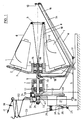
Die Fig. 1 zeigt eine erste Ausführungsform des erfindungsgemäßen Fadenzwirngeräts. In einem am Maschinengestell 4 befestigten Lagerbock 7 ist mit Hilfe der Lager 13 die Spindel 8 drehbar gelagert. Sie trägt an ihrem oberen Ende einen Spulenteller 3, der die Vorlagespule 1 trägt. Der mit Hilfe der in der Tellernabe 12 sitzenden Lager 14 auf dem einen Ende der Spindel 8 gelagerte Spulenteller 3 weist ein Gewicht 15 auf, welches bei im wesentlichen horizontem Verlauf der Spindel 8 den Spulenteller 3 ruhig stellt.1 shows a first embodiment of the thread twisting device according to the invention. In a
Die von den Vorlagespulen 1 ablaufenden Fäden 6 werden über einen konzentrisch zur Spindel 8 angeordneten Ring 5, welcher über eine Tragstange 18 mit der Nabe 12 des Spulentellers 3 verbunden ist, in Richtung auf die Spindelachse umgelenkt und treten in einen zentralen Fadenkanal 19 der Spindel 8 ein. Sie verlassen diesen hinter dem Spulenteller 3 durch eine radiale Bohrung 20 als eine erste Drehung aufweisendes Fadenbündel 9. Sie durchlaufen dann den radialen Ballonfadenführer und den Fadenballon 16 bis zum Ballonfadenführer 10 und erhalten dabei ihre zweite Drehung. Bei der dargestellten Ausführungsform wird das nun gezwirnte Garn 11 am Ballonfadenführer 10 umgelenkt und über Fadenführer 17, 21 zu einem Fadenlieferwerk geführt, welches aus dem hinteren Spindelende 31 und einer durch nicht dargestellte Mittel federnd an das Spin-. delende 31 angepreßten Anpreßrolle 35 besteht. Die Anpreßrolle ist in einer am Gehäuseteil 33 schwenkbar befestigten Gabel 34 drehbar gelagert. Vom Lieferwerk 31, 35 wird der Faden weiter zu einem Fadenspeicher 39 geführt, der in der dargestellten Ausführungsform aus einer festen Fadenführerstange 22 und einem um eine Schwenkachse 25 gegen die Wirkung einer Druckfeder 26 schwenkbaren Fadenführungshebel 23 besteht.The
Die Spindel 8 ist durch einen Motor 27 mit Hilfe einer auf der Motorachse sitzenden Riemenscheibe 28 und einer über den Riemen 30 mit ersterer verbundenen, auf der Spindel sitzenden Riemenscheibe 29 angetrieben. Im Wirkungsbereich des Fadenführungshebels 23 ist ein Mikroschalter 38 angeordnet, dessen Schaltnase 37 mit einem Plättchen 36 am Fadenführungshebel 23 zusammenwirkt. Bei entsprechend der Darstellung abgeschwenktem Fadenführungshebel 23 besteht keine Berühung zwischen Schaltnase 37 und Schaltplättchen 36, der Motor ist abgeschaltet. Wird der Garnvorrat im Gamspeicher 39 so klein, daß der Hebel 23 gegen die Feder 26 in Richtung auf dei Fadenführungsstange 22 geschwenkt wird, so wird mit Hilfe des Plättchens 36 der Mikroschalter 38 betätigt und der Motor 27 eingeschaltet. Die Spindel 8 und damit das durch ihr Ende 31 zusammen mit der Anspreßrolle 35 gebildete Lieferwerk 31, 35 setzt sich in Bewegung und fördert das Garn 11 in den Garnspeicher 39. Unter dem Druck der Feder 26 wird mit größer werdendem Garnvorrat der Fadenführungs- oder Schalthebel 23 langsam von der Fadenführungsstange 22 weggeschwenkt und gibt schließlich, bei Erreichen des vorgesehenen Garnvorrats im Fadenspeicher 39, die Schaltnase 37 frei, der Motor wird abgeschaltet.The
Bei der in der Zeichnung dargestellten Ausführungsform ist auf das hintere Spindelende 31 eine Hülse 32 aufgesetzt. Sie bildet hier zusammen mit der Anpreßrolle 35 das eigentliche Lieferwerk, da sie mit dem Spindelende 31 drehfest verbunden ist. Durch wahlweise Benutzung des Spindelendes 31 selbst als wirksame Förderoberfläche oder auf das Spindelende aufgeschobener Hülsen 32 verschiedenen Durchmessers kann das Verhältnis von Fadenfördergeschwindigkeit und Spindeldrehzahl, damit der Zwirnungsgrad, in relativ weiten Grenzen variiert werden. Bei federnd angepreßter Anordnung der Anpreßrolle 35 ist dabei im allgemeinen lediglich der Austausch der jeweiligen Hülsen 32 erforderlich. Die aufgeschobene Hülse 32 legt sich in der dargestellten Ausführungsform mit einer Stirnseite an einen Bund oder Anschlag 40 an. Zur Sicherstellung einer drehfesten Verbindung können Stirnseiten der Hülsen 32 und Bund 40 ineinanderpassende Einkerbungen aufweisen.In the embodiment shown in the drawing, a
Bei einer abgewandelten Ausführungsform entsprechend Fig. 2 tritt der aus der Spindel 8 bei 20 austretende Faden unmittelbar in einen mit der Spindel 8 verbundenen und Teil derselben bildenden Ablegerüssel 42 ein, welcher ihn im Bereich der Ballonspitze auf einen feststehenden, mit dem Maschinengestell 4 verbundenen Drehkörper 44, beispielsweise einen Zylinder oder ein Hyperboloid mittels seines Mundstücks 43 ablegt. Das Garn 16 wird auf der zur Spindel 8 weisenden Seite 46 des Rotationskörpers 44 in dessen zentrale Bohrung 49 eingeführt und als fertiges Garn 41 abgezogen.In a modified embodiment according to FIG. 2, the thread emerging from the
Bei der in Fig. 2 dargestellten Ausführungsform ist eine von der der Fig. 1 wesentlich unterschiedene Form der Fadenfördereinrichtung gewählt. Der Rotationskörper 44 ist hier zugleich Faden- oder Garnspeicher 39 und Teil der aus dem Rotationskörper 44 und dem mit der Zwirnspindel 8 als Teil von ihr umlaufenden Ablegerüssel 42 mit seinem Mundstück 43 bestehenden Fadenfördereinrichtung. In den Fig. 3 ist jeweils ein zylindrischer Rotationskörper abgebildet. Der Rotationskörper der Fig. 4 ist ein Hyperboloid, der in der Normalebene, in der er den kleinsten Durchmesser hat, abgeschnitten ist.In the embodiment shown in FIG. 2, a form of the thread conveying device that is substantially different from that of FIG. 1 is selected. The rotating
Die Veränderung des Verhältnisses von Fadengeschwindigkeit und Spindeldrehzahl kann durch Austausch des Rotationskörpers gegen solche mit unterschiedlichen wirksamen Durchmessern erfolgen. Dabei ist es bei - ggf. zur Erleichterung des Garnablaufs gewählten - nichtzylindrischen Formen wie beispielsweise der entsprechend Fig. 4 besonders angezeigt, den Abstand zwischem dem Mundstück 43 und der Oberfläche des Rotationskörpers 44 so klein wie möglich zu halten. Wie in Fig. 2 und auch in Fig. 4 gezeigt, wird das auf dem Rotationskörper 44 als Fadenspeicher 39 aufgewickelte Garn auf der zur Spindel 8 weisenden Seite in einer Schlaufe 47 in eine zentrale Bohrung 49 des Körpers 44 eingeführt und durch diese hindurch zentral abgezogen.The ratio of the thread speed to the spindle speed can be changed by exchanging the rotating body for those with different effective diameters. It is particularly advisable in the case of non-cylindrical shapes, possibly chosen to facilitate the running of the yarn, such as, for example, that shown in FIG. 4, to keep the distance between the
Die Mengenabtastung ist bei den Ausführungsformen nach den Fig. 2 bis 4 abweichend von der in Fig. 1 gezeigten ausgeführt, wenngleich auch hier ein im Motorstromkreis angeordneter Ein- und Ausschalter 38 verwandt wird. Er kann ein Mikroschalter oder ein anderes geeignetes Schaltglied sein. In die Oberfläche des Rotationskörpers 44 ist hier (s.Fig. 3) ein Schaltschlitz 50 eingearbeitet, in welchem hier eine Schaltzunge 51 sowie ein Mikroschalter 38 mit Schaltnase 37 untergebracht sind. Bei fehlender Bewicklung des Rotationskörpers 44 ragt die Schaltzunge 51 aus dem Schaltschlitz 50 heraus. Mit vom (in der Zeichnung) rechten Ende beginnender Bewicklung mit der im Ballon 16 herrschenden Fadenzugkraft wird die Schaltzunge 51, hier als geformtes Federplättchen dargestellt, stetig weiter in den Schaltschlitz 50 gedrückt, bis sie schließlich die Schaltnase 37 des Schalters 38 betätigt und den Motor 27 ausschaltet. Mit dem Abarbeiten des Garnvorrats 39 wird die Schaltzunge wieder freigegeben, was schließlich zum Wiederanschalten des Antriebs 27 führt.2 to 4 deviates from that shown in FIG. 1, although an on and off
Bei dem Ausführungsbeispiel nach Fig. 5 ist in dem Ständer 4 eine Doppeldrahtzwirnspindel 8 horizontal in Lagern 13 drehbar gelagert. Auf der Zwirnspindel 8 ist der Spulenteller 3 in Lagern 14 schwimmend gelagert. Er wird durch Gewicht 15, das rotationsunsymmetrisch angebracht ist, in seiner Lage schwimmend gehälten. Auf dem Spulenteller 3 sind eine Vielzahl von Spulenhaltern 2, beispielsweise Dorne befestigt. Auf diesen Dornen werden Vorlagespulen 1 mit Garnen unterschiedlicher Farben aufgesteckt. In Fig. 5 sind zwei solcher Vorlagespulen gezeigt. An der Nabe 12 des Spulentellers ist eine achsparellele Stange 18 befestigt. Am Ende der Stange 18 sitzt der Ablauffadenführer 5, der die Form eines Rings hat, zentrisch zur Spindel. Die Spindel ist mit einer Zentralbohrung 19 ausgestattet, die sich durch die Lagerung 14 erstreckt und dahinter in radiale Richtung abbiegt und sodann in einem radialen Ballonfadenführer 56 endet. Der Ballonfadenführer 56 erstreckt sich im wesentlichen in radialer Richtung und ist hier als geschlitztes Rohr (in Fig. 1 als radiale Stange mit Umlenkaugen) ausgeführt.In the embodiment according to FIG. 5, a double-
Auf der anderen Seite der Spindel und zentrisch über der Spindel sitzt der ortsfeste Ballonfadenführer 10. Diesem ist ein Fadenförderwerk 32 in Form einer drehbar angetriebenen Rolle vorgeordnet. Anpreßrolle 35 wird durch eine Feder gegen die Rolle des Förderwerks 32 gedrückt.The stationary
Der Rolle des Fadenförderwerks 32 ist eine Riemenscheibe 58 formschlüssig aufgesetzt. Ein Fadenführer 17, der ortsfest angeordnet ist, dient dem Zweck den Faden auf den Fadenspeicher 39 zu lenken. Der Fadenspeicher 39 besteht aus zwei nebeneinander in einer gemeinsamen Ebene angeordneten Stangen 22 und 23, die eine Relativbewegung zueinander im Sinne einer Änderung ihres Abstandes machen können. Hierzu ist die Stange 23 als Schwenkhebel ausgeführt und um Schwenklager 25 schwenkbar. Die Andere Stange 22 ist starr auskragend gelagert. Das Lagerende des Schwenkhebels 23 besitzt einen Schaltnocken 36, der mit der Schaltnase 37 eines ortsfesten Schalters 38 zusammenwirkt.A
Das Spindelende 31 ist hohl. Mit dem Spindelende sind Riemenscheiben 29 mit unterschiedlichen Durchmessers formschlüssig verbindbar. Hierzu besitzen die Riemenscheiben 29 ein Lagezapfen 57, der in das hohle Spindelende 31 paßt und darin axial und in Umfangsrichtung formschlüssig einklemmbar ist.The
Durch Motor 27 und Welle 60 werden einerseits die Spindel über Treibriemen 30 und Riemenscheibe 29 und andererseits das Fadenförderwerk 32 über Treibriemen 59 und Riemenscheibe 38 synchron angetrieben. Dabei kann das Drehzahlverhältnis durch Wahl einer Riemehscheibe 29 mit gewünschtem Durchmesser für das Spindelende 31 bestimmt werden.
Im Betrieb werden mehrere Vorlagespulen 1 auf den Spulenhalter aufgesteckt. Die Fäden werden sodan in einem gefalteten Fadenlauf durch den Ablauffadenführer 5, sodann durch den Fadenkanal 19 der Spindel auf der Spindelachse, sodann durch den Ballonfadenführer 56 mit seinen entsprechenden Umlenkungen radial nach außen und sodann wieder neben der Spindelachse zurück durch den Ballonfadenführer 10 geführt und in das Förderwerk 32 eingelegt. Sodann wird der Faden über den ortsfesten Fadenführer 17 in den Bereich des Einspannendes der Stangen 22, 23 geführt und mehrfach beispielsweise zweifach- um die Stangen 22 und 23 des Fadenspeichers 39 geschlungen, der Faden verläßt den Fadenspeicher durch die Fadenaugen 62, 63 am Ende der Stangen 22 bzw. 23 Der Faden wird nun beispielsweise an eine Handstrickmaschine oder einen von Hand betriebenen Knäuelwickler (nicht dargestellt) gelegt. Wenn nun die Handstrickmaschine oder der Knäuelwickler in Gang gesetzt wird oder wenn die Strickerin zum Handstricken Faden braucht und der Faden in Pfeilrichtung 64 abgezogen wird, so verringert sich die Fadenlänge, mit der der Faden die Stangen.22 und 23 umschlingt. Dadurch wird die Stange 23 (Schwenkhebel) verschwenkt, bis der Schaltnocken 36 in Kontakt mit der Schaltnase 37 des Mikroschalters kommt. Nun wird der Motor eingeschaltet und das Förderwerk 32 und die Spindel 8 werden synchron in Gang gesetzt. Durch das Förderwerk wird der Faden von der Vorlagespulen 1 abgezogen. Durch Drehung der Spindel 8 mit dem Ballonfadenführer 56 bildet der Faden einen Ballon 16 zwischen dem Ausgang des Ballonfadenführers 56 und dem Ballonfadenführer 10. Der Faden wird verzwirnt und gleichzeitig zunächst in den Fadenspeicher 39 gefördert, wobei der Schwenkhebel 23, der federbelastet oder - wie im ausgeführten Beispiel gezeigt - durch Gewicht 65 belastet ist, derart verschwenkt, daß sich der Abstand zwischen der ortsfesten Stange 22 und dem Schwenkhebel 23 vergrößert. Es wird damit mehr Fadenmenge in dem Fadenspeicher 39 gespeichert bzw. es wird nunmehr der anfallende Faden zum direkten Verbrauch mit Pfeilrichtung 64 zur Verfügung gestellt. Der Speicher 39 wirkt hierbei als Materialpuffer. Gleichzeitig wirkt der Fadenspeicher 39 als Meßeinrichtung für den Fadenverbrauch und die Fadenzufuhr und damit als Regelglied in einem Zweipunkt-Regelkreis, durch den die Bereitstellung gezwirnten Fadens auf den Verbrauch eingeregelt wird. Schwankungen in der Verarbeitungsgeschwindigkeit werden durch die Schwenkbewegungen des Schwenkhebels 23 ausgeglichen. Bei Beendigung des Verbrauchs werden Zwirnung und Förderung unterbrochen, wenn der Speicher seine durch die relative Anordnung des Schalters 38 vorgegebene Füllung erreicht hat. Durch Austausch einer oder mehrer Vorlagespulen 1 kann die farbliche Zusammensetzung des fertigen Fadens jederzeit geändert werden.In operation,
Claims (18)
Priority Applications (1)
| Application Number | Priority Date | Filing Date | Title |
|---|---|---|---|
| AT87105009T ATE53611T1 (en) | 1986-04-11 | 1987-04-04 | THREAD TWISTING DEVICE. |
Applications Claiming Priority (4)
| Application Number | Priority Date | Filing Date | Title |
|---|---|---|---|
| DE19863612321 DE3612321A1 (en) | 1986-04-11 | 1986-04-11 | Thread-twisting appliance |
| DE3612321 | 1986-04-11 | ||
| DE3635460 | 1986-10-18 | ||
| DE19863635460 DE3635460A1 (en) | 1986-10-18 | 1986-10-18 | Thread-twisting appliance |
Publications (3)
| Publication Number | Publication Date |
|---|---|
| EP0240956A2 EP0240956A2 (en) | 1987-10-14 |
| EP0240956A3 EP0240956A3 (en) | 1988-02-10 |
| EP0240956B1 true EP0240956B1 (en) | 1990-06-13 |
Family
ID=25842836
Family Applications (1)
| Application Number | Title | Priority Date | Filing Date |
|---|---|---|---|
| EP87105009A Expired - Lifetime EP0240956B1 (en) | 1986-04-11 | 1987-04-04 | Apparatus for twisting yarns |
Country Status (3)
| Country | Link |
|---|---|
| US (1) | US4754599A (en) |
| EP (1) | EP0240956B1 (en) |
| DE (1) | DE3763202D1 (en) |
Families Citing this family (7)
| Publication number | Priority date | Publication date | Assignee | Title |
|---|---|---|---|---|
| US4848078A (en) * | 1988-07-05 | 1989-07-18 | White Frances H | Flyer for textile apparatus |
| US5622039A (en) * | 1994-04-08 | 1997-04-22 | Ceeco Machinery Manufacturing Limited | Apparatus and method for the manufacture of uniform impedance communications cables for high frequency use |
| US5564268A (en) * | 1994-04-08 | 1996-10-15 | Ceeco Machinery Manufacturing Ltd. | Apparatus and method for the manufacture of uniform impedance communication cables for high frequency use |
| DE4431830C1 (en) * | 1994-09-07 | 1995-10-26 | Palitex Project Co Gmbh | Method for piecing a thread in a device for producing a thread in an integrated spinning-twisting process and device for carrying out the method |
| DE202015007655U1 (en) * | 2015-11-06 | 2015-11-23 | Saurer Germany Gmbh & Co. Kg | cabling spindle |
| CN105374270B (en) * | 2015-11-23 | 2017-12-05 | 吕畅宇 | Middle school's electrostatic precipitation is around yarn apparatus for demonstrating |
| CN111876864A (en) * | 2020-08-14 | 2020-11-03 | 东台远欣机械有限公司 | Adjustable safety wire guiding device for twisting machine |
Family Cites Families (16)
| Publication number | Priority date | Publication date | Assignee | Title |
|---|---|---|---|---|
| DE568191C (en) * | 1933-01-16 | Adolf Meyer | Two-for-one twisting spindle | |
| DE812574C (en) * | 1944-10-01 | 1951-09-03 | Glanzstoff Ag | Process and two-for-one twisting spindle for the production of twisted rayon |
| US2586123A (en) * | 1951-01-23 | 1952-02-19 | American Viscose Corp | Uniform strand tension device |
| US2586038A (en) * | 1951-01-23 | 1952-02-19 | American Viscose Corp | Uniform strand tension device |
| US2728185A (en) * | 1952-03-01 | 1955-12-27 | Alfred W Vibber | Twisting spindle balloon control |
| US2732680A (en) * | 1953-03-12 | 1956-01-31 | vibber | |
| US2871648A (en) * | 1957-11-04 | 1959-02-03 | Alfred W Vibber | Twisting spindle balloon control |
| US3172247A (en) * | 1959-10-05 | 1965-03-09 | Textile & Chem Res Co Ltd | Double twist cabling apparatus |
| FR1294927A (en) * | 1961-04-21 | 1962-06-01 | Rop Bureau | Flow regulator for textile yarn |
| US3238711A (en) * | 1963-11-12 | 1966-03-08 | Western Electric Co | Wire depletion control for wire twisting apparatus |
| US3295304A (en) * | 1964-09-09 | 1967-01-03 | Apparatus for twisting and plying strands | |
| US3499277A (en) * | 1967-06-06 | 1970-03-10 | Alfred W Vibber | Apparatus for twisting and plying strands |
| DE2015668A1 (en) * | 1969-04-05 | 1970-10-15 | Weisse, Johannes, Mailand (Italien) | Twisting machine for knitting yarn |
| JPS5551046B2 (en) * | 1972-05-26 | 1980-12-22 | ||
| FR2455644A1 (en) * | 1979-05-04 | 1980-11-28 | Asa Sa | DEVICE FOR TWISTING A YARN BY DOUBLE TORSION |
| DE3015044A1 (en) * | 1980-04-18 | 1981-10-29 | HAMEL GmbH Zwirnmaschinen, 4400 Münster | DOUBLE WIRE TWISTING DEVICE |
-
1987
- 1987-04-04 EP EP87105009A patent/EP0240956B1/en not_active Expired - Lifetime
- 1987-04-04 DE DE8787105009T patent/DE3763202D1/en not_active Expired - Fee Related
- 1987-04-07 US US07/035,372 patent/US4754599A/en not_active Expired - Fee Related
Also Published As
| Publication number | Publication date |
|---|---|
| DE3763202D1 (en) | 1990-07-19 |
| EP0240956A3 (en) | 1988-02-10 |
| EP0240956A2 (en) | 1987-10-14 |
| US4754599A (en) | 1988-07-05 |
Similar Documents
| Publication | Publication Date | Title |
|---|---|---|
| DE944884C (en) | Method and device for twisting a thread bundle and for winding the twisted thread bundle into a winding, in particular in rayon spinning machines | |
| EP2122022B1 (en) | Ring spinning machines with device for supplying flames | |
| EP0729524A1 (en) | Spinning winding frame | |
| DE2227903C3 (en) | Device for producing or treating textile yarn | |
| EP0240956B1 (en) | Apparatus for twisting yarns | |
| DE3926227C2 (en) | ||
| EP0696656B1 (en) | Procedure and device for producing a twisted yarn | |
| DE102018008486A1 (en) | Workstation of a double twisting machine or cabling machine for the production of carpet yarn | |
| DE2831506C2 (en) | ||
| CH630129A5 (en) | SPOILER. | |
| DE3635460A1 (en) | Thread-twisting appliance | |
| DE3122385C2 (en) | Device for winding up yarn | |
| AT205893B (en) | Device for twisting continuous fiber yarn | |
| EP0768413A1 (en) | Thread furnishing device for textile machines | |
| DE170853C (en) | ||
| DE4235433A1 (en) | Method and device for producing a twisted thread | |
| WO2005026419A1 (en) | Textile machine comprising a compression drafting system | |
| DE3139394C2 (en) | ||
| WO2023247243A1 (en) | Apparatus for rewinding yarns | |
| DE3612321A1 (en) | Thread-twisting appliance | |
| EP0190272A1 (en) | Twining machine | |
| AT126827B (en) | Kreuzkötzer made of artificial silk and device for making the same. | |
| DE1710019A1 (en) | Method for twisting threads or yarns and twisting machine | |
| CH542778A (en) | Thread reservoir - eg for shuttleless loom, has stationary, cone-ended drum | |
| DE1923847A1 (en) | Method and yarn winding machine for producing yarn packages |
Legal Events
| Date | Code | Title | Description |
|---|---|---|---|
| PUAI | Public reference made under article 153(3) epc to a published international application that has entered the european phase |
Free format text: ORIGINAL CODE: 0009012 |
|
| AK | Designated contracting states |
Kind code of ref document: A2 Designated state(s): AT BE CH DE ES FR GB IT LI LU NL SE |
|
| PUAL | Search report despatched |
Free format text: ORIGINAL CODE: 0009013 |
|
| AK | Designated contracting states |
Kind code of ref document: A3 Designated state(s): AT BE CH DE ES FR GB IT LI LU NL SE |
|
| 17P | Request for examination filed |
Effective date: 19880615 |
|
| 17Q | First examination report despatched |
Effective date: 19890922 |
|
| GRAA | (expected) grant |
Free format text: ORIGINAL CODE: 0009210 |
|
| AK | Designated contracting states |
Kind code of ref document: B1 Designated state(s): AT DE |
|
| REF | Corresponds to: |
Ref document number: 53611 Country of ref document: AT Date of ref document: 19900615 Kind code of ref document: T |
|
| REF | Corresponds to: |
Ref document number: 3763202 Country of ref document: DE Date of ref document: 19900719 |
|
| EN | Fr: translation not filed | ||
| PG25 | Lapsed in a contracting state [announced via postgrant information from national office to epo] |
Ref country code: AT Effective date: 19910404 |
|
| PLBE | No opposition filed within time limit |
Free format text: ORIGINAL CODE: 0009261 |
|
| STAA | Information on the status of an ep patent application or granted ep patent |
Free format text: STATUS: NO OPPOSITION FILED WITHIN TIME LIMIT |
|
| 26N | No opposition filed | ||
| PG25 | Lapsed in a contracting state [announced via postgrant information from national office to epo] |
Ref country code: DE Effective date: 19920201 |