EP0240945B1 - Induktionsmotor - Google Patents
Induktionsmotor Download PDFInfo
- Publication number
- EP0240945B1 EP0240945B1 EP87104944A EP87104944A EP0240945B1 EP 0240945 B1 EP0240945 B1 EP 0240945B1 EP 87104944 A EP87104944 A EP 87104944A EP 87104944 A EP87104944 A EP 87104944A EP 0240945 B1 EP0240945 B1 EP 0240945B1
- Authority
- EP
- European Patent Office
- Prior art keywords
- stator
- slots
- induction motor
- rotor
- torque
- Prior art date
- Legal status (The legal status is an assumption and is not a legal conclusion. Google has not performed a legal analysis and makes no representation as to the accuracy of the status listed.)
- Expired
Links
Images


Classifications
-
- H—ELECTRICITY
- H02—GENERATION; CONVERSION OR DISTRIBUTION OF ELECTRIC POWER
- H02K—DYNAMO-ELECTRIC MACHINES
- H02K17/00—Asynchronous induction motors; Asynchronous induction generators
- H02K17/02—Asynchronous induction motors
- H02K17/16—Asynchronous induction motors having rotors with internally short-circuited windings, e.g. cage rotors
-
- H—ELECTRICITY
- H02—GENERATION; CONVERSION OR DISTRIBUTION OF ELECTRIC POWER
- H02K—DYNAMO-ELECTRIC MACHINES
- H02K1/00—Details of the magnetic circuit
- H02K1/06—Details of the magnetic circuit characterised by the shape, form or construction
- H02K1/12—Stationary parts of the magnetic circuit
- H02K1/16—Stator cores with slots for windings
-
- H—ELECTRICITY
- H02—GENERATION; CONVERSION OR DISTRIBUTION OF ELECTRIC POWER
- H02K—DYNAMO-ELECTRIC MACHINES
- H02K1/00—Details of the magnetic circuit
- H02K1/06—Details of the magnetic circuit characterised by the shape, form or construction
- H02K1/22—Rotating parts of the magnetic circuit
- H02K1/26—Rotor cores with slots for windings
-
- H—ELECTRICITY
- H02—GENERATION; CONVERSION OR DISTRIBUTION OF ELECTRIC POWER
- H02K—DYNAMO-ELECTRIC MACHINES
- H02K2201/00—Specific aspects not provided for in the other groups of this subclass relating to the magnetic circuits
- H02K2201/06—Magnetic cores, or permanent magnets characterised by their skew
Definitions
- the present invention relates to an induction motor and, more particularly, to a highly precise variable speed servo induction motor operated in the wide speed range.
- induction motors have been used as low-cost, rough constant-speed motors.
- induction motors have been used as highly precise variable speed servo motors.
- Servo motors must be smoothly operated in a low-speed range including zero speed.
- the performance of the induction motor from the viewpoint of an object to be driven is determined by the induction motor itself and a variable frequency power source (to be referred to as a driver hereinafter) for applying electrical energy to the induction motor.
- the frequency of the variable frequency power source is called a primary frequency since the energy is applied to the primary winding of the induction motor. This frequency is represented by f1.
- Such a torque ripple is regarded to be caused by the driver.
- Recent drivers have been improved due to developments of electronic devices (e.g., LSIs and power-controlled semiconductors), current, speed and position detectors, and software techniques for achieving highly precise high-speed data processing.
- a electric current having substantially a sinusoidal wave can be supplied from the driver to the induction motor in the wide variable frequency range.
- the induction motor serves as a servo motor driven at a very low speed below the frequency f1 (below several Hz)
- the torque ripple of the 6kf1 harmonic component is not generated by the driver but by the induction motor. Therefore, it is indispensable to eliminate the torque ripple generated by the induction motor itself.
- a balanced, half-pitched capacitor induction motor comprises a stator core member with equally spaced teeth equal in number to twice the number of motor poles and with the inner ends of the teeth having equal angular extend, and a squirrel cage rotor member.
- the main field winding comprises serially connected coils equal in number to the number of motor poles respectively embracing alternate, consecutive ones of the teeth and being adapted to be connected across a single phase source of alternating current.
- An auxiliary field winding comprises serially connected coils embracing consecutive teeth intermediate the teeth having the main winding coils thereon, the auxiliary winding coils being serially connected with a phase-displacing capacitor across the serially connected main winding coils.
- the main and auxiliary windings have equal ampere turns and equal pitch thereby providing a balanced, half-pitch two phase motor winding.
- the rotor member has its squirrel cage bars spiralled by one-tenth of a full turn, i.e. two pole pitches of the 5th harmonic or 36° to eliminate the fifth harmonic in the speed torque curve. Since this known motor includes a capacitor, it is effective for only a predetermined primary frequency operation. More specifically, the torque ripple is increased in other primary frequency operations, sound noise is increased, and efficiency is degraded. This motor is suitable for only the conventional operation at almost a constant speed.
- EP-A-0 239 988 which has been published after the filing date of the present application relates to the three-phase induction motor.
- This document deals with the problem that the magnetic flux generated in an air gap between a stator core and a rotor core includes odd harmonic components especially the fifth and the seventh harmonic components which adversely effect to generate a torque ripple.
- a conductor groove of a rotor core is skewed by an electrical angle 2 ⁇ /n.
- a three-phase induction motor for variable speed operation including a stator having slots for accommodating a primary winding therein, the stator being adapted to generate a rotary magnetic flux upon application of electrical energy to the primary winding, and a rotor or a moving element having slots for accommodating a secondary winding consisting of coils or a squirrel-cage circuit, the induction motor being adapted to cause the rotor to generate a torque or a thrust by a magnetic flux crossing the secondary winding and a secondary current when the electrical energy is applied to the induction motor to cause electromagnetic induction in the stator and to supply the secondary current to the secondary winding, wherein the stator slots are skewed relative to the rotor slots and a skew amount is an integer multiple of a stator electrical angle of 60°, thereby minimizing a torque ripple which is an integer multiple of six times of the primary frequency of the electrical energy.
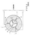
- Fig. 1 is a sectional view showing the principle of a general induction motor.
- the induction motor comprises a stator 2 having slots for accommodating a primary winding 1 therein and a rotor 4 having slots for accommodating a secondary winding 3.
- a primary current supplied to the primary winding is represented by I1 (vector).
- the primary current consists of an excitation current I0 (vector).
- a secondary current induced in the secondary winding 3 is represented by I2 (vector).
- a rotary magnetic flux ⁇ 2 (vector) is generated in a gap 5 between the stator 2 and the rotor 4.
- the rotary magnetic flux and the secondary current I2 cause the rotor 4 to generate the torque TG in the same principle as in an Arago disk.
- the causes of the torque ripple ⁇ T included in the torque TG are an unbalance of the power source, a circuitry unbalance of the primary winding 1 of the induction motor, and a circuitry unbalance of the secondary winding 3 of the induction motor.
- the unbalance of the power source can be eliminated by improving the driver.
- the unbalances of the primary and secondary windings can be eliminated by using the induction motor within the limits of its ratings.
- the frequency of electrical vibrations and electromagnetic noise of the induction motor is twice the frequency (fundamental wave) f1 of the primary current I1 or twice the slip frequency fs.
- the torque ripple ⁇ T can be analyzed such that the frequencies of the harmonic torque ⁇ T are 6 times, 12 times, 18 times,... the frequency f1 of the primary current I1.
- a sinusoidal PWM (Pulse Width Modulation) output is used in the driver, a sinusoidal wave can be obtained wherein the waveform of the primary current I1 is greatly improved. Therefore, the above-mentioned steady torque ripple ⁇ T can be eliminated according to this analysis.
- I2 -(M/R2) ⁇ (d/dt + jWs)I0 (3)
- M the mutual inductance between the primary and secondary windings of the induction motor
- R2 is the resistance of the secondary winding
- j is an operator representing an orthogonal relationship.
- R2 and M may be regarded as constants although they depend on temperature changes.
- the magnetic flux ⁇ 2 and the secondary current I2, both of which include harmonic components, are represented by ⁇ 2 and I 2, respectively.
- the primary winding 1 comprises a limited number of coils, and its spatial disposition is represented by a simple concentrated winding including many harmonic components, a distributed winding including a small number of harmonic components, or a distributed fractional-pitch winding.
- electromotive force components a total of these components is proportional to the magnetic flux ⁇ 2, excluding the variations caused by the stator slots
- the magnetic flux ⁇ 2 is regarded to include the space harmonic components corresponding to the rectangular waveform. Therefore, the excitation current I 0 corresponding to the magnetic flux ⁇ 2 include the space harmonic components accordingly.
- the quantitative expression of the excitation current I0 will be made. Assume that the induction motor is a 3-phase motor. Three identical coils A, B, and C arranged to be spatially (i.e., electrical angle) 120° out of phase constitute the primary winding 1.
- the excitation currents supplied to the coils A, B, and C are defined as ioa , iob , and ioc , respectively.
- These excitation currents include harmonic components Tp (p ⁇ 1) corresponding to the time harmonic components and are represented as follows. where ⁇ is the angular frequency corresponding to the primary frequency.
- the excitation current I 0 further includes the space harmonic components Sn (n ⁇ 1) and is defined as follows:
- the 6th harmonic components are confirmed for ⁇ t and ⁇ .
- Equations (14) and (15) represent: 6th order ⁇ t...time harmonic components 6th order ⁇ ...space harmonic components.
- the primary current I1 is a sinusoidal wave current, i.e., the current I1 does not contain the time harmonic components
- the magnetic flux ⁇ 2 and the secondary current I 2 which include the 6th space harmonic components corresponding to Tp or Tq excluding T1 in equation (13) or to zero in equation (13) must be taken into consideration.
- the primary current I 1 include the time harmonic components
- the 6th time harmonic components must be considered in the same manner as in the conventional case.
- the value of coefficient Sn in equation (13) is determined by the primary winding and is decreased in an order of a concentrated winding, a distributed winding, and a distributed fractional-pitch winding. However, since the limited number of coils of the primary winding are fitted in the corresponding number of slots, the improvement is limited.
- the Tp value is determined by the harmonic component of the primary current I1 and can be greatly decreased by an improvement of the primary current I1.
- the induction motor itself in order to reduce the influence of the space harmonic components to reduce the torque ripple components ⁇ T, the induction motor itself must be improved.
- a countermeasure for reducing the 6th space harmonic components can also serve as the one for reducing the 6th time harmonic components.
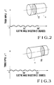
- Fig. 3 shows the relationship between the electrical angle and the torque ripple ⁇ T on another cross section 22 phase-shifted from the cross section 21. Even if the torque ripple is present but if the two cross sections 21 and 22 of the torque ripples are 180° out of phase, the torque ripple component ⁇ T on the cross section 21 is cancelled with the torque ripple component ⁇ T on the cross section 22. This idea is applied to shift the phases of the torque ripple components generated on the respective cross sections of the rotor.
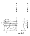
- Fig. 4A is a developed view wherein the rotor 6 is developed by a stator electrical angle of 60°.
- the horizontal direction in Fig. 4A represents the rotational direction.
- the torque ripple curves X1, X2 and X3 are represented to be Y1, Y2, Y3, and Y4 along the axial direction of the rotating shaft.
- the curves Y1, Y2, Y3, and Y4 correspond to angular positions given by rotational angles ⁇ 1, ⁇ 2, ⁇ 3, and ⁇ 4, respectively, as shown in Fig. 4B.
- the integrated value is the one of the one period of the torque ripple components, i.e., zero at all rotational angles ⁇ , as shown in Fig. 4B.
- Figs. 5A and 5B show a case wherein the phase shift amount is an electrical angle of 30° not to satisfy condition (16) in correspondence with the case of Figs. 4A and 4B.
- Reference symbols X1', X2', and X3' denote torque ripple curves on the cross sections, respectively; and Y1', Y2', and Y3', torque ripple curves at angular positions corresponding to angles ⁇ 1, ⁇ 2, and ⁇ 3, respectively.
- the integrated value of the torque ripple components ⁇ T is not zero (Fig. 5B) unlike in the case of Fig. 4B.
- phase shift amount is an integer multiple of the electrical angle of 60° in condition (16)
- An integrated value of the torque ripple components up to the axial length L at any angular position ( ⁇ ) becomes zero.
- phase shifting of the torques generated on the respective cross sections of the rotor is achieved by a technique so-called skewing in the conventional method.
- One of the skew methods in conventional induction motors is to incline the stator slots by one slot pitch with respect to the rotor slots.
- An expected effect is to reduce the influence of the so-called slot harmonic components.
- the torque ripple by th slot harmonic components is not included in equations (14) and (15).
- the skew amount is set to be 360°/n when n is the order of the specific harmonic component of the primary current with respect to the electrical angle of 360°.
- An expected effect is to eliminate the influence of the nth harmonic component of the primary current.
- S5 is zero in equation (13).
- the component associated with S5 in equation (13) can be improved, but many ripple components by other elements are present according to the experimental results. If the value of 360°/n differs from one pitch of the stator slots, the torque ripple caused by the slot harmonic components often appears distinctly.
- the skew amount in the induction motor according to the present invention does not depend on the stator slot pitch or the order of the specific harmonic component of the primary current but can be determined by only condition (16).
- Skewing is performed in the present invention, as in the conventional induction motor. Accordingly, as compared with the structure of the conventional induction motor employing conventional skewing, the structure of the induction motor according to the present invention can be simply provided without any difficulty.
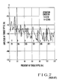
- Fig. 7 shows a torque spectrum of an induction motor when the stator of the induction motor of Fig. 6 is used and the skew amount of the rotor slots is given as one slot pitch as in the conventional case.
- the conditions of f1 and fs are the same as those in Fig. 6.
- the hatched and cross-hatched portions are regarded as the influences (multiples of 15 Hz and 50 Hz) of the spectral detector of Fig. 8. Therefore, the influences must be reduced from the spectra shown in Figs. 6 and 7.
- the skew amount of the induction motor according to the present invention is determined by condition (16) but does not depend on the number of stator poles, the slot pitch of the stator, and the number of slots in the stator. Therefore, the number of slots of the stator may be an integer number for an electrical angle of 60°, depending on the number of slots of the stator. In this case, the skew amount according to the present invention is applied to remove the torque ripple components caused by the stator slots.
- Table I shows technical data of different induction motors.
- p represents the number of poles of the stator
- q represents the number of slots per pole and per phase of the stator
- r represents the skew amount figured out as the slot pitch.
- a stator winding for satisfying the above slot requirements is a so-called concentrated winding.
- the skew amount is determined to be an integer multiple of stator slot pitch to minimize the torque ripple component which is an integer multiple of six times the primary frequency f1 as well as the torque ripple component caused by the slots.
- the skew amount (i.e., an electrical angle) of the induction motor of the present invention is reduced in inverse proportion to the number of poles. Therefore, the skew amount of the induction motor of the present invention can be 120° or 180° in place of the electrical angle of 60° within the limit of condition (16).
- one of the stator and rotor slots may be parallel to the rotational axis, and the other one may be inclined with respect thereto since skewing indicates inclination of the rotor slots with respect to the stator slots.
- the present invention may be applied to the linear induction motor.
- an induction motor which minimizes the torque ripple and which can be suitably applied as a highly precise servo motor driven in the wide variable speed range.
Landscapes
- Engineering & Computer Science (AREA)
- Power Engineering (AREA)
- Control Of Ac Motors In General (AREA)
- Induction Machinery (AREA)
Claims (4)
- Dreiphaseninduktionsmotor zum Betrieb mit variabler Geschwindigkeit, der aufweist: einen Stator (2) mit Schlitzen zum Aufnehmen einer Primärwicklung (1), wobei der Stator (2) geeignet ist, einen Drehmagnetfluß beim Anlegen elektrischer Energie an die Primärwicklung (1) zu erzeugen, und einen Rotor (4) oder ein Bewegungselement mit Schlitzen zum Aufnehmen einer Sekundärwicklung (3), die aus Spulen oder einer Kurzschlußläuferschaltung besteht, wobei der Induktionsmotor geeignet ist, den Rotor zu veranlassen, ein Drehmoment oder einen Schub mittels eines die Sekundärwicklung (3) kreuzenden magnetischen Flusses und einen Sekundärstrom zu erzeugen, wenn elektrische Energie an den Induktionsmotor angelegt wird, eine elektromagnetische Induktion in dem Stator (2) zu verursachen und den Sekundärstrom an die Sekundärwicklung (3) zu liefern, wobei die Statorschlitze relativ zu den Rotorschlitzen schräg verlaufen und das Schrägmaß ein ganzzahliges Vielfaches des elektrischen Statorwinkels von 60° ist, wodurch eine Drehmomentwelligkeit minimiert wird, die ein ganzzahliges Vielfaches von der sechsfachen Primärfrequenz der elektrischen Energie ist.
- Motor nach Anspruch 1, wobei die Statorschlitze parallel zu einer axialen Richtung einer Drehwelle verlaufen (eine Richtung senkrecht zu einer Bewegungsrichtung des Bewegungselements), und nur die Rotor (die Bewegungselement)-Schlitze entlang der axialen Richtung abgeschrägt sind.
- Motor nach Anspruch 1, wobei die Rotor (die Bewegungselement)-Schlitze parallel zu einer axialen Richtung einer Drehwelle sind (eine Richtung senkrecht zu einer Bewegungsrichtung des Bewegungselements) und nur die Statorschlitze entlang der axialen Richtung abgeschrägt sind.
- Motor nach einem der Ansprüche 1, 2 und 3, wobei das Schrägmaß gleich eines ganzzahligen Vielfachen einer Statorschlitzteilung ist, wobei eine durch die Schlitze verursachte Drehmomentwelligkeit und auch die Drehmomentwelligkeit, die ein ganzzahliges Vielfaches von der sechsfachen Primärfrequenz ist, minimiert wird.
Applications Claiming Priority (2)
| Application Number | Priority Date | Filing Date | Title |
|---|---|---|---|
| JP77839/86 | 1986-04-04 | ||
| JP61077839A JPS6323539A (ja) | 1986-04-04 | 1986-04-04 | 誘導電動機 |
Publications (3)
| Publication Number | Publication Date |
|---|---|
| EP0240945A2 EP0240945A2 (de) | 1987-10-14 |
| EP0240945A3 EP0240945A3 (en) | 1988-10-19 |
| EP0240945B1 true EP0240945B1 (de) | 1992-06-10 |
Family
ID=13645215
Family Applications (1)
| Application Number | Title | Priority Date | Filing Date |
|---|---|---|---|
| EP87104944A Expired EP0240945B1 (de) | 1986-04-04 | 1987-04-03 | Induktionsmotor |
Country Status (5)
| Country | Link |
|---|---|
| US (1) | US4871934A (de) |
| EP (1) | EP0240945B1 (de) |
| JP (1) | JPS6323539A (de) |
| CN (1) | CN1007859B (de) |
| DE (1) | DE3779687T2 (de) |
Families Citing this family (19)
| Publication number | Priority date | Publication date | Assignee | Title |
|---|---|---|---|---|
| JPH03106869U (de) * | 1990-02-16 | 1991-11-05 | ||
| JP2672178B2 (ja) * | 1990-05-15 | 1997-11-05 | ファナック株式会社 | 同期電動機のロータ構造 |
| US5065590A (en) * | 1990-09-14 | 1991-11-19 | Williams International Corporation | Refrigeration system with high speed, high frequency compressor motor |
| FI90604C (fi) * | 1991-02-07 | 1994-02-25 | Kone Oy | Epätahtimoottori ja menetelmä epätahtimoottorin staattorin ja/tai roottorin valmistamiseksi |
| US5652493A (en) * | 1994-12-08 | 1997-07-29 | Tridelta Industries, Inc. (Magna Physics Division) | Polyphase split-phase switched reluctance motor |
| JP3691345B2 (ja) * | 2000-05-25 | 2005-09-07 | 三菱電機株式会社 | 永久磁石型電動機 |
| US6853105B2 (en) * | 2000-05-25 | 2005-02-08 | Mitsubishi Denki Kabushiki Kaisha | Permanent magnet motor |
| US6707209B2 (en) * | 2000-12-04 | 2004-03-16 | Emerson Electric Co. | Reduced cogging torque permanent magnet electric machine with rotor having offset sections |
| US6597078B2 (en) | 2000-12-04 | 2003-07-22 | Emerson Electric Co. | Electric power steering system including a permanent magnet motor |
| US6559654B2 (en) * | 2001-03-29 | 2003-05-06 | General Electric Company | Method and system for automatic determination of inductance |
| JP4595250B2 (ja) * | 2001-06-08 | 2010-12-08 | 三菱電機株式会社 | 単相誘導電動機 |
| CN1929260A (zh) * | 2003-07-29 | 2007-03-14 | 发那科株式会社 | 电机及电机制造装置 |
| US20050113216A1 (en) * | 2003-10-07 | 2005-05-26 | Wei Cheng | Belt drive system with outer rotor motor |
| CN102046088A (zh) * | 2008-06-02 | 2011-05-04 | 皇家飞利浦电子股份有限公司 | 用于计算机断层成像机架的变压器 |
| US8008798B2 (en) * | 2009-12-23 | 2011-08-30 | General Electric Company | Wind turbine drivetrain system |
| CN102403855B (zh) * | 2011-10-12 | 2013-11-20 | 泰豪科技股份有限公司 | 一种同步发电机正弦双迭绕组 |
| FR3032313B1 (fr) | 2015-01-29 | 2018-10-26 | Eomys Engineering | Reduction des nuisances vibratoires et accoustiques d'une machine asynchrone |
| US10141804B2 (en) * | 2017-01-11 | 2018-11-27 | Infinitum Electric Inc. | System, method and apparatus for modular axial field rotary energy device |
| JP2018207632A (ja) * | 2017-06-01 | 2018-12-27 | 株式会社東芝 | 電動機 |
Family Cites Families (10)
| Publication number | Priority date | Publication date | Assignee | Title |
|---|---|---|---|---|
| US606912A (en) * | 1898-07-05 | blathy | ||
| US1841122A (en) * | 1930-06-14 | 1932-01-12 | Gen Electric | Squirrel cage induction machine |
| DE1060474B (de) * | 1957-12-05 | 1959-07-02 | Kurt Westphalen | Kurzschlusslaeufer |
| US3013168A (en) * | 1959-04-20 | 1961-12-12 | Charles E Ellis | Suprasynchronous motor |
| US3671789A (en) * | 1971-01-19 | 1972-06-20 | Canadian Patents Dev | Synchronous reluctance motors having rotor segments of extended pole span |
| JPS5247121A (en) * | 1975-10-11 | 1977-04-14 | Mazda Motor Corp | Suction device of multiple cylinder engine |
| JPS54134309A (en) * | 1978-04-10 | 1979-10-18 | Nippon Soken | Ac power generator for vehicles |
| US4371802A (en) * | 1980-06-12 | 1983-02-01 | Morrill Wayne J | Half-pitch capacitor induction motor |
| DE3311486A1 (de) * | 1983-03-29 | 1984-10-04 | Feliks Konstantinovič Vladimir Makarov | Trennbarer kurzschlusslaeufer fuer elektrische maschinen |
| JPS62233048A (ja) * | 1986-04-01 | 1987-10-13 | Nippon Electric Ind Co Ltd | 三相誘導電動機 |
-
1986
- 1986-04-04 JP JP61077839A patent/JPS6323539A/ja active Pending
-
1987
- 1987-04-03 DE DE8787104944T patent/DE3779687T2/de not_active Expired - Fee Related
- 1987-04-03 EP EP87104944A patent/EP0240945B1/de not_active Expired
- 1987-04-03 US US07/035,622 patent/US4871934A/en not_active Expired - Fee Related
- 1987-04-04 CN CN87102626.0A patent/CN1007859B/zh not_active Expired
Also Published As
| Publication number | Publication date |
|---|---|
| JPS6323539A (ja) | 1988-01-30 |
| CN1007859B (zh) | 1990-05-02 |
| DE3779687T2 (de) | 1993-02-04 |
| EP0240945A2 (de) | 1987-10-14 |
| EP0240945A3 (en) | 1988-10-19 |
| US4871934A (en) | 1989-10-03 |
| CN87102626A (zh) | 1987-10-14 |
| DE3779687D1 (de) | 1992-07-16 |
Similar Documents
| Publication | Publication Date | Title |
|---|---|---|
| EP0240945B1 (de) | Induktionsmotor | |
| EP0239988B1 (de) | Dreiphasiger Induktionsmotor | |
| US5801463A (en) | Dynamoelectric machine | |
| US3992641A (en) | Polyphase disc reluctance motor | |
| Zhu et al. | Instantaneous magnetic field distribution in brushless permanent magnet DC motors. II. Armature-reaction field | |
| US5642009A (en) | Quasi square-wave back-EMF permanent magnet AC machines with five or more phases | |
| EP0581612B1 (de) | Hybrider, mehrphasiger Schrittmotor | |
| US6867524B2 (en) | Rotor skew methods for permanent magnet motors | |
| KR100711363B1 (ko) | 영구자석 전동기 | |
| CN111555504B (zh) | 旋转电机 | |
| US6160330A (en) | Three-phase stepping motor and driving method therefor | |
| US4276490A (en) | Brushless DC motor with rare-earth magnet rotor and segmented stator | |
| KR19990029801A (ko) | 영구 자석을 이용한 브러시리스 디씨 모터 | |
| US4566179A (en) | Core element for electrodynamic rotary machine | |
| JPS6341307B2 (de) | ||
| US4873462A (en) | Stepping motor with low detent torque | |
| US4006375A (en) | Stepping motor | |
| EP0229018B1 (de) | Drehstrom-Induktionsmotor | |
| US4208620A (en) | Plural electric motors driving common load and having interconnections for load control | |
| EP0084717B1 (de) | Elektrische Maschine | |
| CN1118921C (zh) | 带增强转子场系的无电刷三相同步发电机 | |
| KR102761273B1 (ko) | 고정자에 독립 병렬 결선된 다상의 전기자권선코일과 복수의 영구자석을 가진 회전자와 회전자의 극에 따라 병렬로 권선된 코일을 가진 직류모터 | |
| JPH07106046B2 (ja) | 永久磁石同期機形モ−タ | |
| JP2001186736A (ja) | シンクロナスリラクタンスモータ及びその駆動システム | |
| JPH0799923B2 (ja) | ブラシレスモ−タの巻線方法 |
Legal Events
| Date | Code | Title | Description |
|---|---|---|---|
| PUAI | Public reference made under article 153(3) epc to a published international application that has entered the european phase |
Free format text: ORIGINAL CODE: 0009012 |
|
| 17P | Request for examination filed |
Effective date: 19870403 |
|
| AK | Designated contracting states |
Kind code of ref document: A2 Designated state(s): CH DE FR LI |
|
| PUAL | Search report despatched |
Free format text: ORIGINAL CODE: 0009013 |
|
| AK | Designated contracting states |
Kind code of ref document: A3 Designated state(s): CH DE FR LI |
|
| 17Q | First examination report despatched |
Effective date: 19890127 |
|
| GRAA | (expected) grant |
Free format text: ORIGINAL CODE: 0009210 |
|
| AK | Designated contracting states |
Kind code of ref document: B1 Designated state(s): CH DE FR LI |
|
| REF | Corresponds to: |
Ref document number: 3779687 Country of ref document: DE Date of ref document: 19920716 |
|
| ET | Fr: translation filed | ||
| PLBE | No opposition filed within time limit |
Free format text: ORIGINAL CODE: 0009261 |
|
| STAA | Information on the status of an ep patent application or granted ep patent |
Free format text: STATUS: NO OPPOSITION FILED WITHIN TIME LIMIT |
|
| 26N | No opposition filed | ||
| PGFP | Annual fee paid to national office [announced via postgrant information from national office to epo] |
Ref country code: CH Payment date: 19950327 Year of fee payment: 9 |
|
| PGFP | Annual fee paid to national office [announced via postgrant information from national office to epo] |
Ref country code: FR Payment date: 19950413 Year of fee payment: 9 |
|
| PGFP | Annual fee paid to national office [announced via postgrant information from national office to epo] |
Ref country code: DE Payment date: 19950629 Year of fee payment: 9 |
|
| PG25 | Lapsed in a contracting state [announced via postgrant information from national office to epo] |
Ref country code: LI Effective date: 19960430 Ref country code: CH Effective date: 19960430 |
|
| REG | Reference to a national code |
Ref country code: CH Ref legal event code: PL |
|
| PG25 | Lapsed in a contracting state [announced via postgrant information from national office to epo] |
Ref country code: FR Effective date: 19961227 |
|
| PG25 | Lapsed in a contracting state [announced via postgrant information from national office to epo] |
Ref country code: DE Effective date: 19970101 |
|
| REG | Reference to a national code |
Ref country code: FR Ref legal event code: ST |