EP0240848B1 - Dispositif pour l'échange de chaleur et/ou de masses - Google Patents
Dispositif pour l'échange de chaleur et/ou de masses Download PDFInfo
- Publication number
- EP0240848B1 EP0240848B1 EP87104419A EP87104419A EP0240848B1 EP 0240848 B1 EP0240848 B1 EP 0240848B1 EP 87104419 A EP87104419 A EP 87104419A EP 87104419 A EP87104419 A EP 87104419A EP 0240848 B1 EP0240848 B1 EP 0240848B1
- Authority
- EP
- European Patent Office
- Prior art keywords
- liquid
- static mixer
- tubular casing
- vapour
- medium
- Prior art date
- Legal status (The legal status is an assumption and is not a legal conclusion. Google has not performed a legal analysis and makes no representation as to the accuracy of the status listed.)
- Expired - Lifetime
Links
- 239000007788 liquid Substances 0.000 claims description 24
- 230000003068 static effect Effects 0.000 claims description 14
- XLYOFNOQVPJJNP-UHFFFAOYSA-N water Substances O XLYOFNOQVPJJNP-UHFFFAOYSA-N 0.000 description 7
- 238000012856 packing Methods 0.000 description 4
- 239000006185 dispersion Substances 0.000 description 3
- 238000010438 heat treatment Methods 0.000 description 3
- 229940110456 cocoa butter Drugs 0.000 description 1
- 235000019868 cocoa butter Nutrition 0.000 description 1
- 230000005494 condensation Effects 0.000 description 1
- 238000009833 condensation Methods 0.000 description 1
- 238000004332 deodorization Methods 0.000 description 1
- 229930195733 hydrocarbon Natural products 0.000 description 1
- 150000002430 hydrocarbons Chemical class 0.000 description 1
- 235000014059 processed cheese Nutrition 0.000 description 1
- 238000010792 warming Methods 0.000 description 1
Images
Classifications
-
- F—MECHANICAL ENGINEERING; LIGHTING; HEATING; WEAPONS; BLASTING
- F28—HEAT EXCHANGE IN GENERAL
- F28C—HEAT-EXCHANGE APPARATUS, NOT PROVIDED FOR IN ANOTHER SUBCLASS, IN WHICH THE HEAT-EXCHANGE MEDIA COME INTO DIRECT CONTACT WITHOUT CHEMICAL INTERACTION
- F28C3/00—Other direct-contact heat-exchange apparatus
- F28C3/06—Other direct-contact heat-exchange apparatus the heat-exchange media being a liquid and a gas or vapour
-
- B—PERFORMING OPERATIONS; TRANSPORTING
- B01—PHYSICAL OR CHEMICAL PROCESSES OR APPARATUS IN GENERAL
- B01J—CHEMICAL OR PHYSICAL PROCESSES, e.g. CATALYSIS OR COLLOID CHEMISTRY; THEIR RELEVANT APPARATUS
- B01J19/00—Chemical, physical or physico-chemical processes in general; Their relevant apparatus
- B01J19/32—Packing elements in the form of grids or built-up elements for forming a unit or module inside the apparatus for mass or heat transfer
-
- B—PERFORMING OPERATIONS; TRANSPORTING
- B01—PHYSICAL OR CHEMICAL PROCESSES OR APPARATUS IN GENERAL
- B01J—CHEMICAL OR PHYSICAL PROCESSES, e.g. CATALYSIS OR COLLOID CHEMISTRY; THEIR RELEVANT APPARATUS
- B01J2219/00—Chemical, physical or physico-chemical processes in general; Their relevant apparatus
- B01J2219/32—Details relating to packing elements in the form of grids or built-up elements for forming a unit of module inside the apparatus for mass or heat transfer
- B01J2219/322—Basic shape of the elements
- B01J2219/32203—Sheets
- B01J2219/3221—Corrugated sheets
-
- B—PERFORMING OPERATIONS; TRANSPORTING
- B01—PHYSICAL OR CHEMICAL PROCESSES OR APPARATUS IN GENERAL
- B01J—CHEMICAL OR PHYSICAL PROCESSES, e.g. CATALYSIS OR COLLOID CHEMISTRY; THEIR RELEVANT APPARATUS
- B01J2219/00—Chemical, physical or physico-chemical processes in general; Their relevant apparatus
- B01J2219/32—Details relating to packing elements in the form of grids or built-up elements for forming a unit of module inside the apparatus for mass or heat transfer
- B01J2219/322—Basic shape of the elements
- B01J2219/32203—Sheets
- B01J2219/32213—Plurality of essentially parallel sheets
-
- F—MECHANICAL ENGINEERING; LIGHTING; HEATING; WEAPONS; BLASTING
- F28—HEAT EXCHANGE IN GENERAL
- F28D—HEAT-EXCHANGE APPARATUS, NOT PROVIDED FOR IN ANOTHER SUBCLASS, IN WHICH THE HEAT-EXCHANGE MEDIA DO NOT COME INTO DIRECT CONTACT
- F28D21/00—Heat-exchange apparatus not covered by any of the groups F28D1/00 - F28D20/00
- F28D2021/0019—Other heat exchangers for particular applications; Heat exchange systems not otherwise provided for
- F28D2021/0052—Other heat exchangers for particular applications; Heat exchange systems not otherwise provided for for mixers
Definitions
- the invention relates to a device for heat and / or mass transfer between a liquid and a gas or. vaporous medium, the volume of the gas or the vapor being a multiple of the liquid volume, with a jacket tube in which a static mixer is arranged, which consists of an ordered structure of layers, which is formed from guide surfaces, in such a way that against the Casing pipe axes inclined flow channels arise, the flow channels of adjacent layers intersecting, the liquid medium being fed in the axial direction and the vaporous medium being introduced into the interior of the casing pipe.
- Such a device for heat exchange is known for example from CH-C-617 357.
- the present invention relates to the use of static mixers for direct exchange, in particular heat exchange between at least two media.
- the invention has for its object the exchange, in particular the direct heat transfer from steam to a liquid, in particular even with large gas or steam volumes in relation to the liquid volumes, i.e. to improve greater than 2: 1, as well as to avoid gas or steam / liquid hammer.
- At least one inlet opening for the supply of the vaporous medium is arranged on the circumference of the jacket tube surrounded by an annular space in the area of the static mixer.
- the inlet openings can advantageously be arranged in the region of adjacent layers of the static mixer.
- the hot steam is introduced in fine jets from an annular channel through relatively small openings in the casing tube of the heat exchanger between adjacent layers of each packing body.
- the resulting vapor bubbles are spread out in intersecting flow channels. They disperse in small vapor bubbles and condense in the liquid to be heated. Because of the radial transport properties of the static mixers, cold water is led from the center of the pipe to the wall and the heated water is returned to the center of the pipe. This always ensures a homogeneous temperature of the water.
- An additional advantage is the load-independent mode of operation of this solution with regard to both liquid and / or steam. Possibly. Any remaining vapor bubbles can be dispersed in a downstream static mixer of the same type and then condensed.
- the rapid dispersion of the steam in small bubbles prevents the steam / liquid strikes that otherwise occur.
- the device according to the invention operates with a high thermal efficiency, also as a result of the rapid dispersion.
- this design concept can also be used in general for gas / liquid contact if there are large gas to liquid volume flows, such as when dissolving gaseous in liquid hydrocarbons, or when heating processed cheese using Steam or for deodorization of cocoa butter with steam.
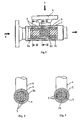
- a jacket tube 1 In a jacket tube 1, three packing bodies 2a, 2b and 2c are each offset by 90 ° from one another.
- passage openings 3 for the steam are arranged in each case in opposite regions between 2 adjacent layers of the packing body (cf. also FIGS. 2 and 3, a different embodiment for the arrangement of the openings being shown in FIG. 3).
- the steam 7 is introduced through a nozzle 4 and an annular space 5 through the openings 3 in fine jets into the packing body.
- the liquid 6 to be heated is introduced into the casing tube 1 in the axial direction (see arrow) and, after heating, likewise leaves it in the axial direction (see arrow).
- a control valve can be arranged in the steam feed line, which is controlled by the temperature of the product in such a way that the desired initial temperature is always reached.
- the invention also includes non-soluble systems, e.g. the warming up of liquid oil by direct condensation of water vapor.
- non-soluble systems e.g. the warming up of liquid oil by direct condensation of water vapor.
- a separator for the oil / water dispersion is arranged after the heat transfer.
Landscapes
- Engineering & Computer Science (AREA)
- Chemical & Material Sciences (AREA)
- Mechanical Engineering (AREA)
- General Engineering & Computer Science (AREA)
- Physics & Mathematics (AREA)
- Thermal Sciences (AREA)
- Organic Chemistry (AREA)
- Chemical Kinetics & Catalysis (AREA)
- Physical Or Chemical Processes And Apparatus (AREA)
- Heat-Exchange Devices With Radiators And Conduit Assemblies (AREA)
Claims (4)
Applications Claiming Priority (2)
| Application Number | Priority Date | Filing Date | Title |
|---|---|---|---|
| US06/849,002 US4919541A (en) | 1986-04-07 | 1986-04-07 | Gas-liquid mass transfer apparatus and method |
| US849002 | 1986-04-07 |
Publications (2)
| Publication Number | Publication Date |
|---|---|
| EP0240848A1 EP0240848A1 (fr) | 1987-10-14 |
| EP0240848B1 true EP0240848B1 (fr) | 1991-01-09 |
Family
ID=25304836
Family Applications (1)
| Application Number | Title | Priority Date | Filing Date |
|---|---|---|---|
| EP87104419A Expired - Lifetime EP0240848B1 (fr) | 1986-04-07 | 1987-03-25 | Dispositif pour l'échange de chaleur et/ou de masses |
Country Status (6)
| Country | Link |
|---|---|
| US (1) | US4919541A (fr) |
| EP (1) | EP0240848B1 (fr) |
| JP (1) | JPS62241531A (fr) |
| BR (1) | BR8701625A (fr) |
| DE (1) | DE3767195D1 (fr) |
| DK (1) | DK25187A (fr) |
Families Citing this family (20)
| Publication number | Priority date | Publication date | Assignee | Title |
|---|---|---|---|---|
| US5407274A (en) * | 1992-11-27 | 1995-04-18 | Texaco Inc. | Device to equalize steam quality in pipe networks |
| US5709468A (en) * | 1992-11-27 | 1998-01-20 | Texaco Group, Inc. | Method for equalizing steam quality in pipe networks |
| US6089549A (en) * | 1997-09-25 | 2000-07-18 | Koch-Glitsch, Inc. | Exchange column structured packing bed having packing bricks |
| US6334985B1 (en) * | 1998-08-18 | 2002-01-01 | Uop Llc | Static mixing reactor for uniform reactant temperatures and concentrations |
| DE19848780C1 (de) * | 1998-10-22 | 2000-05-25 | Krauss Maffei Kunststofftech | Homogenisier- und Temperierbehälter |
| DE10019414C2 (de) * | 2000-04-19 | 2003-06-12 | Ballard Power Systems | Vorrichtung zum Einleiten von Gas in einen Rohrabschnitt |
| EP1291078A3 (fr) * | 2001-09-10 | 2004-01-28 | Bayer Ag | Réacteur tubulair pour des nitrations adiabatiques |
| ATE353703T1 (de) * | 2001-10-16 | 2007-03-15 | Sulzer Chemtech Ag | Rohrstück mit einer einspeisestelle für ein additiv |
| ITPR20020001A1 (it) * | 2002-01-24 | 2003-07-25 | Sig Manzini Spa | Procedimento per sterilizzare prodotti alimentari, in particolare puree e/o concentrati. |
| US6767007B2 (en) | 2002-03-25 | 2004-07-27 | Homer C. Luman | Direct injection contact apparatus for severe services |
| US6857467B2 (en) * | 2003-02-07 | 2005-02-22 | Gestion Lach Inc. | Heat exchange system and method |
| WO2006107206A2 (fr) * | 2005-04-06 | 2006-10-12 | Stichting Voor De Technische Wetenschappen | Partie d'admission pour microreacteur |
| US20070126132A1 (en) * | 2005-12-07 | 2007-06-07 | Galgano Mark A | Vena contracta |
| GB0621388D0 (en) * | 2006-10-27 | 2006-12-06 | Rolls Royce Plc | A support matrix arrangement |
| CN101435664B (zh) * | 2007-11-12 | 2011-05-11 | 洛阳蓝海实业有限公司 | 大口径变声速增压热交换装置 |
| US8528503B2 (en) | 2009-02-27 | 2013-09-10 | Advanced Steam Technology | Heat exchange system and method |
| US9726443B2 (en) | 2009-02-27 | 2017-08-08 | Advanced Steam Technology | Heat exchange system and method |
| DK2685836T3 (da) * | 2011-03-17 | 2021-11-08 | Nestle Sa | Systemer og fremgangsmåder til varmeveksling |
| CN102162702B (zh) * | 2011-04-13 | 2013-06-26 | 长沙水泽加热设备制造有限公司 | 管线型混合式加热设备 |
| US9758736B2 (en) | 2015-02-27 | 2017-09-12 | General Electric Company | Steam injector for a gasification system |
Family Cites Families (13)
| Publication number | Priority date | Publication date | Assignee | Title |
|---|---|---|---|---|
| CA564178A (fr) * | 1958-10-07 | S. Slayter Rudolf | Dispositif pour melanger des fluides | |
| US3409274A (en) * | 1967-11-22 | 1968-11-05 | Combustion Eng | Mixing apparatus for high pressure fluids at different temperatures |
| CH537208A (de) * | 1971-04-29 | 1973-07-13 | Sulzer Ag | Mischeinrichtung für fliessfähige Medien |
| DE2414319C2 (de) * | 1974-03-25 | 1984-02-02 | Wiegand Karlsruhe Gmbh, 7505 Ettlingen | Vorrichtung zur Erhitzung einer Flüssigkeit durch Einführen von Dampf |
| DE2447369A1 (de) * | 1974-10-04 | 1976-04-22 | Basf Ag | Verfahren und vorrichtung zum einmischen von niedrigviskosen fluessigkeiten in hochviskose medien |
| US4046189A (en) * | 1975-08-04 | 1977-09-06 | Harsco Corporation | Water heater |
| DE2644378A1 (de) * | 1976-10-01 | 1978-04-06 | Fuellpack Dipl Brauerei Ing Di | Verfahren zur einleitung von gas, insbesondere kohlendioxidgas, in eine in einer leitung stroemende fluessigkeit, insbesondere ein getraenk, sowie einrichtung zur durchfuehrung des verfahrens |
| CH617357A5 (fr) * | 1977-05-12 | 1980-05-30 | Sulzer Ag | |
| DE2808854C2 (de) * | 1977-05-31 | 1986-05-28 | Gebrüder Sulzer AG, 8401 Winterthur | Mit Einbauten versehener Strömungskanal für ein an einem indirekten Austausch, insbesondere Wärmeaustausch, beteiligtes Medium |
| US4179222A (en) * | 1978-01-11 | 1979-12-18 | Systematix Controls, Inc. | Flow turbulence generating and mixing device |
| CH642564A5 (de) * | 1979-10-26 | 1984-04-30 | Sulzer Ag | Statische mischvorrichtung. |
| DE3043239C2 (de) * | 1980-11-15 | 1985-11-28 | Balcke-Dürr AG, 4030 Ratingen | Verfahren und Vorrichtung zum Vermischen mindestens zweier fluider Teilströme |
| FR2536520B1 (fr) * | 1982-11-24 | 1986-04-18 | Agronomique Inst Nat Rech | Procede et dispositif de traitement thermique de fluide comportant une condensation rapide de vapeur |
-
1986
- 1986-04-07 US US06/849,002 patent/US4919541A/en not_active Expired - Fee Related
-
1987
- 1987-01-16 DK DK025187A patent/DK25187A/da not_active Application Discontinuation
- 1987-03-09 JP JP62052247A patent/JPS62241531A/ja active Pending
- 1987-03-25 EP EP87104419A patent/EP0240848B1/fr not_active Expired - Lifetime
- 1987-03-25 DE DE8787104419T patent/DE3767195D1/de not_active Expired - Lifetime
- 1987-04-07 BR BR8701625A patent/BR8701625A/pt unknown
Also Published As
| Publication number | Publication date |
|---|---|
| JPS62241531A (ja) | 1987-10-22 |
| DE3767195D1 (de) | 1991-02-14 |
| BR8701625A (pt) | 1988-01-26 |
| US4919541A (en) | 1990-04-24 |
| DK25187D0 (da) | 1987-01-16 |
| EP0240848A1 (fr) | 1987-10-14 |
| DK25187A (da) | 1987-10-08 |
Similar Documents
| Publication | Publication Date | Title |
|---|---|---|
| EP0240848B1 (fr) | Dispositif pour l'échange de chaleur et/ou de masses | |
| EP0475284A1 (fr) | Procédé et dispositif pour agir sur des fluides au moyen d'une onde de choc de compression | |
| EP0290813B1 (fr) | Echangeur de chaleur, en particulier pour refroidir des gaz de crackage | |
| EP3518989B1 (fr) | Dispositif d'évaporation d'un milieu liquide dans une installation de mise en bouteille d'un produit de remplissage | |
| DE3411795A1 (de) | Verfahren zum betreiben von rohrbuendelwaermeaustauschern zum kuehlen von gasen | |
| DE1426648B2 (de) | Schnelldampferzeuger | |
| EP0123986A1 (fr) | Réchauffeur d'eau d'alimentation | |
| DE3607676C2 (fr) | ||
| DE3827828C2 (de) | Wärmeaustauscher | |
| DE2548540C3 (de) | Brennkammer für einen Flüssigkeitserhitzer | |
| EP0532852B1 (fr) | Echangeur de chaleur à évaporation | |
| DE19503506C2 (de) | Vorrichtung zur Nutzung von Wärme- und/oder Flüssigkeitsmengen aus Gas- und Flüssigkeitsströmen an Dampferzeugern | |
| DE1197909B (de) | Waermetauscher mit an lotrechten Wandrohren eines Heizgaszuges angeschlossenen Rohrbuendeln | |
| DE4219781C1 (fr) | ||
| DE532876C (de) | Waermeaustauschvorrichtung, insbesondere fuer Destillationsanlagen | |
| DE69914456T2 (de) | Apparat in einem infusionssystem fuer ein fluessiges lebensmittelprodukt | |
| DE3039065A1 (de) | Warmluft-heizvorrichtung | |
| DE2917498C2 (de) | Oberflächen-Wärmetauscher | |
| DE102009039397A1 (de) | Mikrostrukturverdampfer | |
| DE1961296C3 (de) | Dampferzeuger | |
| DE2724937C3 (de) | Brennerkopf für brennbare Stoffe enthaltende Abluft | |
| DE1100855B (de) | Vorrichtung zum Waermeaustausch zwischen einem Rauchgasstrom und einer zu erhitzenden Fluessigkeit | |
| DE2319869C3 (de) | Vorrichtung zur Speisewasservorwärmung | |
| DE19524216A1 (de) | Anlage für die Vorwärmung und Entgasung von Wasser | |
| DE2915486C2 (de) | Korrosionsbeständiger Mehrzug-Luftvorwärmer |
Legal Events
| Date | Code | Title | Description |
|---|---|---|---|
| PUAI | Public reference made under article 153(3) epc to a published international application that has entered the european phase |
Free format text: ORIGINAL CODE: 0009012 |
|
| AK | Designated contracting states |
Kind code of ref document: A1 Designated state(s): CH DE FR GB IT LI NL |
|
| 17P | Request for examination filed |
Effective date: 19880307 |
|
| 17Q | First examination report despatched |
Effective date: 19891006 |
|
| ITF | It: translation for a ep patent filed | ||
| GRAA | (expected) grant |
Free format text: ORIGINAL CODE: 0009210 |
|
| AK | Designated contracting states |
Kind code of ref document: B1 Designated state(s): CH DE FR GB IT LI NL |
|
| REF | Corresponds to: |
Ref document number: 3767195 Country of ref document: DE Date of ref document: 19910214 |
|
| ET | Fr: translation filed | ||
| GBT | Gb: translation of ep patent filed (gb section 77(6)(a)/1977) | ||
| PLBE | No opposition filed within time limit |
Free format text: ORIGINAL CODE: 0009261 |
|
| STAA | Information on the status of an ep patent application or granted ep patent |
Free format text: STATUS: NO OPPOSITION FILED WITHIN TIME LIMIT |
|
| 26N | No opposition filed | ||
| PGFP | Annual fee paid to national office [announced via postgrant information from national office to epo] |
Ref country code: DE Payment date: 19930213 Year of fee payment: 7 |
|
| PGFP | Annual fee paid to national office [announced via postgrant information from national office to epo] |
Ref country code: GB Payment date: 19930215 Year of fee payment: 7 |
|
| PGFP | Annual fee paid to national office [announced via postgrant information from national office to epo] |
Ref country code: FR Payment date: 19930219 Year of fee payment: 7 |
|
| PGFP | Annual fee paid to national office [announced via postgrant information from national office to epo] |
Ref country code: CH Payment date: 19930324 Year of fee payment: 7 |
|
| PG25 | Lapsed in a contracting state [announced via postgrant information from national office to epo] |
Ref country code: GB Effective date: 19940325 |
|
| PG25 | Lapsed in a contracting state [announced via postgrant information from national office to epo] |
Ref country code: LI Effective date: 19940331 Ref country code: CH Effective date: 19940331 |
|
| GBPC | Gb: european patent ceased through non-payment of renewal fee |
Effective date: 19940325 |
|
| PG25 | Lapsed in a contracting state [announced via postgrant information from national office to epo] |
Ref country code: FR Effective date: 19941130 |
|
| REG | Reference to a national code |
Ref country code: CH Ref legal event code: PL |
|
| PG25 | Lapsed in a contracting state [announced via postgrant information from national office to epo] |
Ref country code: DE Effective date: 19941201 |
|
| REG | Reference to a national code |
Ref country code: FR Ref legal event code: ST |
|
| PGFP | Annual fee paid to national office [announced via postgrant information from national office to epo] |
Ref country code: NL Payment date: 19950331 Year of fee payment: 9 |
|
| PG25 | Lapsed in a contracting state [announced via postgrant information from national office to epo] |
Ref country code: NL Effective date: 19961001 |
|
| NLV4 | Nl: lapsed or anulled due to non-payment of the annual fee |
Effective date: 19961001 |
|
| PG25 | Lapsed in a contracting state [announced via postgrant information from national office to epo] |
Ref country code: IT Free format text: LAPSE BECAUSE OF NON-PAYMENT OF DUE FEES;WARNING: LAPSES OF ITALIAN PATENTS WITH EFFECTIVE DATE BEFORE 2007 MAY HAVE OCCURRED AT ANY TIME BEFORE 2007. THE CORRECT EFFECTIVE DATE MAY BE DIFFERENT FROM THE ONE RECORDED. Effective date: 20050325 |