EP0240573A1 - Ultraschall-doppler-puls-gerät - Google Patents
Ultraschall-doppler-puls-gerät Download PDFInfo
- Publication number
- EP0240573A1 EP0240573A1 EP86905920A EP86905920A EP0240573A1 EP 0240573 A1 EP0240573 A1 EP 0240573A1 EP 86905920 A EP86905920 A EP 86905920A EP 86905920 A EP86905920 A EP 86905920A EP 0240573 A1 EP0240573 A1 EP 0240573A1
- Authority
- EP
- European Patent Office
- Prior art keywords
- signals
- range
- doppler
- pulse
- received
- Prior art date
- Legal status (The legal status is an assumption and is not a legal conclusion. Google has not performed a legal analysis and makes no representation as to the accuracy of the status listed.)
- Ceased
Links
Images


Classifications
-
- G—PHYSICS
- G01—MEASURING; TESTING
- G01S—RADIO DIRECTION-FINDING; RADIO NAVIGATION; DETERMINING DISTANCE OR VELOCITY BY USE OF RADIO WAVES; LOCATING OR PRESENCE-DETECTING BY USE OF THE REFLECTION OR RERADIATION OF RADIO WAVES; ANALOGOUS ARRANGEMENTS USING OTHER WAVES
- G01S15/00—Systems using the reflection or reradiation of acoustic waves, e.g. sonar systems
- G01S15/88—Sonar systems specially adapted for specific applications
- G01S15/89—Sonar systems specially adapted for specific applications for mapping or imaging
- G01S15/8906—Short-range imaging systems; Acoustic microscope systems using pulse-echo techniques
- G01S15/8979—Combined Doppler and pulse-echo imaging systems
Definitions
- the present invention relates to a pulse Doppler apparatus of a phased array system usable as medical ultrasonic equipment or a short-range sonar, and more particularly to an improvement in a method of forming a received ultrasonic beam.
- phased-array Doppler apparatus is normally provided in a form capable of being also used as and combined with a B-mode imaging device. Therefore, not only a probe but an initial-stage amplifier and a received-beam former (referred to also as “phase converter”) are commonly used for the purpose of both imaging and Doppler processings.
- Fig. 8 shows an example of an apparatus of this conventional type.
- an array probe 1 is driven by a pulse at a high voltage supplied by a transmitter/receiver circuit group 2, and transmits ultrasonic waves into a body organ.
- the transmitter/receiver circuit group includes high-voltage pulse generating circuits each corresponding to each element of the probe 1.
- the respective high-voltage pulse generating circuits are driven by a plurality of outputs from a transmitted-beam former 3.
- the transmitted-beam former 3 receives an output trigger pulse from a transmission trigger circuit 4, and outputs a plurality of output signals which are appropriately time-delayed, respectively.
- the transmission trigger circuit 4 is triggered by a signal obtained by dividing the frequency of a clock of a clock generator 6 by means of a frequency divider 5.
- the probe 1 converts echoes from body organs into electrical signals, and outputs them.
- the echo signals converted into electrical signals pass through the initial-stage amplifiers of the transmitter/receiver circuit group 2, and are input to a received-beam former 7.
- the received-beam former 7 after completion of phase matching, the echo signals are added and supplied as an output.
- This echo signal is supplied to a B-mode imaging echo filter 8 and a Doppler echo filter 9.
- the output from the echo filter 8 is passed through a logarithm compression RF amplifier 10, then detected by a detector 11 and supplied as a B-mode video signal.
- This video signal is input to a B-mode display device (not shown) on which a B-mode image display is produced.
- the output from the Doppler echo filter 9 is conducted into a coherent detector 12 in which only a Doppler signal relative to a transmitted spectrum is extracted in response to 90° out-of-phase reference waves supplied from a phase converter 13.
- the phase converter 13 uses as a carrier a clock of the clock generator 6 and outputs 90° out-of-phase reference waves.
- the echo signal is divided into two channels by the coherent detector 12, and the echo signals through the respective channels are gated by a range gate 14. Subsequently, only a signal in an effective frequency range is extracted in a Doppler filter 15, and is subjected to a Nyquist filter 16.
- the range gate 14 is a gate for selecting a Doppler signal from within a given sample volume belonging to an object depth, and a signal for controlling the gate is supplied by a range gate setter 17.
- the range gate setter 17 generates a range gate signal RG on the basis of an output from the transmission trigger circuit 4.
- a Doppler AF singal output from the Nyquist filter 16 is supplied to a frequency analyzer (not shown), and is analyzed therein. The result of the analysis is displayed on a display device (not shown) . Also, the Doppler AF signal can be directly monitored as an audio sound through a loudspeaker or the like.
- Echoes containing a Doppler shift from body organs are extremely weak as compared with echoes containing no Doppler shift.
- echoes from a blood stream is about 30dB lower than echoes from a surrounding body tissue.
- the echoes from the blood stream is commonly superimposed on those from the surrounding body tissue. Therefore, in order to . • positively pick'up the former echoes, the signal processing circuit employed requires a wide dynamic range and superior linearity.
- range gating is applied to the result obtained from phase matching and addition followed by coherent detection. Therefore, the control wave form of the gate and a gated result show a remarkably small duty ratio (1/30 to 1/300), and thus the dynamic range of the coherent detector becomes narrow accordingly. This gives rise to a problem in that the condition is unfavorable as compared with the case of CW Doppler signal processing in which the complete duration of a signal can be utilized (the duty ratio is 1.)
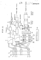
- an ultrasonic pulse Doppler apparatus including: range gate means (20) for separately performing range-gating of the respective received ultrasonic echo signals of the oscillation elements of an ultrasonic probe (1) each time the signals are respectively adjusted in correspondence with the direction of a received ultrasonic beam; pulse stretcher filter means (21) for extending the duration of the respective plurality of range-gated received signals while storing the energy of the signals; phasing/adding means (7a) for matching the phases of a plurality of output signals from the pulse stretcher filter means and performing addition thereof; detection means (12) for effecting coherent detection of an output signal from said phasing/adding means; and Doppler signal generating means (15, 16) for respectively generating Doppler signals on the basis of an output signal from the detection means.
- Fig. 1 is a diagram showing an embodiment of an ultrasonic pulse Doppler apparatus in accordance with the present invention.
- the embodiment differs from the prior-art apparatus shown in Fig. 8 in that a group of range gates are disposed forwards of a dedicated Doppler beam former and in that a group of stretcher filters are disposed rearwards of the range gates.
- a group of range gates indicated generally at 20 include n-number of range gates which are separately disposed in correspondence with the respective elements of the probe 1.
- the respective echo signals passing through the range gates 20 1 to 20 n are input to corresponding pulse stretcher filters 21 1 to 21 n .
- the respective outputs from the pulse stretcher filters 21 1 to 21 n are phase-matched and added by a dedicated-Doppler type received beam former 7a.
- the respective pulse stretcher filters 21 1 to 21 n are rounding-off filters (tuning circuits) for rounding off the envelopes of RF pulse signals.
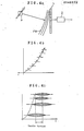
- the filters transform the wave form of the signal into that shown in Fig. 6(b) having a large duty ratio while storing the energy thereof.
- Such an filter may be constituted by a bandpass filter, for example, of any of LC, crystal, ceramic, and mechanical types. If the function of the pulse stretcher filter is considered from another viewpoint, as shown in Fig.
- the filter serves to extract one bright line spectrum from a group of bright line spectra which are periodically observed on frequency axes.
- the function of the stretcher is not necessarily limited only to an extraction action realized within an extremely narrow range indicated by slanting lines. Even a stretcher having a wide range as shown by a broken line performs a satisfactory function in a substantial sense.
- a system controller 22 is disposed so as to supply required control signals to the range gate group 20, the pulse stretcher filter group 21, the received beam former 7a and the like.
- the moment of range-gating a signal received by each of the elements of the probe 1 is controlled by a system controller 22 so that the received signals are distributed along the time axis as shown in Fig. 4b in accordance with the manner of incidence of an object wave front FW propagating from an object point P, for example, as shown in Fig. 4a.
- Fig. 4b time elapses from right to left along the time axis.
- the received signals of the respective elements of the probe 1 which have been range-gated are passed through the corresponding ⁇ pulse stretcher filters 21.
- the respective durations of the outputs from the pulse stretcher filters 21 are extended as shown in Fig..4c.
- phase difference between the respective signals in the usable section is in a range of + 180°. Therefore, phase adjustment for phase-matching and adding these signals can be performed in a range of + 180° irrespective of the timing of the range gate.
- This phase matching is performed by the received beam former 7a, and the signals are phase-matched and added and are output from the beam former 7a.
- the output is detected by the coherent detector 12.
- the coherent detector 12 may be constituted, for example, by two pairs of balanced demodulators (BDM).
- the range gate is disposed for the channel of each of the elements of the probe, and their opening and closing time is individually controlled. Therefore, the respective signal levels to be processed by the range gates are matched in phase and added, thereby being adjusted in such a manner that the amplitude is not increased. Accordingly, the risk of the received signals reaching the limit of the dynamic range of the signal processing circuit is further reduced as compared with the prior art. Also, after the received-beam signals from the respective elements have been subjected to range-gating, they are passed through narrow-band filters serving as a pulse stretcher. Therefore, the output from the pulse stretcher filters show a large duty ratio (that is, the peak factor is small), and thus can be handled by the coherent detector. The dynamic range of the coherent detector becomes equal to the case of handling CW Doppler signals.
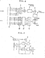
- Fig. 5 is a block diagram of the construction of the essential portion of another embodiment of the present invention. Specifically, the respective outputs from the pulse stretcher filters 21 1 to 21 n are subjected to coherent detection by the balanced demodulator BDM, and the respective groups of signals i and q are separately phase-matched and added. The phase matching is performed by adjusting the phase of a reference carrier at the time of coherent • detection.
- a phase map 30 is disposed so as to generate a group of demodulating carriers, and, for example, a digital circuit made up of shift registers may be used for the phase map 30.
- F ig. 6 is a block diagram of the construction of the essential portion of still another embodiment of the present invention.
- the system of the present invention contemplates shaping a pulse Doppler received signal into a CW Doppler form or similar.
- the present invention is well suited for a CW Doppler arrangement irrespective of whether or not the same array is used or another dedicated two-element probe is used, .
- the arrangement of the invention can be easily changed to a CW Doppler arrangement.
- Fig. 6 shows this manner. In this case, although the function of the pulse stretcher filter 21 is not effectively utilized, it may be interposed in the circuit.
- the CW signal from its reception element may be supplied forwards or rearwards of the pulse. stretcher filter.
Landscapes
- Physics & Mathematics (AREA)
- Engineering & Computer Science (AREA)
- Radar, Positioning & Navigation (AREA)
- Remote Sensing (AREA)
- Acoustics & Sound (AREA)
- Computer Networks & Wireless Communication (AREA)
- General Physics & Mathematics (AREA)
- Ultra Sonic Daignosis Equipment (AREA)
Applications Claiming Priority (2)
| Application Number | Priority Date | Filing Date | Title |
|---|---|---|---|
| JP213789/85 | 1985-09-27 | ||
| JP60213789A JPS6274342A (ja) | 1985-09-27 | 1985-09-27 | 超音波パルスドプラ装置 |
Publications (2)
| Publication Number | Publication Date |
|---|---|
| EP0240573A1 true EP0240573A1 (de) | 1987-10-14 |
| EP0240573A4 EP0240573A4 (de) | 1988-01-21 |
Family
ID=16645077
Family Applications (1)
| Application Number | Title | Priority Date | Filing Date |
|---|---|---|---|
| EP19860905920 Ceased EP0240573A4 (de) | 1985-09-27 | 1986-09-26 | Ultraschall-doppler-puls-gerät. |
Country Status (4)
| Country | Link |
|---|---|
| US (1) | US4759373A (de) |
| EP (1) | EP0240573A4 (de) |
| JP (1) | JPS6274342A (de) |
| WO (1) | WO1987001925A1 (de) |
Cited By (1)
| Publication number | Priority date | Publication date | Assignee | Title |
|---|---|---|---|---|
| CN110680349A (zh) * | 2019-10-29 | 2020-01-14 | 华南理工大学 | 一种基于线性调频的脉搏测谎方法与装置 |
Families Citing this family (7)
| Publication number | Priority date | Publication date | Assignee | Title |
|---|---|---|---|---|
| US5555534A (en) * | 1994-08-05 | 1996-09-10 | Acuson Corporation | Method and apparatus for doppler receive beamformer system |
| US6558329B1 (en) * | 2000-04-28 | 2003-05-06 | Koninklijke Philips Electronics N.V. | Medical ultrasound receive architecture |
| WO2008008936A2 (en) * | 2006-07-13 | 2008-01-17 | The Regents Of The University Of Colorado | Echo particle image velocity (epiv) and echo particle tracking velocimetry (eptv) system and method |
| US7808423B2 (en) * | 2007-04-05 | 2010-10-05 | Honeywell International Inc. | Methods for rapid target acquisitions in range measurement systems |
| US20090099453A1 (en) * | 2007-10-16 | 2009-04-16 | Kjell Kristoffersen | Stand-alone cw doppler probe interface for phased array ultrasound system |
| WO2009141690A1 (en) * | 2008-05-23 | 2009-11-26 | Oscillon Ltd | Method and device for recognizing tissue structure using doppler effect |
| CN102613990B (zh) * | 2012-02-03 | 2014-07-16 | 声泰特(成都)科技有限公司 | 三维超声频谱多普勒的血流速度及其空间分布显示方法 |
Family Cites Families (7)
| Publication number | Priority date | Publication date | Assignee | Title |
|---|---|---|---|---|
| GB1492987A (en) * | 1974-07-02 | 1977-11-23 | Secr Defence | Surface acoustic wave devices |
| US4182173A (en) * | 1978-08-23 | 1980-01-08 | General Electric Company | Duplex ultrasonic imaging system with repetitive excitation of common transducer in doppler modality |
| JPS6118464Y2 (de) * | 1979-04-23 | 1986-06-04 | ||
| JPS5897347A (ja) * | 1981-12-03 | 1983-06-09 | 株式会社東芝 | 超音波診断装置 |
| US4598589A (en) * | 1984-07-17 | 1986-07-08 | General Electric Company | Method of CW doppler imaging using variably focused ultrasonic transducer array |
| US4640292A (en) * | 1984-08-28 | 1987-02-03 | Hewlett-Packard Company | Extending sample volume in pulsed Doppler systems |
| US4598716A (en) * | 1984-12-03 | 1986-07-08 | Hileman Ronald E | Doppler method and apparatus for measuring fluid motion |
-
1985
- 1985-09-27 JP JP60213789A patent/JPS6274342A/ja active Granted
-
1986
- 1986-09-26 EP EP19860905920 patent/EP0240573A4/de not_active Ceased
- 1986-09-26 US US07/057,969 patent/US4759373A/en not_active Expired - Fee Related
- 1986-09-26 WO PCT/JP1986/000495 patent/WO1987001925A1/ja not_active Ceased
Cited By (2)
| Publication number | Priority date | Publication date | Assignee | Title |
|---|---|---|---|---|
| CN110680349A (zh) * | 2019-10-29 | 2020-01-14 | 华南理工大学 | 一种基于线性调频的脉搏测谎方法与装置 |
| CN110680349B (zh) * | 2019-10-29 | 2021-07-20 | 华南理工大学 | 一种基于线性调频的脉搏测谎方法与装置 |
Also Published As
| Publication number | Publication date |
|---|---|
| JPS6274342A (ja) | 1987-04-06 |
| US4759373A (en) | 1988-07-26 |
| EP0240573A4 (de) | 1988-01-21 |
| WO1987001925A1 (fr) | 1987-04-09 |
| JPH0228973B2 (de) | 1990-06-27 |
Similar Documents
| Publication | Publication Date | Title |
|---|---|---|
| EP0014793B1 (de) | Ultraschall-System und-Verfahren für Richtungsbestimmung von Blutgeschwindigkeiten | |
| KR100532359B1 (ko) | 휴대형초음파진단기용초음파어레이트랜스듀서트랜시버 | |
| US4265126A (en) | Measurement of true blood velocity by an ultrasound system | |
| US4702258A (en) | Device for combined B-scan and B/A imaging | |
| US5188112A (en) | Ultrasonic Doppler imaging systems with improved flow sensitivity | |
| JPS60122548A (ja) | 超音波診断装置 | |
| US4759373A (en) | Ultrasonic pulse doppler apparatus | |
| EP0248623B1 (de) | Ultraschall Abtastgerät | |
| US6645146B1 (en) | Method and apparatus for harmonic imaging using multiple transmissions | |
| US6485424B2 (en) | Image forming method and apparatus, and ultrasonic imaging apparatus | |
| US5050611A (en) | Ultrasonic imaging apparatus | |
| US6047601A (en) | Self-tuning crystal notch filter | |
| US5081996A (en) | Ultrasonic imaging apparatus | |
| US5018528A (en) | Pulse Doppler ultrasonic diagnostic system | |
| JP2916219B2 (ja) | 超音波診断装置 | |
| JPS61146242A (ja) | 超音波診断装置 | |
| US5331963A (en) | Apparatus for examining objects by ultrasonic echography | |
| JPH02164346A (ja) | 超音波パルスドプラ血流診断装置 | |
| JPH0228974B2 (ja) | Iyochoonpaparusudopurasochi | |
| JPH02236480A (ja) | レーダ装置 | |
| JPH0720468B2 (ja) | 血流データ処理方法 | |
| JPS6398580A (ja) | レ−ダ装置 | |
| JPS62137041A (ja) | 超音波診断装置 | |
| JPS6113945A (ja) | 超音波診断装置 | |
| JPS61232837A (ja) | 超音波診断装置 |
Legal Events
| Date | Code | Title | Description |
|---|---|---|---|
| PUAI | Public reference made under article 153(3) epc to a published international application that has entered the european phase |
Free format text: ORIGINAL CODE: 0009012 |
|
| AK | Designated contracting states |
Kind code of ref document: A1 Designated state(s): DE GB |
|
| 17P | Request for examination filed |
Effective date: 19871001 |
|
| A4 | Supplementary search report drawn up and despatched |
Effective date: 19880121 |
|
| 17Q | First examination report despatched |
Effective date: 19910222 |
|
| STAA | Information on the status of an ep patent application or granted ep patent |
Free format text: STATUS: THE APPLICATION HAS BEEN REFUSED |
|
| 18R | Application refused |
Effective date: 19920423 |
|
| RIN1 | Information on inventor provided before grant (corrected) |
Inventor name: TAKEUCHI, YASUHITOYOKOGAWA MEDICAL SYSTEMS, LTD. |