EP0240482A2 - Vorrichtung zum Giessen von Stahl - Google Patents
Vorrichtung zum Giessen von Stahl Download PDFInfo
- Publication number
- EP0240482A2 EP0240482A2 EP87870041A EP87870041A EP0240482A2 EP 0240482 A2 EP0240482 A2 EP 0240482A2 EP 87870041 A EP87870041 A EP 87870041A EP 87870041 A EP87870041 A EP 87870041A EP 0240482 A2 EP0240482 A2 EP 0240482A2
- Authority
- EP
- European Patent Office
- Prior art keywords
- section
- channel
- steel
- nozzle
- final
- Prior art date
- Legal status (The legal status is an assumption and is not a legal conclusion. Google has not performed a legal analysis and makes no representation as to the accuracy of the status listed.)
- Granted
Links
- 229910000831 Steel Inorganic materials 0.000 title claims abstract description 77
- 239000010959 steel Substances 0.000 title claims abstract description 77
- 238000005266 casting Methods 0.000 title claims abstract description 17
- 238000009434 installation Methods 0.000 title 1
- 238000001816 cooling Methods 0.000 claims abstract description 21
- 239000007788 liquid Substances 0.000 claims abstract description 19
- 238000003756 stirring Methods 0.000 claims abstract description 8
- 238000013019 agitation Methods 0.000 claims abstract description 7
- 239000004020 conductor Substances 0.000 claims description 19
- 230000005672 electromagnetic field Effects 0.000 claims description 7
- 239000000463 material Substances 0.000 claims description 7
- 230000005611 electricity Effects 0.000 claims description 4
- 239000011261 inert gas Substances 0.000 claims description 4
- 239000002826 coolant Substances 0.000 claims description 2
- 238000000034 method Methods 0.000 description 6
- 230000002093 peripheral effect Effects 0.000 description 6
- 238000007711 solidification Methods 0.000 description 6
- 230000008023 solidification Effects 0.000 description 6
- 210000003462 vein Anatomy 0.000 description 5
- 229910052582 BN Inorganic materials 0.000 description 4
- PZNSFCLAULLKQX-UHFFFAOYSA-N Boron nitride Chemical compound N#B PZNSFCLAULLKQX-UHFFFAOYSA-N 0.000 description 4
- 235000011837 pasties Nutrition 0.000 description 4
- 229910052581 Si3N4 Inorganic materials 0.000 description 3
- 230000009471 action Effects 0.000 description 3
- 238000009749 continuous casting Methods 0.000 description 3
- 230000000694 effects Effects 0.000 description 3
- 239000007789 gas Substances 0.000 description 3
- 230000006698 induction Effects 0.000 description 3
- 238000013021 overheating Methods 0.000 description 3
- HQVNEWCFYHHQES-UHFFFAOYSA-N silicon nitride Chemical compound N12[Si]34N5[Si]62N3[Si]51N64 HQVNEWCFYHHQES-UHFFFAOYSA-N 0.000 description 3
- XLYOFNOQVPJJNP-UHFFFAOYSA-N water Substances O XLYOFNOQVPJJNP-UHFFFAOYSA-N 0.000 description 3
- RYGMFSIKBFXOCR-UHFFFAOYSA-N Copper Chemical compound [Cu] RYGMFSIKBFXOCR-UHFFFAOYSA-N 0.000 description 2
- 229920000297 Rayon Polymers 0.000 description 2
- 239000000919 ceramic Substances 0.000 description 2
- 229910052802 copper Inorganic materials 0.000 description 2
- 239000010949 copper Substances 0.000 description 2
- 238000010586 diagram Methods 0.000 description 2
- RVTZCBVAJQQJTK-UHFFFAOYSA-N oxygen(2-);zirconium(4+) Chemical compound [O-2].[O-2].[Zr+4] RVTZCBVAJQQJTK-UHFFFAOYSA-N 0.000 description 2
- 239000002245 particle Substances 0.000 description 2
- 239000002964 rayon Substances 0.000 description 2
- 239000011819 refractory material Substances 0.000 description 2
- 238000010008 shearing Methods 0.000 description 2
- HBMJWWWQQXIZIP-UHFFFAOYSA-N silicon carbide Chemical compound [Si+]#[C-] HBMJWWWQQXIZIP-UHFFFAOYSA-N 0.000 description 2
- 229910010271 silicon carbide Inorganic materials 0.000 description 2
- 229910001928 zirconium oxide Inorganic materials 0.000 description 2
- 208000031968 Cadaver Diseases 0.000 description 1
- OKTJSMMVPCPJKN-UHFFFAOYSA-N Carbon Chemical compound [C] OKTJSMMVPCPJKN-UHFFFAOYSA-N 0.000 description 1
- 230000001944 accentuation Effects 0.000 description 1
- 230000004323 axial length Effects 0.000 description 1
- 230000015572 biosynthetic process Effects 0.000 description 1
- 229910052799 carbon Inorganic materials 0.000 description 1
- 239000000470 constituent Substances 0.000 description 1
- 230000003247 decreasing effect Effects 0.000 description 1
- 230000005684 electric field Effects 0.000 description 1
- 238000010292 electrical insulation Methods 0.000 description 1
- 230000003628 erosive effect Effects 0.000 description 1
- 230000004907 flux Effects 0.000 description 1
- 239000012634 fragment Substances 0.000 description 1
- 230000006872 improvement Effects 0.000 description 1
- 239000000203 mixture Substances 0.000 description 1
- 230000035515 penetration Effects 0.000 description 1
- 230000008569 process Effects 0.000 description 1
- 239000007787 solid Substances 0.000 description 1
- 239000000725 suspension Substances 0.000 description 1
Images

Classifications
-
- B—PERFORMING OPERATIONS; TRANSPORTING
- B22—CASTING; POWDER METALLURGY
- B22D—CASTING OF METALS; CASTING OF OTHER SUBSTANCES BY THE SAME PROCESSES OR DEVICES
- B22D41/00—Casting melt-holding vessels, e.g. ladles, tundishes, cups or the like
- B22D41/50—Pouring-nozzles
- B22D41/58—Pouring-nozzles with gas injecting means
-
- B—PERFORMING OPERATIONS; TRANSPORTING
- B22—CASTING; POWDER METALLURGY
- B22D—CASTING OF METALS; CASTING OF OTHER SUBSTANCES BY THE SAME PROCESSES OR DEVICES
- B22D41/00—Casting melt-holding vessels, e.g. ladles, tundishes, cups or the like
- B22D41/50—Pouring-nozzles
- B22D41/62—Pouring-nozzles with stirring or vibrating means
Definitions
- the present invention relates to a device for casting, in particular for the continuous casting of steel.
- the liquid steel intended for casting is contained in a container such as a steel ladle or a distribution basket from which it is poured into the ingot mold through an orifice generally located in the bottom of the container.
- This orifice is normally provided with a closure device making it possible to modify the steel flow rate and possibly to interrupt the casting.
- the pouring orifice is constituted by a generally shaped part. tubular, called a nozzle; this tubular part, as well as the closure device which is associated with it, are generally made of a refractory material, in order to avoid any cooling of the steel which comes into contact with them.
- the present invention provides a process for carrying out this pasty phase during the casting of steel.
- the method of the present invention in which the steel is poured through a nozzle, is essentially characterized in that one causes a partial solidification of the peripheral layers of the steel in contact with the walls of the nozzle, and in that one creates within the steel in the nozzle sufficient agitation to suspend in the liquid steel steel particles from the peripheral layers being solidified.
- the steel has a low overheating, that is to say less than 30 ° C, before entering the nozzle.
- said partial solidification is caused by carrying out intense cooling of the walls of the nozzle.
- agitation is created in the steel by means of a rotating electromagnetic field.
- Such an electromagnetic field can be established by means of coils judiciously arranged around the steel vein.
- the rotating electromagnetic field induces forces in the steel which create agitation and lead to the appearance of shear stresses, which give rise to high deformation rates in particular in the zone in the course of solidification.
- This rotational movement of the steel in the nozzle can be further accentuated, in accordance with the invention, if an inert gas is injected into the steel in the vicinity of the entry of the steel into the nozzle. There is thus formed, at the inlet of the nozzle, a gas pocket which causes the formation of a vortex within the liquid steel.
- this gas pocket extends into the nozzle itself.
- the steel flowing through the nozzle is thus applied against the interior, cooled wall of the pouring channel, which promotes the cooling of its peripheral layers.
- peripheral cooling and shearing thus causes the appearance of a pasty phase which retains good fluidity and which therefore does not disturb the flow of steel through the nozzle.
- the proportion of the solid fraction which is thus suspended in the liquid steel can be adjusted, by varying the intensity of the cooling and the viscosity of the mixture by modifying at least one of the parameters of the rotating field. , for example its frequency or intensity, and / or the flow rate of said inert gas.
- the direction of rotation of the vortex caused by said inert gas is preferably the same as the direction of rotation imparted by the rotating field.
- Another object of the present invention is to provide a pouring nozzle which, thanks to its particular configuration and constitution, makes it possible to create conditions which lead to the appearance of a pasty phase in the steel, during its path between the ladle or the tundish on the one hand and the ingot mold on the other.
- the pouring device of the nozzle type, which is the subject of the present invention is characterized in that it comprises a body in which is formed a liquid steel pouring channel, first means of cooling to ensure the cooling of said body as well as second stirring means to create agitation within the liquid steel located in said channel.
- the inlet and outlet sections of said channel are of different dimensions, said outlet section being capable of ensuring the targeted steel flow taking into account the height of the charge of liquid steel at - above this section.
- said channel may comprise at least two sections of different passage sections and, over at least part of its length, have a passage section greater than said outlet section.
- said channel has a final section of short length, the section of which is constant and equal to said outlet section, an initial section of which the section is constant and greater than said outlet section, and an intermediate section connecting the initial section and the final section and the section of which varies continuously from the section of the initial section to the section of the final section.
- the element in which said channel is formed advantageously consists of two parts, one part, said body of the nozzle having the initial section of said channel, and the other part, said head of the nozzle, presenting the intermediate section and the final section of said channel.
- the inner surface of the nozzle carries inclined ribs, of short length, preferably arranged in the vicinity of the entrance to said channel.
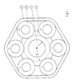
- FIG. 1 there is shown in 1 the channel of radius r through which the steel stream flows through the nozzle 2.
- the reference numeral 3 denotes the conductors grouped in pairs (1 +, 1 -; 2 +, 2 -; 3 +, 3-) to constitute three inductors connected to the three phases of a three-phase current source not shown. The whole is joined by an envelope 4.
- the steel vein flows through channel 1 perpendicular to the plane of the drawing, in the direction indicated by the arrow in the center.
- the nozzle 2 is made of a material which is both a good conductor of heat, to facilitate the cooling of the steel, and electrically insulating, so as not to disturb the electromagnetic field.
- a material based on boron nitride, silicon nitride or silicon carbide for example use a material based on boron nitride, silicon nitride or silicon carbide.
- the conductors 3 consist of tubes made of a material which is a good conductor of heat and electricity, for example copper. They penetrate the thickness of the wall of the nozzle and they are traversed by water; they provide both intense cooling of the nozzle 2 and the application of the electromagnetic field.
- the outer casing 4 is preferably made of a material which does not conduct electricity.
- a cooling agent preferably gaseous, can be circulated in the channels between the outer casing 4, the conductors 3 and the nozzle 2.
- a boron nitride nozzle having an internal radius r of 10 mm was used, while the radius R of the circumference tangent to the conductors 3 was equal to 15 mm.
- the intensity of the induction at the level of the inductors was 20 mT and the current density at the periphery of the steel vein amounted to 12.5. 106 A / m2.
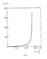
- This same figure 2 also shows (ordinates - right axis) the evolution of the speed of deformation V d in steel along the radius r. This rate of deformation increases first very slightly from the center, then very suddenly in the zone being solidified. This growth in the rate of deformation causes the solidified layer to disintegrate as it is formed.
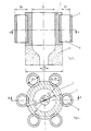
- FIGS. 1 and 3 the nozzles are shown in their normal casting position, that is to say with the liquid steel flowing from top to bottom, and in FIGS. 1, 3 and 4, the same constituents are designated by the same reference numerals.
- the nozzle shown schematically in Figure 3 consists of a nozzle body 2 and a nozzle head 5 which succeed one another without interruption in the direction of flow of the liquid steel. These two parts are fixed to each other by means not shown.
- an initial section of diameter D1 of the pouring channel In the body of the nozzle 2 is formed an initial section of diameter D1, of the pouring channel, while the head of the nozzle 5 is provided with the final section, of diameter D6, and of the intermediate section, with a decreasing diameter of D1 to D6, of said sprue.
- Tubular electrical conductors 3 are distributed over the periphery of the nozzle body 2; they are cooled by a circulation of water 6. These conductors 3 are further connected to an alternating current source, not shown.
- the outer casing 4 ( Figure 1) is not shown here. These conductors 3 are intended on the one hand to inductively stir the steel present in the initial section of the pouring channel and on the other hand to cause, by cooling, a beginning of solidification of this steel, in particular in the close areas of the wall of the sprue.
- the pouring channel has in its initial section a diameter D1 greater than the diameter D6 of the outlet section, the latter being determined so as to ensure the desired steel flow, taking into account the height of the load of liquid steel above the outlet section.
- the nozzle conforms to the invention allows an accentuation on the one hand of the solidification of the steel under the action of the cooled conductors 3 and on the other hand of the rotational movement of the steel caused by the rotating electric field applied by the conductors 3.
- FIG. 4 shows the peripheral distribution of the conductors 3 around the nozzle body 2, as well as their penetration into the thickness of this nozzle body 2.
- the nozzle body 2 and the nozzle head 5 are advantageously made of different refractory materials adapted to the respective functions of these two parts.
- the nozzle body is made of a material which is a good conductor of heat and a poor conductor of electricity, in order to ensure both the cooling of the steel and the electrical insulation of the conductors 3.
- a material which is a good conductor of heat and a poor conductor of electricity in order to ensure both the cooling of the steel and the electrical insulation of the conductors 3.
- a material having a high resistance to erosion in particular zirconium oxide.
- the outlet section of the nozzle head 5, or its diameter is determined so as to ensure the flow of steel, that is to say say the desired casting speed (in t / h for example), taking into account the height of the liquid steel charge above this section.
- An assimilation between the section and the diameter of the pouring channel is justified by the fact that this channel usually has a circular section.
- the diameter of the initial section of the pouring channel, ie D1 should advantageously be between two and five times the diameter of the outlet section D6.
- the final section of the pouring channel will have an axial length of between once and three times the diameter of the outlet section D6.
- a length at least equal to the diameter is necessary to cancel the tangential component of the speed of flow of the steel. Beyond three times this diameter, an increase in this length does not bring any more improvement in this respect, it only results in an unnecessary increase in the price of the nozzle head.
- a nozzle was produced in accordance with the invention, the body of which was made of a ceramic composed of boron nitride and silicon nitride, and the head of which was made of zirconium oxide.
- the conductors 3 were copper tubes traversed by water circulating at high speed.
- the steel had a carbon content of 0.7% and it showed 25 ° C overheating at the inlet of the nozzle.
- the steel flow rate to be insured amounted to 20 t / h.
- the three-phase inductor with a pair of poles was supplied with current having a frequency of 3000 Hz and an intensity per phase of 1550 A.
- the magnetic induction at the level of the inductor was 20 mT.
- the steel had an axial speed of 0.25 m / s and a tangential speed of 1.5 m / s.
- the result was the possibility of removing a heat flux of 0.56 kW / m.
- This speed increases rapidly and sharply in the vicinity of the cooled wall of the channel, that is to say in the zone where the cooling of the steel is most pronounced. It reflects the disintegration of the solidified steel layer, which thus retains sufficient fluidity for casting.
Landscapes
- Engineering & Computer Science (AREA)
- Mechanical Engineering (AREA)
- Continuous Casting (AREA)
Priority Applications (1)
| Application Number | Priority Date | Filing Date | Title |
|---|---|---|---|
| AT87870041T ATE56643T1 (de) | 1986-04-02 | 1987-04-01 | Vorrichtung zum giessen von stahl. |
Applications Claiming Priority (6)
| Application Number | Priority Date | Filing Date | Title |
|---|---|---|---|
| BE6048215 | 1986-04-02 | ||
| BE6/48215A BE904545A (fr) | 1986-04-02 | 1986-04-02 | Procede pour la coulee de l'acier. |
| BE6048253 | 1986-08-08 | ||
| BE6/48253A BE905256A (fr) | 1986-08-08 | 1986-08-08 | Dispositif pour la coulee de l'acier. |
| BE6048278 | 1986-12-17 | ||
| BE6/48278A BE905968R (fr) | 1986-04-02 | 1986-12-17 | Procede et dispositif pour la coulee de l'acier. |
Publications (3)
| Publication Number | Publication Date |
|---|---|
| EP0240482A2 true EP0240482A2 (de) | 1987-10-07 |
| EP0240482A3 EP0240482A3 (en) | 1988-01-13 |
| EP0240482B1 EP0240482B1 (de) | 1990-09-19 |
Family
ID=27159695
Family Applications (1)
| Application Number | Title | Priority Date | Filing Date |
|---|---|---|---|
| EP19870870041 Expired - Lifetime EP0240482B1 (de) | 1986-04-02 | 1987-04-01 | Vorrichtung zum Giessen von Stahl |
Country Status (1)
| Country | Link |
|---|---|
| EP (1) | EP0240482B1 (de) |
Family Cites Families (4)
| Publication number | Priority date | Publication date | Assignee | Title |
|---|---|---|---|---|
| GB705762A (en) * | 1951-10-15 | 1954-03-17 | Skf Svenska Kullagerfab Ab | Improvements relating to the continuous casting of metals |
| BE893168A (fr) * | 1982-05-13 | 1982-11-16 | Vesuvius Internat Corp | Orifice d'injection d'un gaz de protection dans un tube de coulee |
| LU84617A1 (fr) * | 1983-01-31 | 1984-10-24 | Arbed | Busettes pour lingotieres ainsi que leur utilisation |
| BE903805A (fr) * | 1985-12-05 | 1986-06-05 | Centre Rech Metallurgique | Procede pour la coulee continue des metaux. |
-
1987
- 1987-04-01 EP EP19870870041 patent/EP0240482B1/de not_active Expired - Lifetime
Also Published As
| Publication number | Publication date |
|---|---|
| EP0240482B1 (de) | 1990-09-19 |
| EP0240482A3 (en) | 1988-01-13 |
Similar Documents
| Publication | Publication Date | Title |
|---|---|---|
| EP0275228B1 (de) | Verfahren und Anlage zum Schmelzen und Stranggiessen von Metallen | |
| CA2128936C (fr) | Procede de fusion d'un materiau electroconducteur dans un four de fusion par induction en creuset froid et four de fusion pour la mise en oeuvre de ce procede | |
| EP0269180B1 (de) | Vorrichtung zum Giessen eines pastenartigen Metalles | |
| FR2688516A1 (fr) | Dispositif pour la fabrication de metaux et d'alliages de metaux de grande purete. | |
| FR3005154A1 (fr) | Four a chauffage par induction electromagnetique, utilisation du four pour la fusion d'un melange de metal(ux) et d'oxyde(s) representatif d'un corium | |
| EP0005676A2 (de) | Elektromagnetisches Rührverfahren beim Stranggiessen | |
| FR2575683A1 (fr) | Procede et installation pour la fabrication continue de tuyaux en fonte a graphite spheroidal a structure controlee | |
| FR2480154A1 (fr) | Procede et appareil de coulee electromagnetique de bandes minces | |
| LU85846A1 (fr) | Dispositif de brassage de metal en fusion dans une installation de coulee continue | |
| FR2521463A1 (fr) | Procede de coulee continue ou semi-continue de produits metalliques legers | |
| EP0240482B1 (de) | Vorrichtung zum Giessen von Stahl | |
| FR2571484A1 (fr) | Procede et dispositif pour faire fondre progressivement du materiau en forme de barreau au moyen d'une bobine d'induction | |
| FR2646859A1 (fr) | Procede et appareil pour regler les isothermes d'electrode dans une refonte d'electro-laitier | |
| FR2555080A1 (fr) | Procede et appareil pour eviter la formation d'un tourbillon dans un recipient metallurgique de coulee a sortie par le fond | |
| EP0242347A2 (de) | Vorrichtung zum Giessen einer flüssig-festen Mischung | |
| EP0586481B1 (de) | Verfahren und vorrichtung zur herstellung von amorphem metalldraht auf eisenbasis | |
| EP0038275B1 (de) | Vorrichtung zum Stranggiessen von Rohrluppen | |
| BE905256A (fr) | Dispositif pour la coulee de l'acier. | |
| BE904545A (fr) | Procede pour la coulee de l'acier. | |
| FR2628993A3 (fr) | Dispositif d'obturation laterale de l'espace de coulee d'une lingotiere de coulee continue entre cylindres | |
| EP0290423B1 (de) | Vorrichtung zur kontinuierlichen Herstellung eines dünnen Metallbands | |
| FR2695846A1 (fr) | Paroi d'obturation latérale d'une installation de coulée continue des métaux entre parois mobiles et installation comportant une telle paroi. | |
| BE1000221A6 (fr) | Dispositif pour la coulee d'un metal en phase pateuse. | |
| EP1152855B1 (de) | Verfahren und vorrichtung zum giessen von werkstücken aus titan | |
| FR2553317A1 (fr) | Joint pour installation de coulee continue horizontale des metaux notamment de l'acier et installation de coulee equipee de ce joint |
Legal Events
| Date | Code | Title | Description |
|---|---|---|---|
| PUAI | Public reference made under article 153(3) epc to a published international application that has entered the european phase |
Free format text: ORIGINAL CODE: 0009012 |
|
| AK | Designated contracting states |
Kind code of ref document: A2 Designated state(s): AT DE ES FR GB IT LU NL SE |
|
| PUAL | Search report despatched |
Free format text: ORIGINAL CODE: 0009013 |
|
| AK | Designated contracting states |
Kind code of ref document: A3 Designated state(s): AT DE ES FR GB IT LU NL SE |
|
| 17P | Request for examination filed |
Effective date: 19880707 |
|
| 17Q | First examination report despatched |
Effective date: 19890301 |
|
| GRAA | (expected) grant |
Free format text: ORIGINAL CODE: 0009210 |
|
| AK | Designated contracting states |
Kind code of ref document: B1 Designated state(s): AT DE ES FR GB IT LU NL SE |
|
| PG25 | Lapsed in a contracting state [announced via postgrant information from national office to epo] |
Ref country code: IT Free format text: LAPSE BECAUSE OF FAILURE TO SUBMIT A TRANSLATION OF THE DESCRIPTION OR TO PAY THE FEE WITHIN THE PRE;WARNING: LAPSES OF ITALIAN PATENTS WITH EFFECTIVE DATE BEFORE 2007 MAY HAVE OCCURRED AT ANY TIME BEFORE 2007. THE CORRECT EFFECTIVE DATE MAY BE DIFFERENT FROM THE ONE RECORDED.SCRIBED TIME-LIMIT Effective date: 19900919 Ref country code: SE Effective date: 19900919 Ref country code: NL Effective date: 19900919 |
|
| REF | Corresponds to: |
Ref document number: 56643 Country of ref document: AT Date of ref document: 19901015 Kind code of ref document: T |
|
| REF | Corresponds to: |
Ref document number: 3764990 Country of ref document: DE Date of ref document: 19901025 |
|
| PG25 | Lapsed in a contracting state [announced via postgrant information from national office to epo] |
Ref country code: ES Free format text: LAPSE BECAUSE OF FAILURE TO SUBMIT A TRANSLATION OF THE DESCRIPTION OR TO PAY THE FEE WITHIN THE PRESCRIBED TIME-LIMIT Effective date: 19901230 |
|
| GBT | Gb: translation of ep patent filed (gb section 77(6)(a)/1977) | ||
| NLV1 | Nl: lapsed or annulled due to failure to fulfill the requirements of art. 29p and 29m of the patents act | ||
| PLBE | No opposition filed within time limit |
Free format text: ORIGINAL CODE: 0009261 |
|
| STAA | Information on the status of an ep patent application or granted ep patent |
Free format text: STATUS: NO OPPOSITION FILED WITHIN TIME LIMIT |
|
| 26N | No opposition filed | ||
| PGFP | Annual fee paid to national office [announced via postgrant information from national office to epo] |
Ref country code: AT Payment date: 19940324 Year of fee payment: 8 |
|
| PGFP | Annual fee paid to national office [announced via postgrant information from national office to epo] |
Ref country code: GB Payment date: 19940329 Year of fee payment: 8 |
|
| PGFP | Annual fee paid to national office [announced via postgrant information from national office to epo] |
Ref country code: LU Payment date: 19940331 Year of fee payment: 8 |
|
| PGFP | Annual fee paid to national office [announced via postgrant information from national office to epo] |
Ref country code: DE Payment date: 19940405 Year of fee payment: 8 |
|
| EPTA | Lu: last paid annual fee | ||
| PG25 | Lapsed in a contracting state [announced via postgrant information from national office to epo] |
Ref country code: AT Effective date: 19950401 Ref country code: LU Free format text: LAPSE BECAUSE OF NON-PAYMENT OF DUE FEES Effective date: 19950401 Ref country code: GB Effective date: 19950401 |
|
| GBPC | Gb: european patent ceased through non-payment of renewal fee |
Effective date: 19950401 |
|
| PG25 | Lapsed in a contracting state [announced via postgrant information from national office to epo] |
Ref country code: DE Effective date: 19960103 |
|
| PGFP | Annual fee paid to national office [announced via postgrant information from national office to epo] |
Ref country code: FR Payment date: 19980401 Year of fee payment: 12 |
|
| PG25 | Lapsed in a contracting state [announced via postgrant information from national office to epo] |
Ref country code: FR Free format text: LAPSE BECAUSE OF NON-PAYMENT OF DUE FEES Effective date: 19991231 |
|
| REG | Reference to a national code |
Ref country code: FR Ref legal event code: ST |