EP0240447A2 - PTC thermal protector - Google Patents
PTC thermal protector Download PDFInfo
- Publication number
- EP0240447A2 EP0240447A2 EP87630025A EP87630025A EP0240447A2 EP 0240447 A2 EP0240447 A2 EP 0240447A2 EP 87630025 A EP87630025 A EP 87630025A EP 87630025 A EP87630025 A EP 87630025A EP 0240447 A2 EP0240447 A2 EP 0240447A2
- Authority
- EP
- European Patent Office
- Prior art keywords
- plate
- terminal
- protector
- terminals
- ptc element
- Prior art date
- Legal status (The legal status is an assumption and is not a legal conclusion. Google has not performed a legal analysis and makes no representation as to the accuracy of the status listed.)
- Granted
Links
Images

Classifications
-
- H—ELECTRICITY
- H01—ELECTRIC ELEMENTS
- H01C—RESISTORS
- H01C1/00—Details
- H01C1/02—Housing; Enclosing; Embedding; Filling the housing or enclosure
-
- H—ELECTRICITY
- H01—ELECTRIC ELEMENTS
- H01C—RESISTORS
- H01C7/00—Non-adjustable resistors formed as one or more layers or coatings; Non-adjustable resistors made from powdered conducting material or powdered semi-conducting material with or without insulating material
- H01C7/02—Non-adjustable resistors formed as one or more layers or coatings; Non-adjustable resistors made from powdered conducting material or powdered semi-conducting material with or without insulating material having positive temperature coefficient
- H01C7/027—Non-adjustable resistors formed as one or more layers or coatings; Non-adjustable resistors made from powdered conducting material or powdered semi-conducting material with or without insulating material having positive temperature coefficient consisting of conducting or semi-conducting material dispersed in a non-conductive organic material
-
- H—ELECTRICITY
- H01—ELECTRIC ELEMENTS
- H01G—CAPACITORS; CAPACITORS, RECTIFIERS, DETECTORS, SWITCHING DEVICES OR LIGHT-SENSITIVE DEVICES, OF THE ELECTROLYTIC TYPE
- H01G11/00—Hybrid capacitors, i.e. capacitors having different positive and negative electrodes; Electric double-layer [EDL] capacitors; Processes for the manufacture thereof or of parts thereof
- H01G11/66—Current collectors
- H01G11/68—Current collectors characterised by their material
-
- H—ELECTRICITY
- H01—ELECTRIC ELEMENTS
- H01G—CAPACITORS; CAPACITORS, RECTIFIERS, DETECTORS, SWITCHING DEVICES OR LIGHT-SENSITIVE DEVICES, OF THE ELECTROLYTIC TYPE
- H01G11/00—Hybrid capacitors, i.e. capacitors having different positive and negative electrodes; Electric double-layer [EDL] capacitors; Processes for the manufacture thereof or of parts thereof
- H01G11/66—Current collectors
- H01G11/70—Current collectors characterised by their structure
-
- H—ELECTRICITY
- H01—ELECTRIC ELEMENTS
- H01G—CAPACITORS; CAPACITORS, RECTIFIERS, DETECTORS, SWITCHING DEVICES OR LIGHT-SENSITIVE DEVICES, OF THE ELECTROLYTIC TYPE
- H01G11/00—Hybrid capacitors, i.e. capacitors having different positive and negative electrodes; Electric double-layer [EDL] capacitors; Processes for the manufacture thereof or of parts thereof
- H01G11/84—Processes for the manufacture of hybrid or EDL capacitors, or components thereof
-
- H—ELECTRICITY
- H05—ELECTRIC TECHNIQUES NOT OTHERWISE PROVIDED FOR
- H05B—ELECTRIC HEATING; ELECTRIC LIGHT SOURCES NOT OTHERWISE PROVIDED FOR; CIRCUIT ARRANGEMENTS FOR ELECTRIC LIGHT SOURCES, IN GENERAL
- H05B3/00—Ohmic-resistance heating
- H05B3/10—Heater elements characterised by the composition or nature of the materials or by the arrangement of the conductor
- H05B3/12—Heater elements characterised by the composition or nature of the materials or by the arrangement of the conductor characterised by the composition or nature of the conductive material
- H05B3/14—Heater elements characterised by the composition or nature of the materials or by the arrangement of the conductor characterised by the composition or nature of the conductive material the material being non-metallic
- H05B3/146—Conductive polymers, e.g. polyethylene, thermoplastics
-
- H—ELECTRICITY
- H05—ELECTRIC TECHNIQUES NOT OTHERWISE PROVIDED FOR
- H05B—ELECTRIC HEATING; ELECTRIC LIGHT SOURCES NOT OTHERWISE PROVIDED FOR; CIRCUIT ARRANGEMENTS FOR ELECTRIC LIGHT SOURCES, IN GENERAL
- H05B3/00—Ohmic-resistance heating
- H05B3/40—Heating elements having the shape of rods or tubes
- H05B3/54—Heating elements having the shape of rods or tubes flexible
- H05B3/56—Heating cables
-
- H—ELECTRICITY
- H01—ELECTRIC ELEMENTS
- H01G—CAPACITORS; CAPACITORS, RECTIFIERS, DETECTORS, SWITCHING DEVICES OR LIGHT-SENSITIVE DEVICES, OF THE ELECTROLYTIC TYPE
- H01G11/00—Hybrid capacitors, i.e. capacitors having different positive and negative electrodes; Electric double-layer [EDL] capacitors; Processes for the manufacture thereof or of parts thereof
- H01G11/84—Processes for the manufacture of hybrid or EDL capacitors, or components thereof
- H01G11/86—Processes for the manufacture of hybrid or EDL capacitors, or components thereof specially adapted for electrodes
Definitions
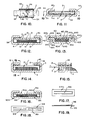
- reference numeral 601 indicates a sixth embodiment of thermal protector of this invention, with an upper plate-terminal 602, a PTC element 603, a lower plate-terminal 604, and an insulating sheet 605.
- the upper plate-terminal 602 has side walls 625 along its long side edges, that are directed away from a bottom wall 640 of the lower plate-terminal 604.
- the upper plate 602 is the same as the upper plate 502 of the embodiment shown in Figure 7, except that it is inverted.
- the lower plate 604 has side walls 642 that extend height-wise above the side walls 625 of the upper plate, with outermost margins 644 curled over the side walls 625.
- the clamping means consists of separate C springs 760 along the two long sides. If the C springs are made of a material that is not electrically conductive, the insulating sheet could be eliminated. It can be seen that the PTC element can be put in a frame of insulting sheet, as in the embodiment shown explicitly in Figures 1-3, although the plates will still need to be insulated from the C springs, hence from one another, if the C springs are conductive.
Abstract
Description
- This invention has to do with thermal protectors in which a polymeric PTC element, of the heating cable type, for example, is used. Thermal protectors of this type are already known, in which terminals are soldered to conductive foil bonded to opposite broad sides of a flat strip of PTC material. The disadvantages of such a construction are that it is labor intensive and requires careful control, that it is more or less limited in its range of response times, and that it is liable to have its characteristics affected by shear or tension forces applied to the PTC material, because the connection between the two terminals is made mechanically through the PTC material itself. Compressive forces have little effect upon the thermal characteristics of polymeric PTC material, compared with shear and tensile forces, at least within the limits of compressive force required in the device of this invention.
- One of the objects of this invention is to provide a thermal protector that is effective, has uniform thermal characteristics, can be made with a wide range of thermal responses, and can be manufactured in high volume at low cost, automatically.
- Other objects will become apparent to those skilled in the art in the light of the following description and accompanying drawing.
- In accordance with this invention, generally stated, a thermal protector is provided which includes a polymeric PTC element with broad upper and lower surfaces sandwiched between and held in intimate mechanical and electrical contact over substantially its entire broad surface with inner broad surfaces of upper and lower plate-terminals. Electrical insulation between the upper and lower plate-terminals outside the areas of contact of the plate-terminals and the PTC element insulate the upper and lower plate-terminals from one another electrically. The upper and lower plate-terminals are mechanically clamped together, in such a way that the PTC element is essentially protected against foreign external mechanical forces.
- In the preferred embodiments, the PTC element is biased into engagement with the plate-terminals continuously. Also in the preferred embodiments, the means for clamping the upper and lower plate-terminals are integral with at least one of the plate-terminals. In the preferred embodiment, terminal parts of the plate-terminals project from opposite ends of the protector, and are integral with the plate-terminals.
-
- In the drawing, Figure 1 is a top plan view of one embodiment of thermal protector of this invention;
- Figure 2 is a transverse sectional view, enlarged for purposes of illustration, of the device shown in Figure 1;
- Figure 3 is an expanded perspective view of the device shown in Figure 1;
- Figure 4 is a transverse sectional view of another embodiment;
- Figure 5 is a transverse sectional view showing a third embodiment;
- Figure 6 is a transverse sectional view showing a fourth embodiment;
- Figure 7 is a transverse sectional view showing a fifth embodiment;
- Figure 8 is a transverse sectional view showing a sixth embodiment;
- Figure 9 is a transverse sectional view showing a seventh embodiment;
- Figure 10 is a sectional view taken along the line 10-10 of Figure 11;
- Figure 11 is a transverse sectional view of a modified form of the device shown in Figures 1-3;
- Figure 12 is a transverse sectional view showing another modification of the device shown in Figures 1-3;
- Figure 13 is a transverse sectional view showing an eighth embodiment;
- Figure 14 is a transverse sectional view of yet another modification of the device shown in Figures 1-3;
- Figure 15 is a fragmentary sectional view taken along the line 15-15 of Figure 14;
- Figure 16 is a transverse sectional view showing a ninth embodiment;
- Figure 17 is a top plan view of one form of spring suitable for use in the embodiment shown in Figure 16;
- Figure 18 is a top plan view of another form of spring suitable for use in the embodiment shown in Figure 16; and
- Figure 19 is a view in side elevation showing a leaf of the spring shown in Figure 17 or of one of the leaves of the spring shown in Figure 18.
- Referring now to the drawing and particular to Figures 1-3, for one illustrative embodiment of thermal protector of this invention, reference numeral 1 indicates an assembled thermal protector, made up of four separate parts, an upper plate-
terminal 2, a PTC (positive temperature coefficient)element 3, a lower plate-terminal 4, and aninsulating sheet 5. The terms "upper" and "lower" are used merely as a matter of convenience, because the thermal protector can be oriented in any direction. - The upper plate-
terminal 2 is, in this embodiment, flat, elongated, and thin height-wise as compared with its length and width. It has anouter surface 20, aninner surface 21, parallellong side edges 22, ashort end edge 23 and a terminal part in the form of atab 24 integral with the rest of the upper plate-terminal, and projecting from the opposite end from theshort end edge 23. - The
PTC element 3 is rectangular in plan, and is also thin relative to its width and length. It is made up of a matrix orweb 30 of carbon-filled polymeric material, the broad upper and lower faces of which are covered with nickel (or other suitable conductive material)foil 31. When assembled, long side edges 33 of theelement 3 are parallel with thelong edges 22 of the upper plate-terminal 2, and end edges 34 of the PTC element are parallel with theshort end edge 23 of the upper plate-terminal, and spaced inwardly from theside edges 22, theshort end edge 23, and the root end of thetab 24. - The lower plate-
terminal 4 has the same length as the upper plate-terminal 2. The lower plate-terminal 4 has abottom wall 40, with anend edge 48 aligned with the root of theterminal tab 24, and anintegral tab 49, aligned at its root with theshort end edge 23, hence projecting from the opposite end of the thermal protector from thetab 24. Thebottom wall 40 has aninner surface 41 of the same shape but of a width greater by twice the thickness of theinsulating sheet 5 than theinner surface 21 of the upper plate-terminal 2.Side walls 42, withoverlying margins 45, extend along long sides of and are integral with thebottom wall 40. - The
insulating sheet 5 hasend frame strips 50 andside frame strips 52, defining arectangular opening 53 of a size to receive closely thePTC element 3,side walls 54 extending along and integral with theside frame strips 52, andoverlying margins 55, integral with theside walls 54. - As will be readily understood by those skilled in the art, all of the four elements that make up the thermal protector can be made in strip form and fed to a machine that will stamp, punch, form, assemble, and bend or crimp the respective parts at high speeds. The elements, as shown in the exploded view, Figure 3, are assembled by putting the insulating sheet on the inner surface of the bottom wall of the lower plate-terminal, with the sides of the insulating material projecting above the unbent sides of the lower plate-terminal, putting the PTC element within the
opening 53, framed by the frame members of the insulating sheet, placing the upper terminal on top of the PTC element, and bending theoverlying margins 45 of theside walls 42 and themargins 55 of the insulating sheet over theouter surface 20 of the upper plate-terminal. - As will be explained in connection with other embodiments, either the upper plate-terminal or the lower plate-terminal, or both, can be bowed slightly convexly with respect to the PTC element, not enough to interfere with the contact between the inner surfaces of the plate-terminals and the PTC element over substantially the full surface areas of the PTC element, but enough to give a slight continuing bias toward engagement.
- Merely by way of illustration, and not of limitation, in a thermal protector in which the distance between the short end edges of the plate-terminals and the roots of the terminal tabs is 3/4" and the width of the assembled protector, 7/16", with tabs 1/4" long, so that the overall length of the device is 1 1/4", the upper and lower plates can be made of brass, 0.020" thick, the insulating sheet can be Nomex paper 0.005" thick, and the PTC element, made up of the carbon-loaded polymer matrix 0.010" thick and each layer of the nickel foil .001" thick for a total thickness of the PTC element of 0.12". This construction, for a motor protector, provides a 12-15 second delay, which is what is desired. The soldered type provides only about 5 seconds delay. By increasing the mass of the PTC element in the present device, one can obtain various response times. It can be seen that in the construction of the thermal protector of this invention, the polymeric material can be made as thick as is desired, because it takes no stresses in shear or tension, all of those forces being exerted upon the plate-terminals.
- All of the embodiments described hereinafter can be considered, for purposes of description, as having the same general shape and size as the embodiment described above, with terminal tabs integral with their respective plate-terminals. The PTC element can also be considered the same, although for purposes of illustration and to indicate that a range of thicknesses can be employed, the element is shown as being of varying thickness in the various embodiments.
- Referring now to Figure 4,
reference numeral 201 indicates a second embodiment of thermal protector. Theprotector 201 has an upper plate-terminal 202, aPTC element 203, a lower plate-terminal 204, and an insulating sheet 205. In this embodiment, the upper plate 202 can be the same as theupper plate 2 of the first embodiment. In this embodiment, the lower plate-terminal 204 has a bottom wall 240 andside walls 242. However, theside walls 242 are stepped outwardly, to provide aninterior ledge 243. The insulating sheet 205 may be provided with ariser margin 256, although that is not essential. - The bottom wall 240 in this embodiment is bowed so that an
inner surface 241 of the bottom wall is convex with respect to the PTC element. The bow in the illustration in Figure 4 is much exaggerated. In practice, the bow will be only two or three thousandths of an inch, enough to bias the PTC element continuously into engagement, even if there is a slight distortion of the element with continued use, but not enough to interfere with substantially uniform contact over the entire face of the PTC element with theinner surface 241. It can be seen that the gap shown in Figure 4 between the upper plate-terminal inner surface and the insulated sheet overlying the ledge can be reduced to nothing, in which case, all of the crimping force ofoverlying margins 245 will be exerted on the plate and insulation, and none on the PTC element. - Referring now to Figure 5, reference numeral 301 indicates a third embodiment of thermal protector of this invention, with an upper plate-
terminal 302, a PTC element 303, a lower plate-terminal 304 and an insulatingsheet 305. The upper plate-terminal has an outer surface 320 and aninner surface 321. It also has amargin 325 along one long edge. The lower plate-terminal has aninner surface 341, anouter surface 343 and asingle margin 345 along one long edge. Theupper plate margin 325 is curled around a long edge of the lower plate, and thelower plate margin 345 is curled around a long edge of theupper plate 302. As in the other embodiments, the insulating sheet lies between the upper and lower plates in every area in which mechanical and electrical contact between the two plates might otherwise occur. A virtue of this embodiment is that the upper and lower plate-terminals can be identical parts, requiring only one die or roll for both. - Referring now to Figure 6,
reference numeral 401 indicates a fourth embodiment of thermal protector of this invention, with an upper plate-terminal 402, aPTC element 403, a lower plate-terminal 404, and an insulatingsheet 405. The view in this Figure, as can easily be seen, is upside down from that of the embodiments shown in Figures 1 and 4. The protector of this embodiment is identical with that of the embodiment shown in Figures 1 through 3 except that the side walls of the lower plate-terminal are curled around the long edges of the upper plate,outer edges 446 ofoverlying margins 445 bearing upon the outside surface of theupper plate 402, and leaving aclearance gap 447 between the rest of theoverlying margin 445 and the plate. In this way, the overlying margins act as springs, biasing the upper plate toward the PTC element and the PTC element toward the inside surface of the lower plate. - Referring now to Figure 7,
reference numeral 501 indicates a fifth embodiment of thermal protector of this invention, with an upper plate-terminal 502, aPTC element 503, a lower plate-terminal 504 and an insulatingsheet 505. The upper plate 502 has an outer surface 520, an inner surface 521,side walls 525 extending along the long edges of the plate, and side wallouter edges 526. Thelower plate 504 has abottom wall 540 with an inner surface 541, aninner side wall 542, anintermediate side wall 543 and anouter margin 544. As can be seen from the drawing, theintermediate side wall 543 and theouter margin 544 define between them a channel into which theside wall 525 of the upper plate extends, and into which it is crimped. In this embodiment, none of the crimping pressure need be transmitted to the PTC element. By the same token, it is desirable to put a small bow in one or both of theplates 502 and 504, so as to exert a constant compressive bias on the PTC element. - Referring now to Figure 8,
reference numeral 601 indicates a sixth embodiment of thermal protector of this invention, with an upper plate-terminal 602, aPTC element 603, a lower plate-terminal 604, and an insulating sheet 605. The upper plate-terminal 602 hasside walls 625 along its long side edges, that are directed away from abottom wall 640 of the lower plate-terminal 604. In this respect the upper plate 602 is the same as the upper plate 502 of the embodiment shown in Figure 7, except that it is inverted. Thelower plate 604 hasside walls 642 that extend height-wise above theside walls 625 of the upper plate, withoutermost margins 644 curled over theside walls 625. It can be seen that in this embodiment, clamping pressure can be exerted both against the sides of theside walls 625, and against the outer surface of the upper plate, in a spring-like arrangement if desired. In the embodiment shown, thebottom wall 640 is bowed convexly with respect to the PTC element to provide additional compressive bias against the PTC element. As in all of the embodiments, the insulating sheet is interposed between the upper and lower plates wherever contact of the two plates is possible. - Referring now to Figure 9, reference numeral 701 indicates a seventh embodiment of thermal protector of this invention, with an upper plate-terminal 702, a
PTC element 703, a lower plate-terminal 704, and an insulatingsheet 705. In this embodiment, the upper and lower plates can be identical, with an upper plate outer surface 720 and an upper plateinner surface 721, a lower plateouter surface 740 and a lower plate inner surface 741, and the PTC element sandwiched between them. The PTC element is shown as extending to the side edges of the plates, and the insulating sheet takes the form of separate U-shaped strips, although, as can be seen, one pair of legs of the U-shaped strips could be joined across its particular outside surface, to simplify manufacturing, for example. In this embodiment, the clamping means consists of separate C springs 760 along the two long sides. If the C springs are made of a material that is not electrically conductive, the insulating sheet could be eliminated. It can be seen that the PTC element can be put in a frame of insulting sheet, as in the embodiment shown explicitly in Figures 1-3, although the plates will still need to be insulated from the C springs, hence from one another, if the C springs are conductive. - Referring now to Figures 10 and 11, because the device illustrated is a modification of the device shown in Figures 1 through 3, all of the common elements are indicated by the same reference numerals. The only difference is in the provision in the upper plate-
terminal 2 of notches 6 on either side of the plate-terminal, and indentations 7 in theside walls 42 of the lower plate-terminal andside walls 54 of the insulatingsheet 5, producing projections 8 in the inner surface of those walls extending into the notches 6. The projections 8 lock the upper and lower plate-terminals against relative movement longitudinally with respect to one another. - Referring now to Figure 12 for another modification of the device shown in Figures 1 through 3, the difference in this embodiment lies in the provision of securing
material 15 bonded to the upper andlower surfaces 31 of thePTC element 3, and to theinner surface 21 of the upper plate-terminal 2 and theinner surface 41 of the lower plate-terminal 4. The material 12 can take the form of solder or conductive epoxy. In the case of the solder, a layer of solder can be put on theinner surfaces outer surfaces 31, the device assembled, and run through an oven to melt the solder and bond the PTC element to the upper and lower plate-terminals. Epoxy can be applied conventionally. The modifications of Figures 11 and 12 can be combined, because it is undesirable to transmit any force in shear to the PTC element, as has been pointed out heretofore. - Referring now to Figure 13, reference numeral 801 indicates an eighth embodiment of thermal protector. The thermal protector 801 has an upper plate-terminal 802, a
PTC element 803, a lower plate-terminal 804 and an insulatingsheet 805. The lower plate-terminal 804 has abottom wall 840, side walls 842 and, integral with the side walls 842, out-turned flanges 843. The upper plate-terminal 802 hasside walls 822 andunderlying margins 825 tightly engaging the flanges 843, with insulatingsheet 805 sandwiched between them. In this embodiment, a strip of resilient electricallyconductive rubber 815 is interposed between aninner surface 821 of the upper plate-terminal 802 and anupper surface 831 of thePTC element 803, and is compressed therebetween. The resilience of the rubber "spring" 815 insures constant electrical contact between thePTC element 803 and the upper and lower plate-terminals 802 and 804. - Referring now to Figures 14 and 15 for yet another modification of the device shown in Figures 1 through 3, the difference in construction between the protector shown in Figures 1 through 3 and that of Figures 14 and 15 is the provision of a
spring 15 between theoverlying margins 45 of the lower plate-terminal 4 and theoverlying margins 55 of the insulatingsheet 5, so that the upper plate-terminal 2 is continuously spring biased toward and into contact with the PTC element, which in turn is biased against the inner surface of the lower plate-terminal 4. - Referring now to Figure 16,
reference numeral 901 indicates a ninth embodiment, which resembles the embodiment shown in Figures 1 through 3 but for the provision of aspring 915, sandwiched between aPTC element 903 and aninner surface 941 of a lower plate-terminal 904. Thespring 915 is made of electrically conductive, stiffly springy material. In the embodiment shown in Figures 16, 17 and 19, the spring has asingle leaf 916 stuck up symmetrically along the long axis of the rectangular body of the spring. In Figure 18, another embodiment ofspring 918 is shown, in which two, facing leaves 919 are struck up from the body of the spring. Thesprings - Numerous variations in the construction of the thermal protector of this invention, within the scope of the appended claims, will occur to those skilled in the art in the light of the foregoing disclosure. Merely by way of example, both upper and lower plates may be bowed, and springy clamping means may be employed with bowed plates as well. Other expedients may be used to prevent longitudinal displacement of the upper and lower plates with respect to one another, such, for example, as by dimpling overlying margins, or by providing a projecting finger on the short ends of the plates, and bending it down, over a corresponding piece of insulating, over the end edge between the side edge and the tab. The tabs can be made in any length and any width desired, and may be punched or otherwise formed to take conductors to which they are to be attached. The tabs can be offset from one another laterally, or bent in opposite directions, and formed to project from the same end of the thermal protector. It will be seen that because the PTC element is not bonded to the plate-terminals except in the embodiment shown in Figure 12, it is subjected only to compressive force, which, as has been pointed out, does not affect the thermal characteristics of the PTC element as much as forces in shear or tension. In the embodiment in which it is bonded, provision is made for preventing relative displacement of the upper and lower plate-terminals. Other configurations of the plates, clamping means, PTC elements and insulating sheet will be readily apparent, that embody the concept common to the embodiments described of a simple thermal protector utilizing a polymeric PTC element in such a way that the element is subjected only to compressive forces, easy to manufacture, requiring few parts, and very little labor. The variations described are merely illustrative.
Claims (21)
Applications Claiming Priority (2)
| Application Number | Priority Date | Filing Date | Title |
|---|---|---|---|
| US848161 | 1986-04-04 | ||
| US06/848,161 US4698614A (en) | 1986-04-04 | 1986-04-04 | PTC thermal protector |
Publications (3)
| Publication Number | Publication Date |
|---|---|
| EP0240447A2 true EP0240447A2 (en) | 1987-10-07 |
| EP0240447A3 EP0240447A3 (en) | 1990-03-07 |
| EP0240447B1 EP0240447B1 (en) | 1994-05-04 |
Family
ID=25302514
Family Applications (1)
| Application Number | Title | Priority Date | Filing Date |
|---|---|---|---|
| EP87630025A Expired - Lifetime EP0240447B1 (en) | 1986-04-04 | 1987-02-26 | PTC thermal protector |
Country Status (5)
| Country | Link |
|---|---|
| US (1) | US4698614A (en) |
| EP (1) | EP0240447B1 (en) |
| JP (1) | JPS62239501A (en) |
| CA (1) | CA1258139A (en) |
| DE (1) | DE3789723T2 (en) |
Cited By (10)
| Publication number | Priority date | Publication date | Assignee | Title |
|---|---|---|---|---|
| EP0319450A2 (en) * | 1987-12-03 | 1989-06-07 | Emerson Electric Co. | Polymer type PTC assembly |
| EP0333906A1 (en) * | 1988-03-25 | 1989-09-27 | David & Baader DBK Spezialfabrik elektrischer Apparate und Heizwiderstände GmbH | PTC heating resistor |
| EP0487920A1 (en) * | 1990-10-30 | 1992-06-03 | Asea Brown Boveri Ab | PTC element |
| EP0516112A2 (en) * | 1991-05-28 | 1992-12-02 | Chiung-Hsiang Yang | PTC semiconductor heating means having fully clad casing |
| EP0573691A1 (en) * | 1992-06-11 | 1993-12-15 | David & Baader DBK Spezialfabrik elektrischer Apparate und Heizwiderstände GmbH | Method for producing a PTC heating element |
| EP0650243A1 (en) * | 1993-10-22 | 1995-04-26 | Johnson Electric S.A. | Brush assembly |
| DE10360159A1 (en) * | 2003-12-20 | 2005-07-21 | Eichenauer Heizelemente Gmbh & Co. Kg | Profile tube and method for clamping functional elements in such |
| EP2395295A1 (en) * | 2010-06-11 | 2011-12-14 | Behr GmbH & Co. KG | Heat exchanger |
| EP3598847A1 (en) * | 2018-07-18 | 2020-01-22 | Eberspächer catem GmbH & Co. KG | Heat-generating element and method for producing the same |
| GB2618837A (en) * | 2022-05-19 | 2023-11-22 | Finar Module Sagl | enclosure for a power resistor assembly |
Families Citing this family (41)
| Publication number | Priority date | Publication date | Assignee | Title |
|---|---|---|---|---|
| JPH0690962B2 (en) * | 1986-03-31 | 1994-11-14 | 日本メクトロン株式会社 | Method for manufacturing PTC element |
| US5010264A (en) * | 1988-09-09 | 1991-04-23 | Mabuchi Motor Co., Ltd. | Miniature motor having positive-coefficient thermistor |
| GB2244868B (en) * | 1990-06-05 | 1994-03-30 | Johnson Electric Sa | Temperature control in an electric motor |
| GB9109194D0 (en) * | 1991-04-29 | 1991-06-19 | Johnson Electric Sa | A thermally protected electric motor |
| US5170146A (en) * | 1991-08-01 | 1992-12-08 | Motorola, Inc. | Leadless resistor |
| SE469250B (en) * | 1991-10-07 | 1993-06-07 | Asea Brown Boveri | DEVICE FOR OVERLOAD AND SHORT-CUT PROTECTION IN ELECTRICAL EQUIPMENT |
| US5287083A (en) * | 1992-03-30 | 1994-02-15 | Dale Electronics, Inc. | Bulk metal chip resistor |
| DE4441280C2 (en) * | 1994-11-19 | 1998-08-27 | Asea Brown Boveri | PTC thermistor and device for current limitation with at least one PTC thermistor |
| US5668521A (en) * | 1995-03-22 | 1997-09-16 | Littelfuse, Inc. | Three piece female blade fuse assembly having fuse link terminal with a clip receiving portion |
| US5945903A (en) * | 1995-06-07 | 1999-08-31 | Littelfuse, Inc. | Resettable automotive circuit protection device with female terminals and PTC element |
| US5663861A (en) * | 1995-06-07 | 1997-09-02 | Littelfuse, Inc. | Resettable automotive circuit protection device |
| DE69606310T2 (en) * | 1995-08-15 | 2001-04-05 | Bourns Multifuse Hong Kong Ltd | SURFACE MOUNTED CONDUCTIVE COMPONENTS AND METHOD FOR PRODUCING THE SAME |
| TW309619B (en) * | 1995-08-15 | 1997-07-01 | Mourns Multifuse Hong Kong Ltd | |
| US5939968A (en) * | 1996-06-19 | 1999-08-17 | Littelfuse, Inc. | Electrical apparatus for overcurrent protection of electrical circuits |
| US5808538A (en) * | 1996-06-19 | 1998-09-15 | Littelfuse, Inc. | Electrical apparatus for overcurrent protection of electrical circuits |
| US6215388B1 (en) | 1996-09-27 | 2001-04-10 | Therm-Q-Disc, Incorporated | Parallel connected PTC elements |
| US6020808A (en) * | 1997-09-03 | 2000-02-01 | Bourns Multifuse (Hong Kong) Ltd. | Multilayer conductive polymer positive temperature coefficent device |
| US6128168A (en) | 1998-01-14 | 2000-10-03 | General Electric Company | Circuit breaker with improved arc interruption function |
| US6236302B1 (en) | 1998-03-05 | 2001-05-22 | Bourns, Inc. | Multilayer conductive polymer device and method of manufacturing same |
| US6242997B1 (en) | 1998-03-05 | 2001-06-05 | Bourns, Inc. | Conductive polymer device and method of manufacturing same |
| US6172591B1 (en) | 1998-03-05 | 2001-01-09 | Bourns, Inc. | Multilayer conductive polymer device and method of manufacturing same |
| JPH11340007A (en) * | 1998-05-22 | 1999-12-10 | Murata Mfg Co Ltd | Negative temperature coefficient thermister and electronic duplicator |
| JP2002526911A (en) | 1998-09-25 | 2002-08-20 | ブアンズ・インコーポレイテッド | A two-stage method for producing positive temperature coefficient polymeric materials |
| US6144540A (en) | 1999-03-09 | 2000-11-07 | General Electric Company | Current suppressing circuit breaker unit for inductive motor protection |
| US6157286A (en) | 1999-04-05 | 2000-12-05 | General Electric Company | High voltage current limiting device |
| DE29911713U1 (en) * | 1999-07-06 | 2000-08-31 | Eichenauer Gmbh & Co Kg F | Heating device for fluids |
| US6429533B1 (en) | 1999-11-23 | 2002-08-06 | Bourns Inc. | Conductive polymer device and method of manufacturing same |
| EP1213728A3 (en) * | 2000-11-27 | 2005-10-26 | Eaton Corporation | Current-limiting device |
| EP1467599B1 (en) * | 2003-04-12 | 2008-11-26 | Eichenauer Heizelemente GmbH & Co.KG | Device for the admission of ceramic heating elements and procedure for the production of such |
| US7119655B2 (en) * | 2004-11-29 | 2006-10-10 | Therm-O-Disc, Incorporated | PTC circuit protector having parallel areas of effective resistance |
| US20060273876A1 (en) * | 2005-06-02 | 2006-12-07 | Pachla Timothy E | Over-temperature protection devices, applications and circuits |
| KR101076191B1 (en) * | 2008-12-05 | 2011-10-21 | 현대자동차주식회사 | PTC Rod Assembly and PTC Heater Using the Same |
| JP5777898B2 (en) * | 2011-02-08 | 2015-09-09 | 株式会社ミツバ | Electric motor and method for manufacturing electric motor |
| DE102012013770A1 (en) * | 2012-07-11 | 2014-01-16 | Eberspächer Catem Gmbh & Co. Kg | Heat generating element |
| DE102012107985B4 (en) * | 2012-08-29 | 2023-06-22 | Borgwarner Ludwigsburg Gmbh | heater |
| JP6590501B2 (en) * | 2015-03-27 | 2019-10-16 | Fdk株式会社 | External PTC element and cylindrical battery |
| DE102017206487B4 (en) * | 2017-04-18 | 2020-07-02 | Eberspächer Catem Gmbh & Co. Kg | PTC heating element and method for its production |
| DE102018101453A1 (en) * | 2018-01-23 | 2019-07-25 | Borgwarner Ludwigsburg Gmbh | Heating device and method for producing a heating rod |
| CN110243077B (en) * | 2019-06-04 | 2024-01-02 | 浙江银轮机械股份有限公司 | Heat transfer shell for mounting PTC heating sheet |
| DE102021112603A1 (en) | 2021-05-14 | 2022-11-17 | Stego-Holding Gmbh | Heater and method of manufacturing a heater |
| DE102022107554A1 (en) | 2022-03-30 | 2023-10-05 | Eberspächer Catem Gmbh & Co. Kg | PTC heater and electric heater comprising one |
Citations (3)
| Publication number | Priority date | Publication date | Assignee | Title |
|---|---|---|---|---|
| DE2845965A1 (en) * | 1978-10-21 | 1980-04-24 | Eichenauer Fa Fritz | ELECTRIC RESISTANCE HEATING ELEMENT |
| GB1583771A (en) * | 1976-03-18 | 1981-02-04 | Fast Heat Element Mfg Co | Electric heaters having resistance wire embedded in ceramic |
| US4331860A (en) * | 1979-12-03 | 1982-05-25 | Fritz Eichenauer Gmbh & Co. Kg | Electrical resistance heating element |
Family Cites Families (2)
| Publication number | Priority date | Publication date | Assignee | Title |
|---|---|---|---|---|
| US4395623A (en) * | 1980-03-04 | 1983-07-26 | Murata Manufacturing Co., Ltd. | Self-regulating electric heater |
| US4399423A (en) * | 1982-03-29 | 1983-08-16 | Texas Instruments Incorporated | Miniature electric circuit protector |
-
1986
- 1986-04-04 US US06/848,161 patent/US4698614A/en not_active Expired - Lifetime
-
1987
- 1987-02-26 DE DE3789723T patent/DE3789723T2/en not_active Expired - Fee Related
- 1987-02-26 EP EP87630025A patent/EP0240447B1/en not_active Expired - Lifetime
- 1987-03-30 JP JP62079521A patent/JPS62239501A/en active Pending
- 1987-04-02 CA CA000533718A patent/CA1258139A/en not_active Expired
Patent Citations (3)
| Publication number | Priority date | Publication date | Assignee | Title |
|---|---|---|---|---|
| GB1583771A (en) * | 1976-03-18 | 1981-02-04 | Fast Heat Element Mfg Co | Electric heaters having resistance wire embedded in ceramic |
| DE2845965A1 (en) * | 1978-10-21 | 1980-04-24 | Eichenauer Fa Fritz | ELECTRIC RESISTANCE HEATING ELEMENT |
| US4331860A (en) * | 1979-12-03 | 1982-05-25 | Fritz Eichenauer Gmbh & Co. Kg | Electrical resistance heating element |
Cited By (16)
| Publication number | Priority date | Publication date | Assignee | Title |
|---|---|---|---|---|
| EP0319450A2 (en) * | 1987-12-03 | 1989-06-07 | Emerson Electric Co. | Polymer type PTC assembly |
| EP0319450A3 (en) * | 1987-12-03 | 1989-11-23 | Emerson Electric Co. | Polymer type ptc assembly |
| EP0333906A1 (en) * | 1988-03-25 | 1989-09-27 | David & Baader DBK Spezialfabrik elektrischer Apparate und Heizwiderstände GmbH | PTC heating resistor |
| EP0487920A1 (en) * | 1990-10-30 | 1992-06-03 | Asea Brown Boveri Ab | PTC element |
| EP0516112A2 (en) * | 1991-05-28 | 1992-12-02 | Chiung-Hsiang Yang | PTC semiconductor heating means having fully clad casing |
| EP0516112A3 (en) * | 1991-05-28 | 1993-06-02 | Chiung-Hsiang Yang | Ptc semiconductor heating means having fully clad casing |
| EP0573691A1 (en) * | 1992-06-11 | 1993-12-15 | David & Baader DBK Spezialfabrik elektrischer Apparate und Heizwiderstände GmbH | Method for producing a PTC heating element |
| EP0650243A1 (en) * | 1993-10-22 | 1995-04-26 | Johnson Electric S.A. | Brush assembly |
| DE10360159A1 (en) * | 2003-12-20 | 2005-07-21 | Eichenauer Heizelemente Gmbh & Co. Kg | Profile tube and method for clamping functional elements in such |
| US7332693B2 (en) | 2003-12-20 | 2008-02-19 | Eichenauer Heizelemente Gmbh & Co. Kg | Tube and method for bracing functional elements in the same |
| EP2395295A1 (en) * | 2010-06-11 | 2011-12-14 | Behr GmbH & Co. KG | Heat exchanger |
| EP3598847A1 (en) * | 2018-07-18 | 2020-01-22 | Eberspächer catem GmbH & Co. KG | Heat-generating element and method for producing the same |
| CN110740527A (en) * | 2018-07-18 | 2020-01-31 | 埃贝赫卡腾有限两合公司 | Heating element and method for manufacturing the same |
| CN110740527B (en) * | 2018-07-18 | 2022-08-30 | 埃贝赫卡腾有限两合公司 | Heating element and method for manufacturing the same |
| GB2618837A (en) * | 2022-05-19 | 2023-11-22 | Finar Module Sagl | enclosure for a power resistor assembly |
| WO2023222906A1 (en) * | 2022-05-19 | 2023-11-23 | Finar Module Sagl | Power resistor device |
Also Published As
| Publication number | Publication date |
|---|---|
| DE3789723T2 (en) | 1994-08-18 |
| CA1258139A (en) | 1989-08-01 |
| US4698614A (en) | 1987-10-06 |
| DE3789723D1 (en) | 1994-06-09 |
| EP0240447A3 (en) | 1990-03-07 |
| JPS62239501A (en) | 1987-10-20 |
| EP0240447B1 (en) | 1994-05-04 |
Similar Documents
| Publication | Publication Date | Title |
|---|---|---|
| US4698614A (en) | PTC thermal protector | |
| US5854471A (en) | Apparatus using a thermistor with a positive temperature coefficient | |
| US4169641A (en) | Connector clip for flat cable | |
| JPS62165883A (en) | Electric terminal | |
| EP0507425B1 (en) | Electrothermal relay with film heating element | |
| EP0728364B1 (en) | Electrical assembly | |
| US3840840A (en) | Flat conductor cable connector | |
| JPS60112281A (en) | Heater | |
| US5951303A (en) | Contact strip for printed circuit boards | |
| US5909168A (en) | PTC conductive polymer devices | |
| CA1290465C (en) | Polymer type ptc assembly | |
| JPH0817484A (en) | Pressure contacting terminal structure | |
| GB2357638A (en) | An electrical terminal for a window | |
| US819060A (en) | Terminal strip. | |
| JPS5841668Y2 (en) | twin tab receptacle | |
| JP3617542B2 (en) | Surface mount structure of ceramic electronic components | |
| EP0251318A2 (en) | Snap-action heat responsive device | |
| JP7315373B2 (en) | Pressure contact terminal and method for manufacturing pressure contact terminal | |
| JPS5832216Y2 (en) | Switch cord connection terminal board device | |
| JP2001076781A (en) | Connection terminal of flat circuit body | |
| KR830000512Y1 (en) | Serial cathode structure | |
| JPH0621184Y2 (en) | Insulation displacement connector | |
| JPH08250306A (en) | Positive temperature coefficient thermistor heater | |
| JPH0623202U (en) | PTC thermistor device | |
| JPH06283306A (en) | Positive temperature coefficient thermistor device |
Legal Events
| Date | Code | Title | Description |
|---|---|---|---|
| PUAI | Public reference made under article 153(3) epc to a published international application that has entered the european phase |
Free format text: ORIGINAL CODE: 0009012 |
|
| AK | Designated contracting states |
Kind code of ref document: A2 Designated state(s): DE FR GB NL |
|
| PUAL | Search report despatched |
Free format text: ORIGINAL CODE: 0009013 |
|
| AK | Designated contracting states |
Kind code of ref document: A3 Designated state(s): DE FR GB NL |
|
| 17P | Request for examination filed |
Effective date: 19900514 |
|
| 17Q | First examination report despatched |
Effective date: 19920423 |
|
| GRAA | (expected) grant |
Free format text: ORIGINAL CODE: 0009210 |
|
| AK | Designated contracting states |
Kind code of ref document: B1 Designated state(s): DE FR GB NL |
|
| ET | Fr: translation filed | ||
| REF | Corresponds to: |
Ref document number: 3789723 Country of ref document: DE Date of ref document: 19940609 |
|
| PLBE | No opposition filed within time limit |
Free format text: ORIGINAL CODE: 0009261 |
|
| STAA | Information on the status of an ep patent application or granted ep patent |
Free format text: STATUS: NO OPPOSITION FILED WITHIN TIME LIMIT |
|
| 26N | No opposition filed | ||
| PGFP | Annual fee paid to national office [announced via postgrant information from national office to epo] |
Ref country code: GB Payment date: 19960119 Year of fee payment: 10 |
|
| PGFP | Annual fee paid to national office [announced via postgrant information from national office to epo] |
Ref country code: NL Payment date: 19960123 Year of fee payment: 10 |
|
| PGFP | Annual fee paid to national office [announced via postgrant information from national office to epo] |
Ref country code: DE Payment date: 19960124 Year of fee payment: 10 |
|
| PGFP | Annual fee paid to national office [announced via postgrant information from national office to epo] |
Ref country code: FR Payment date: 19960201 Year of fee payment: 10 |
|
| PG25 | Lapsed in a contracting state [announced via postgrant information from national office to epo] |
Ref country code: GB Effective date: 19970226 |
|
| PG25 | Lapsed in a contracting state [announced via postgrant information from national office to epo] |
Ref country code: NL Effective date: 19970901 |
|
| GBPC | Gb: european patent ceased through non-payment of renewal fee |
Effective date: 19970226 |
|
| PG25 | Lapsed in a contracting state [announced via postgrant information from national office to epo] |
Ref country code: FR Effective date: 19971030 |
|
| PG25 | Lapsed in a contracting state [announced via postgrant information from national office to epo] |
Ref country code: DE Effective date: 19971101 |
|
| NLV4 | Nl: lapsed or anulled due to non-payment of the annual fee |
Effective date: 19970901 |
|
| REG | Reference to a national code |
Ref country code: FR Ref legal event code: ST |