EP0516112A2 - PTC semiconductor heating means having fully clad casing - Google Patents
PTC semiconductor heating means having fully clad casing Download PDFInfo
- Publication number
- EP0516112A2 EP0516112A2 EP92109005A EP92109005A EP0516112A2 EP 0516112 A2 EP0516112 A2 EP 0516112A2 EP 92109005 A EP92109005 A EP 92109005A EP 92109005 A EP92109005 A EP 92109005A EP 0516112 A2 EP0516112 A2 EP 0516112A2
- Authority
- EP
- European Patent Office
- Prior art keywords
- casing
- plate
- socket
- pole
- longitudinal
- Prior art date
- Legal status (The legal status is an assumption and is not a legal conclusion. Google has not performed a legal analysis and makes no representation as to the accuracy of the status listed.)
- Granted
Links
Images


Classifications
-
- H—ELECTRICITY
- H05—ELECTRIC TECHNIQUES NOT OTHERWISE PROVIDED FOR
- H05B—ELECTRIC HEATING; ELECTRIC LIGHT SOURCES NOT OTHERWISE PROVIDED FOR; CIRCUIT ARRANGEMENTS FOR ELECTRIC LIGHT SOURCES, IN GENERAL
- H05B3/00—Ohmic-resistance heating
- H05B3/40—Heating elements having the shape of rods or tubes
- H05B3/42—Heating elements having the shape of rods or tubes non-flexible
-
- H—ELECTRICITY
- H01—ELECTRIC ELEMENTS
- H01C—RESISTORS
- H01C1/00—Details
- H01C1/02—Housing; Enclosing; Embedding; Filling the housing or enclosure
-
- H—ELECTRICITY
- H01—ELECTRIC ELEMENTS
- H01C—RESISTORS
- H01C1/00—Details
- H01C1/14—Terminals or tapping points or electrodes specially adapted for resistors; Arrangements of terminals or tapping points or electrodes on resistors
- H01C1/1406—Terminals or electrodes formed on resistive elements having positive temperature coefficient
-
- H—ELECTRICITY
- H05—ELECTRIC TECHNIQUES NOT OTHERWISE PROVIDED FOR
- H05B—ELECTRIC HEATING; ELECTRIC LIGHT SOURCES NOT OTHERWISE PROVIDED FOR; CIRCUIT ARRANGEMENTS FOR ELECTRIC LIGHT SOURCES, IN GENERAL
- H05B3/00—Ohmic-resistance heating
- H05B3/10—Heater elements characterised by the composition or nature of the materials or by the arrangement of the conductor
- H05B3/12—Heater elements characterised by the composition or nature of the materials or by the arrangement of the conductor characterised by the composition or nature of the conductive material
- H05B3/14—Heater elements characterised by the composition or nature of the materials or by the arrangement of the conductor characterised by the composition or nature of the conductive material the material being non-metallic
-
- H—ELECTRICITY
- H05—ELECTRIC TECHNIQUES NOT OTHERWISE PROVIDED FOR
- H05B—ELECTRIC HEATING; ELECTRIC LIGHT SOURCES NOT OTHERWISE PROVIDED FOR; CIRCUIT ARRANGEMENTS FOR ELECTRIC LIGHT SOURCES, IN GENERAL
- H05B2203/00—Aspects relating to Ohmic resistive heating covered by group H05B3/00
- H05B2203/02—Heaters using heating elements having a positive temperature coefficient
Definitions
- U. S. Patent 4,037,082 to a Positive Temperature Coefficient Semiconductor Heating Device invented by Tamada et al. discloses an arrangement of components for constructing a heating device employing a plurality of positive temperature coefficient semiconductor (PTCS) heating elements as a PTCS heating element, upper and lower insulating plates, a heat emission plate and a case for entirely covering the layers of the PTCS heating element and the upper and lower insulating plates.
- PTCS positive temperature coefficient semiconductor
- the present inventor has found the drawbacks of such a conventional PTC heating device, and invented the present fully clad PTC heating means.
- an electric heater including a plurality of positive-temperature-coefficient (PTC) semiconductor heating elements longitudinally embedded in a longitudinal thermally conductive casing which is also electrically conductive and generally formed as a hollow rectangular column, an electrical conductive plate held in the casing as packed by an electrical insulating plate positioned in between the casing and the electrical conductive plate, a first pole connector connected to a positive pole of a power source provided on a right end portion of the casing for electrically connecting the electrical conductive plate and connecting a lower conducting surface of each PTC semiconductor heating element, a second pole connector connected to a second pole of the power source provided on a left end portion of the casing for electrically connecting the thermally conductive casing and connecting an upper conducting surface of each PTC semiconductor heating element, and a plurality of heat-exchange plates juxtapositionally fixed on the casing for dissipating heat outwardly exerted by the plurality of PTC heating elements.
- PTC positive-temperature-coefficient
- Another object of the present invention is to provide an electric heater having the first pole connector electrically connecting the first pole of the power source, and a lower electrical conductive plate and the lower conducting surface of each PTC semiconductor heating element; and the second pole connector electrically connecting the second pole of the power source, and an upper electrical conductive plate and the upper conducting surface of each PTC semiconductor heating element, the two electrical conductive plates and the PTC semiconductor heating elements being positioned in the longitudinal thermal conductive casing packed by an upper and a lower electrical insulating plate in the casing.
- Still another object of the present invention is to provide an electric heater with a fully clad protective casing for a tightly internal connection of all elements in construction of the heater for enhancing its safety, stability, and heating efficiency.
- the present invention comprises: a longitudinal thermal and electrical conductive casing 1, an electrical insulating plate 2, an electrical conductive plate 3, a plurality of positive-temperature-coefficient (PTC) semiconductor heating elements 4 made of ceramic semiconductor materials, a first pole connector 5 electrically connectable to a first pole of a power source, a second pole connector 6 electrically connectable to a second pole of the power source, and a plurality of heat-exchange plates or fins 7 juxtapositionally embedded on the casing 1.
- PTC positive-temperature-coefficient
- the longitudinal thermally and electrically conductive casing 1 defines a generally rectangular cross-section hollow column 10 having an upper longitudinal plate 12 horizontally forming the upper portion of the casing 1, a lower longitudinal plate 13 horizontally forming the lower portion of the casing 2 parallel to the upper longitudinal plate 12, a first side plate 14 and a second side plate 15 respectively vertically formed on two opposite sides of the casing 1, each side plate 14 or 15 being perpendicular to the upper longitudinal plate 12 and defining a rectangular through hole 11 formed through the hollow column 10; a first socket 16 formed in a first end opening of the hollow column 10; a second socket 17 formed in a second end opening of the hollow column 10 opposite to the first socket 16; a plurality of protrusions 18 downwardly protruded from two opposite end portions of the upper longitudinal plate 12 proximate the two sockets 16, 17; and a limiting stopper 19 formed on one end portion of the upper longitudinal plate 12.
- Each side plate 14 or 15 is longitudinally formed with a corrugated groove 141 or 151 as shown in Figure 3 serving as a buffer for absorbing any deformation concentrated to the groove caused by pressing the casing 1 to tightly assemble the heating elements 4, the conductive plate 3, the insulating plate 2 within the casing 1.
- the shape of the hollow column 10 may be modified to be a cylindrical column, or any other polygonal shapes, which are not limited in this invention, but is preferably a rectangular column as shown in the figures.
- the electrically insulating plate 2 is made of electrical insulative materials with suitable thermal conductivity, for instance, a silicon rubber or a polycarbonate layer, having a cross section generally U-shaped; and includes: a longitudinal bottom plate 21 horizontally overlain on an inside surface of the lower longitudinal plate 13, a first and a second side extension 22, 23 longitudinally protruded upwardly from two opposite sides of the longitudinal bottom plate 21 to be retained between the upper and the lower longitudinal plates 12, 13 as shown in Figure 3.
- the electrically conductive plate 3 made of electrical conductive material includes: a longitudinal holding plate 31 horizontally overlain on the bottom plate 21 of the electrically insulating plate 2 having a plurality of partitioning projections 311 transversely formed and equally spaced on the longitudinal holding plate 31 for separately positioning each PTC semiconductor heating element 4 in between two neighbouring projections 311 as shown in Figure 2; a first side edge portion 32 and a second side edge portion 33 protruded upwardly on two opposite sides of the longitudinal holding plate 31 for transversely confining each heating element within the two side edge portions 32, 33; and an engaging end plate 34 protruded outwardly from the holding plate 31 proximate the first socket 16 of the casing 1 having a stem hole 341 formed in the engaging end plate 34, an arcuate portion 35 arcuately bent on the end plate 34 and a slot 36 cut in a central portion of the arcuate portion 35 of the end plate 34.
- Each PTC semiconductor heating element 4 includes a lower conducting surface 41 contacting the electrical conductive plate 3 and an upper conducting surface 42 contacting the upper longitudinal plate 12 of the casing 1 as shown in Figures 2, 3.
- the first pole connector 5 includes: a first connecting plate 51 having a first central hole 511 formed in the plate 51 and having a first pole pin 52 with a pin hole 521 formed in the pin 52 protruded outwardly from the first connecting plate 51 for connecting a first pole of a power source (not shown), a first terminal plug 54 sealing the first socket 16 of the casing 1, and a spring washer 53 sandwiched between the first connecting plate 51 and the first terminal plug 54 for firmly resiliently holding the first pole connector 5 in the first socket 16 of the casing 1 for a sound electrical connection between the first pole connector 5 and the electrical conductive plate 3.
- the spring washer 53 is formed with a bending portion 530 to form a spring and a central washer hole 531 in the washer 53.
- the first terminal plug 54 made of electrically insulative materials includes a first plug extension 541 protruding inwardly to be engageable with the first socket 16 of the casing 1, a first inner cavity 542 recessed in the first plug extension 541 for snugly receiving the arcuate portion 35 of the engaging end plate 34 of the electrical conductive plate 3, a first stem 543 protruded downwardly from the first plug extension 541 for engaging a central washer hole 531 of the spring washer 53 and a central hole 511 of the first connecting plate 51 of the first pole connector 5 and a stem hole 341 formed in the engaging end plate 34 of the electrical conductive plate 3 for combinably securing the first terminal plug 54 with the first spring washer and the electrical conductive plate 3, a plurality of recesses 544 in the plug extension 541 engagable with the protrusions 18 formed in the upper longitudinal plate 12 of the casing 1, and a first cap portion 545 secured with the first plug extension 541 sealing the first socket 16 of the casing 1.
- the spring washer 53 should be made of materials durable for high temperature without deteriorating its elasticity.
- the second pole connector 6 includes: a second connecting plate 61 having a second central hole 611 formed in the plate 61 and having a second pole pin 62 with a pin hole 621 formed in the pin 62 protruded outwardly from the second connecting plate 61 for connecting a second pole of the power source (not shown), a second terminal plug 64 sealing the second socket 17 of the casing 1, and a spring washer 63 sandwiched between the second connecting plate 61 of the connector 6 positioned under the upper plate 12 of the casing 1 and the second terminal plug 64 for firmly resiliently holding the second pole connector 6 in the second socket 17 of the casing 1 for a sound electrical connection between the second pole connector 6 and the upper longitudinal plate 12 of the casing 1.
- the spring washer 63 similar to the aforesaid washer 53 is formed with a bending portion 630 to form a spring and a central washer hole 631 in the washer 63.
- the second terminal plug 64 made of electrical insulative material includes a second plug extension 641 protruding inwardly to be engageable with the second socket 17 of the casing 1, a second inner cavity 642 recessed in the second plug extension 641 for forming an air space between the second pole connector 6 and the PTC semiconductor heating element 4, a second stem 643 protruded upwardly from the second plug extension 641 for engaging a central washer hole 631 of the second spring washer 63 and a central hole 611 of the second connecting plate 61 of the second pole connector 6 for combinably securing the second terminal plug 64 with the second spring washer 63, and a second cap portion 645 secured with the second plug extension 641 sealing the second socket 17 of the casing 1.
- the plurality of PTC semiconductor heating elements 4 are longitudinally disposed on the electrical conductive plate 3 to be separated by the projections 311, and are embedded into the rectangular through hole 11 in the hollow column 10 of the longitudinal thermally conductive casing 1 having the upper conducting surface 42 of each PTC heating element 4 contacted with an inside surface of the upper plate 12 of the casing 1.
- the electrical insulating plate 2 is sandwiched between the electrical conductive plate 3 and the lower longitudinal plate 13 as shown in Figures 3, 2.
- the heating elements 4 By slightly pressing the casing 1, the heating elements 4, the conductive plate 3 and the insulating plate 2 can be tightly compressed for ensuring their internal connection. Any deformation caused by the pressing operation will be concentrated at the corrugated grooves 141, 151 formed on either side plate 14, 15 which grooves 141, 151 serve as a buffer for absorbing any depression deformation.
- Each heat-exchange plate or fin 7 is formed with a generally rectangular central slot 71 engageable with a cross section of the casing 1 so that each plate 7 is mounted on the casing 1 as limited by the limiting stopper 19 formed on the upper plate 12 of the casing 1.
- the thermal expansion coefficient of each heat-exchange plate 7 should be smaller than that of said casing 1 so that upon a heating of the casing 1 by the heating elements 4 the casing 1 will be thermally expanded quicker than the plates 7 to firmly tightly secure the plates 7 on the casing 1.
- the heating elements 4 will exert heat as directed by current therethrough, which heat is transferred outwardly through the heat-exchange plates 7 mounted on the casing 1.
- FIG. 4 - 6 Another preferred embodiment of the present invention is shown in Figures 4 - 6, in which an upper electrically conductive plate 3a is formed on the upper surface 42 of the heating element 4 for electrically connecting the second pole connector 6 and is packed by an upper insulating plate 2a sandwiched between the upper conductive plate 3a and the upper plate 12 of casing 1.
- the arcuate portion 35a of the upper conductive plate 3a is formed adjacent to the second pole connector 6 for reducing thermal conducting area of the end plate 34a of the upper conductive plate 3a as shown in Figure 5.
- the second plug extension 641 defines the second cavity 642 which snugly receives the arcuate portion 35a of the upper conductive plate 3a.
- a lower conductive plate 3 and a lower insulating plate 2 are formed on a lower portion inside the casing 1 for positioning each heating element 4 in the casing 1 in cooperation with the upper conductive plate 3a, and the upper insulating plate 2a especially as shown in Figure 6.
Abstract
Description
- U. S. Patent 4,037,082 to a Positive Temperature Coefficient Semiconductor Heating Device invented by Tamada et al. discloses an arrangement of components for constructing a heating device employing a plurality of positive temperature coefficient semiconductor (PTCS) heating elements as a PTCS heating element, upper and lower insulating plates, a heat emission plate and a case for entirely covering the layers of the PTCS heating element and the upper and lower insulating plates.
- However, such a conventional PTC heating device still has the following drawbacks:
- 1. The PTC heating element sandwiched between the upper insulating plate and the lower insulating plate is encased in between a case and a heat emission plate by fixing screws or rivets through several holes punched in all side edges formed in the case and the emission plate. Whenever the device is operated at a raised temperature, the heat may cause thermal expansion of some elements which are not stably secured with one another to form gap between some electrical or thermal contecting elements, thereby impairing their electrical heating efficiency or shortening their service life.
- 2. Two metal film electrodes are provided in each PTC heating element, each electrode having a plurality of strips with fork-like configuration which are separated with each other by a predetermined distance T. So, the two opposite electrodes must be precisely made to prevent a short circuit caused therebetween. Any unexpected false connection or short-circuit of the two electrodes may cause electric sparking hazard or fire accident and may lose the heating effect by such a "complex" fork-like electrodes.
- 3. From the drawings illustrated in Tamada's patent, their terminals are protruded upwardly from the case and each PTC element is held in a square or rectangular socket formed in the case so that it is difficult to arrange a plurality of PTC elements longitudinally in the case. Such a conventional heating device can be modified inferentially to form a plurality of cases in that each case should then be respectively secured on a longitudinal continuous base plate by rivets or screws to increase its installation complexity and cost.
- The present inventor has found the drawbacks of such a conventional PTC heating device, and invented the present fully clad PTC heating means.
- According to the present invention, there is provided an electric heater including a plurality of positive-temperature-coefficient (PTC) semiconductor heating elements longitudinally embedded in a longitudinal thermally conductive casing which is also electrically conductive and generally formed as a hollow rectangular column, an electrical conductive plate held in the casing as packed by an electrical insulating plate positioned in between the casing and the electrical conductive plate, a first pole connector connected to a positive pole of a power source provided on a right end portion of the casing for electrically connecting the electrical conductive plate and connecting a lower conducting surface of each PTC semiconductor heating element, a second pole connector connected to a second pole of the power source provided on a left end portion of the casing for electrically connecting the thermally conductive casing and connecting an upper conducting surface of each PTC semiconductor heating element, and a plurality of heat-exchange plates juxtapositionally fixed on the casing for dissipating heat outwardly exerted by the plurality of PTC heating elements.
- Another object of the present invention is to provide an electric heater having the first pole connector electrically connecting the first pole of the power source, and a lower electrical conductive plate and the lower conducting surface of each PTC semiconductor heating element; and the second pole connector electrically connecting the second pole of the power source, and an upper electrical conductive plate and the upper conducting surface of each PTC semiconductor heating element, the two electrical conductive plates and the PTC semiconductor heating elements being positioned in the longitudinal thermal conductive casing packed by an upper and a lower electrical insulating plate in the casing.
- Still another object of the present invention is to provide an electric heater with a fully clad protective casing for a tightly internal connection of all elements in construction of the heater for enhancing its safety, stability, and heating efficiency.
- Embodiments of the invention will be further described with reference to the accompanying drawings, in which:
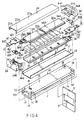
- Figure 1 is an exploded view showing all elements in construction of the present invention;
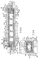
- Figure 2 is a longitudinal sectional drawing of the present invention;
- Figure 3 is a cross sectional drawing of the present invention as viewed from 3 - 3 direction of Figure ;
- Figure 4 shows another preferred embodiment of the present invention;
- Figure 5 is a longitudinal sectional drawing of the present invention as shown in Figure 4; and
- Figure 6 is a cross sectional drawing of the present invention as viewed from 6 - 6 direction of Figure 5.
- As shown in Figures 1 - 3, the present invention comprises: a longitudinal thermal and electrical
conductive casing 1, an electricalinsulating plate 2, an electricalconductive plate 3, a plurality of positive-temperature-coefficient (PTC)semiconductor heating elements 4 made of ceramic semiconductor materials, afirst pole connector 5 electrically connectable to a first pole of a power source, asecond pole connector 6 electrically connectable to a second pole of the power source, and a plurality of heat-exchange plates orfins 7 juxtapositionally embedded on thecasing 1. - The longitudinal thermally and electrically
conductive casing 1 defines a generally rectangular cross-sectionhollow column 10 having an upperlongitudinal plate 12 horizontally forming the upper portion of thecasing 1, a lowerlongitudinal plate 13 horizontally forming the lower portion of thecasing 2 parallel to the upperlongitudinal plate 12, afirst side plate 14 and asecond side plate 15 respectively vertically formed on two opposite sides of thecasing 1, eachside plate longitudinal plate 12 and defining a rectangular throughhole 11 formed through thehollow column 10; afirst socket 16 formed in a first end opening of thehollow column 10; asecond socket 17 formed in a second end opening of thehollow column 10 opposite to thefirst socket 16; a plurality ofprotrusions 18 downwardly protruded from two opposite end portions of the upperlongitudinal plate 12 proximate the twosockets limiting stopper 19 formed on one end portion of the upperlongitudinal plate 12. - Each
side plate corrugated groove casing 1 to tightly assemble theheating elements 4, theconductive plate 3, theinsulating plate 2 within thecasing 1. - The shape of the
hollow column 10 may be modified to be a cylindrical column, or any other polygonal shapes, which are not limited in this invention, but is preferably a rectangular column as shown in the figures. - The electrically
insulating plate 2 is made of electrical insulative materials with suitable thermal conductivity, for instance, a silicon rubber or a polycarbonate layer, having a cross section generally U-shaped; and includes: alongitudinal bottom plate 21 horizontally overlain on an inside surface of the lowerlongitudinal plate 13, a first and asecond side extension longitudinal bottom plate 21 to be retained between the upper and the lowerlongitudinal plates - The electrically
conductive plate 3 made of electrical conductive material includes: alongitudinal holding plate 31 horizontally overlain on thebottom plate 21 of the electricallyinsulating plate 2 having a plurality ofpartitioning projections 311 transversely formed and equally spaced on thelongitudinal holding plate 31 for separately positioning each PTCsemiconductor heating element 4 in between two neighbouringprojections 311 as shown in Figure 2; a firstside edge portion 32 and a secondside edge portion 33 protruded upwardly on two opposite sides of thelongitudinal holding plate 31 for transversely confining each heating element within the twoside edge portions engaging end plate 34 protruded outwardly from theholding plate 31 proximate thefirst socket 16 of thecasing 1 having astem hole 341 formed in theengaging end plate 34, anarcuate portion 35 arcuately bent on theend plate 34 and aslot 36 cut in a central portion of thearcuate portion 35 of theend plate 34. - Each PTC
semiconductor heating element 4 includes a lower conductingsurface 41 contacting the electricalconductive plate 3 and an upper conductingsurface 42 contacting the upperlongitudinal plate 12 of thecasing 1 as shown in Figures 2, 3. - The
first pole connector 5 includes: a first connectingplate 51 having a firstcentral hole 511 formed in theplate 51 and having afirst pole pin 52 with apin hole 521 formed in thepin 52 protruded outwardly from the first connectingplate 51 for connecting a first pole of a power source (not shown), afirst terminal plug 54 sealing thefirst socket 16 of thecasing 1, and aspring washer 53 sandwiched between the first connectingplate 51 and thefirst terminal plug 54 for firmly resiliently holding thefirst pole connector 5 in thefirst socket 16 of thecasing 1 for a sound electrical connection between thefirst pole connector 5 and the electricalconductive plate 3. - The
spring washer 53 is formed with abending portion 530 to form a spring and acentral washer hole 531 in thewasher 53. - The
first terminal plug 54 made of electrically insulative materials includes afirst plug extension 541 protruding inwardly to be engageable with thefirst socket 16 of thecasing 1, a firstinner cavity 542 recessed in thefirst plug extension 541 for snugly receiving thearcuate portion 35 of theengaging end plate 34 of the electricalconductive plate 3, afirst stem 543 protruded downwardly from thefirst plug extension 541 for engaging acentral washer hole 531 of thespring washer 53 and acentral hole 511 of the first connectingplate 51 of thefirst pole connector 5 and astem hole 341 formed in theengaging end plate 34 of the electricalconductive plate 3 for combinably securing thefirst terminal plug 54 with the first spring washer and the electricalconductive plate 3, a plurality ofrecesses 544 in theplug extension 541 engagable with theprotrusions 18 formed in the upperlongitudinal plate 12 of thecasing 1, and afirst cap portion 545 secured with thefirst plug extension 541 sealing thefirst socket 16 of thecasing 1. - The
spring washer 53 should be made of materials durable for high temperature without deteriorating its elasticity. - The
second pole connector 6 includes: a second connectingplate 61 having a secondcentral hole 611 formed in theplate 61 and having asecond pole pin 62 with apin hole 621 formed in thepin 62 protruded outwardly from the second connectingplate 61 for connecting a second pole of the power source (not shown), asecond terminal plug 64 sealing thesecond socket 17 of thecasing 1, and aspring washer 63 sandwiched between the second connectingplate 61 of theconnector 6 positioned under theupper plate 12 of thecasing 1 and thesecond terminal plug 64 for firmly resiliently holding thesecond pole connector 6 in thesecond socket 17 of thecasing 1 for a sound electrical connection between thesecond pole connector 6 and the upperlongitudinal plate 12 of thecasing 1. - The
spring washer 63 similar to theaforesaid washer 53 is formed with abending portion 630 to form a spring and acentral washer hole 631 in thewasher 63. - The
second terminal plug 64 made of electrical insulative material includes asecond plug extension 641 protruding inwardly to be engageable with thesecond socket 17 of thecasing 1, a secondinner cavity 642 recessed in thesecond plug extension 641 for forming an air space between thesecond pole connector 6 and the PTCsemiconductor heating element 4, asecond stem 643 protruded upwardly from thesecond plug extension 641 for engaging acentral washer hole 631 of thesecond spring washer 63 and acentral hole 611 of the second connectingplate 61 of thesecond pole connector 6 for combinably securing thesecond terminal plug 64 with thesecond spring washer 63, and asecond cap portion 645 secured with thesecond plug extension 641 sealing thesecond socket 17 of thecasing 1. - The plurality of PTC
semiconductor heating elements 4 are longitudinally disposed on the electricalconductive plate 3 to be separated by theprojections 311, and are embedded into the rectangular throughhole 11 in thehollow column 10 of the longitudinal thermallyconductive casing 1 having the upper conductingsurface 42 of eachPTC heating element 4 contacted with an inside surface of theupper plate 12 of thecasing 1. The electricalinsulating plate 2 is sandwiched between the electricalconductive plate 3 and the lowerlongitudinal plate 13 as shown in Figures 3, 2. By slightly pressing thecasing 1, theheating elements 4, theconductive plate 3 and theinsulating plate 2 can be tightly compressed for ensuring their internal connection. Any deformation caused by the pressing operation will be concentrated at thecorrugated grooves side plate - Each heat-exchange plate or
fin 7 is formed with a generally rectangularcentral slot 71 engageable with a cross section of thecasing 1 so that eachplate 7 is mounted on thecasing 1 as limited by thelimiting stopper 19 formed on theupper plate 12 of thecasing 1. The thermal expansion coefficient of each heat-exchange plate 7 should be smaller than that of saidcasing 1 so that upon a heating of thecasing 1 by theheating elements 4 thecasing 1 will be thermally expanded quicker than theplates 7 to firmly tightly secure theplates 7 on thecasing 1. - By applying a first or positive pole of a power source to the
first pole connector 5 to electrically connect theconductive plate 3 and thelower surfaces 41 of theheating elements 4 and applying a second or negative pole of the power source to thesecond pole connector 6 to electrically connect theupper plate 12 ofcasing 1 and theupper surfaces 42 of theheating elements 4, theheating elements 4 will exert heat as directed by current therethrough, which heat is transferred outwardly through the heat-exchange plates 7 mounted on thecasing 1. - The present invention is superior to a conventional PTC heating device with the following advantages:
- 1. All the
heating elements 4, theconductive plate 3 and theinsulating plate 2 are fully clad in thecasing 1 which is sealed by twoconnectors - 2. The
arcuate portion 35 and theslot 36 of the electricalconductive plate 3 reduces heat conducting area to prevent over-heating of theconnector 5 for prolonging its service life and increasing an electrical safety. - 3. All elements are encased in the
casing 1 for preventing moisture or weather attack on the elements of the present invention. - 4. It is easier for mass production by reducing production cost since the
hollow column 10 can be integrally made such as by extrusion or integral molding process for any desired cutting length. - 5. The heat-exchange plate or
fin 7 has a thermal expansion coefficient smaller than that of thecasing 1 so that theplates 7 can be firmly mounted on thecasing 1 when heated by theheating elements 4 for ensuring a firm fixation of theplates 7 on thecasing 1. - Another preferred embodiment of the present invention is shown in Figures 4 - 6, in which an upper electrically
conductive plate 3a is formed on theupper surface 42 of theheating element 4 for electrically connecting thesecond pole connector 6 and is packed by an upper insulating plate 2a sandwiched between the upperconductive plate 3a and theupper plate 12 ofcasing 1. Thearcuate portion 35a of the upperconductive plate 3a is formed adjacent to thesecond pole connector 6 for reducing thermal conducting area of the end plate 34a of the upperconductive plate 3a as shown in Figure 5. Thesecond plug extension 641 defines thesecond cavity 642 which snugly receives thearcuate portion 35a of the upperconductive plate 3a. A lowerconductive plate 3 and a lowerinsulating plate 2 are formed on a lower portion inside thecasing 1 for positioning eachheating element 4 in thecasing 1 in cooperation with the upperconductive plate 3a, and the upper insulating plate 2a especially as shown in Figure 6.
Claims (10)
- A PTC semiconductor heating means comprising:
an elongated thermally and electrically conductive casing (1) made as a hollow column (10) having upper, lower and side portions (12, 13, 14, 15), a first socket (16) formed in a first end portion of said casing (1), a second socket (17) formed in a second end portion of said casing (1) opposite to said first socket (16), and at least a corrugated groove (141 or 151) longitudinally recessed in a side portion (14 or 15) of said casing (1);
an electrically insulating plate (2) overlain on a lower portion of said casing (1) within said casing (1);
an electrical conductive plate (3) overlain on said electrical insulating plate (2);
a plurality of positive-temperature-coefficient semiconductor heating elements (4) positioned in said casing (1), each said semiconductor heating element (4) having a lower conducting surface (41) contacting said electrical conducting plate (3) and having an upper conducting surface (42) contacting an upper portion of said casing (1);
a first pole connector (5) connected with a first pole of a power source sealing said first socket (16) of said casing (1) and electrically connected to said electrically conductive plate (3);
a second pole connector (6) connectable with a second pole of the power source sealing said second socket (17) of said casing (1) and electrically connected to the upper portion of said casing (1); and
a plurality of heat-exchange plates (7) longitudinally juxtapositionally mounted on said casing (1), thereby forming a PTC semiconductor heating means with all of said heating elements (1), said conductive plate (3) and said insulating plate (2) fully clad in said casing (1) which is sealed by said first and second pole connector (5, 6) and whereby upon a powering of said first and second pole connectors (5, 6), each said semiconductor heating element (4) is powered to produce heat which is transferred outwardly through said casing (1) and said heat-exchange plates (7). - A PTC semiconductor heating means according to Claim 1, wherein said hollow column of said casing (1) is generally rectangular shaped defining an upper longitudinal plate (12), a lower longitudinal plate (13) parallel to said upper longitudinal plate (12), two side plates (14, 15) respectively vertically secured betweeen said two longitudinal plates (12, 13) and formed on two opposite sides of said two longitudinal plates (12, 13), having a rectangular through hole (11) formed longitudinally through said casing (1), a plurality of protrusions (18) downwardly extended from the two end portions of the upper longitudinal plate (12) for contacting said first pole and second pole connectors (5, 6), and a limiting stopper (19) formed on one end portion of said upper longitudinal plate (12) for limiting said heat-exchange plate (7) mounted on said casing (1).
- A heating means according to Claim 2, wherein said electrically insulating plate (2) has a generally U-shaped cross section and includes: a longitudinal bottom plate (21) horizontally overlain on an inside surface of the lower longitudinal plate (13), a first and a second side extension (22, 23) longitudinally protruded upwardly from two opposite sides of the longitudinal bottom plate (21) to be retained between the upper and the lower longitudinal plates (12, 13) of said casing (1).
- A heating according to Claim 3, wherein said electrically conductive plate (3) includes: a longitudinal holding plate (31) horizontally overlain on a bottom plate (21) of said electrically insulating plate (2) and having a plurality of partitioning projections (311) transversely formed and equally spaced along the length of longitudinal holding plate (31) for separately positioning each said semiconductor heating element (4) in between two neighbouring projections (311)on said longitudinal holding plate (31); a first side edge portion (32) and a second side edge portion (33) protruded upwardly on two opposite sides of the longitudinal holding plate (31) for transversely confining each said heating element (4) within the two side edge portions (32, 33); and an engaging end plate (34) protruded outwardly from the holding plate (31) proximate the first socket (16) of the casing (1) having a stem hole (341) formed in the engaging end plate (34) to be engageable with a first stem (543) formed in said first pole connector (5), an arcuate portion (35) arcuately bent on the end plate (34) and a slot (36) cut in a central portion of the arcuate portion (35) of the end plate (34),
- A heating means according to Claim 1, wherein said first pole connector (5) includes: a first connecting plate (51) having a first pole pin (52) protruded outwardly of said casing first end portion from the first connecting plate (51) for connecting a first pole of a power source, a first terminal plug (54) sealing the first socket (16) of the casing (1), and a first spring washer (53) sandwiched between the first connecting plate (51) and the first terminal plug (54) for firmly resiliently holding the first connecting plate (51) in the first socket (16) of the casing (1) for a sound electrical connection between the first pole connector (5) and the electrical conductive plate (3).
- A heating means according to Claim 5, wherein said first terminal plug (54) made of electrically insulative material includes a first plug extension (541) protruding inwardly to be engageable with the first socket (16) of the casing (1). a first inner cavity (542) recessed in the first plug extension (541) for snugly receiving an arcuate portion (35) of the engaging end plate (34) of the electrical conductive plate (3), a first stem (543) protruded downwardly from the first plug extension (541) for engaging a central washer hole (531) of the first spring washer (53) and a central hole (511) of the first connecting plate (51) of the first pole connector (5) and a stem hole (341) formed in an engaging end plate (34) of the electrical conductive plate (3) for combinably securing the first terminal plug (54) with the first spring washer (53( and the electrical conductive plate (3), a plurality of recesses (544) in the plug extension (541) engageable with a plurality of protrusions (18) formed in an upper longitudinal plate (12) of the casing (1), and a first cap portion (545) integral with the first plug extension (541) sealing the first socket (16) of the casing (1).
- A heating means according to Claim 1, wherein said second pole connector (6) includes: a second connecting plate (61) having a second pole pin (62) protruded outwardly of said casing (1) from the second connecting plate (61) for connecting a second pole of the power source, a second terminal plug (64) sealing the second socket (17) of the casing (1), and a second spring washer (63) sandwiched between the second connecting plate (61) and the second terminal plug (64) for firmly resiliently holding the second connecting plate (61) in the second socket (17) of the casing (1) for a sound electrical connection between the second connecting plate (61) and the upper longitudinal plate (12) of the casing (1).
- A heating means according to Claim 7, wherein said second terminal plug (64) made of electrical insulative material includes a second plug extension (641) protruding inwardly in engagement with the second socket (17) of the casing (1), a second inner cavity (642) recessed in the second plug extension (641) forming an air space between the second pole connector (6) and the adjacent semiconductor heating element (4), a second stem (643) protruded upwardly from the second plug extension (641) engaging a central washer hole (631) of the second spring washer (63) and a central hole (611) of the second connecting plate (61) of the second pole connector (6) and combinably securing the second terminal plug (64) with the second spring washer (63) and second connecting plate (61), and a second cap portion (645) integral with the second plug extension (641) sealing the second socket (17) of the casing (1).
- A heating means according to Claim 1, wherein each said heat-exchange plate (7) is formed with a central slot (71) engageable with a cross section of the casing (1) so that each said plate (7) is mounted on the casing (1) as limited by a limiting stopper (19) formed on the casing (1), the thermal expansion coefficient of each said heat-exchange plate (7) being smaller than that of said casing (1) so that upon a heating of the casing (1) by the heating elements (4) the casing (1) will be thermally expanded more quickly than the heat-exchange plates (7) to firmly tightly secure the heat-exchange plates (7) on the casing (1).
- A PTC semiconductor heating means comprising:
an elongated thermally and electrically conductive casing (1) made as a hollow column (10) having a first socket (16) formed in a first end portion of said casing (1), and a second socket (17) formed in a second end portion of said casing (1) opposite to said first socket (16);
an upper and a lower electrical insulating plate (2a, 2) respectively formed in said casing (1), on an upper portion and a lower portion of said casing (1);
an upper and a lower electrically conductive plate (3a, 3) respectively retained on said two electrical insulating plates (2a, 2);
a plurality of positive-temperature-coefficient semiconductor heating elements (4) positioned in said casing (1) and retained between laid two electrical conductive plates (3a, 3), each said semiconductor heating element (4) having a lower electrical conducting surface (41) contacting said lower electrical conductive plate (3) and having an upper conducting surface (42) contacting the upper electrical conductive plate (3a);
a first pole connector (5) connectable to a first pole of a power source sealing said first socket (16) of said casing (1) and electrically connected to said lower electrical conducting plate (3);
a second pole connector (6) connectable to a second pole of the power source sealing said second socket (17) of said casing (1) and electrically connected to said upper electrical conductive plate (3a); and
a plurality of heat-exchange plates (7) longitudinally juxtapositionally mounted on said casing (1), whereby upon a powering of said first and second pole connectors (5, 6), each said semiconductor heating element (4) is powered to produce heat transferred outwardly through said casing (1) and said heat-exchange plates.
Applications Claiming Priority (2)
| Application Number | Priority Date | Filing Date | Title |
|---|---|---|---|
| US07/706,170 US5198640A (en) | 1991-05-28 | 1991-05-28 | Fully clad electric ptc heater with a finned protective casing |
| US706170 | 1991-05-28 |
Publications (3)
| Publication Number | Publication Date |
|---|---|
| EP0516112A2 true EP0516112A2 (en) | 1992-12-02 |
| EP0516112A3 EP0516112A3 (en) | 1993-06-02 |
| EP0516112B1 EP0516112B1 (en) | 1995-04-19 |
Family
ID=24836491
Family Applications (1)
| Application Number | Title | Priority Date | Filing Date |
|---|---|---|---|
| EP92109005A Expired - Lifetime EP0516112B1 (en) | 1991-05-28 | 1992-05-27 | PTC semiconductor heating means having fully clad casing |
Country Status (4)
| Country | Link |
|---|---|
| US (1) | US5198640A (en) |
| EP (1) | EP0516112B1 (en) |
| DE (1) | DE69202099T2 (en) |
| GB (1) | GB2256352B (en) |
Cited By (12)
| Publication number | Priority date | Publication date | Assignee | Title |
|---|---|---|---|---|
| EP1059945A1 (en) * | 1997-12-31 | 2000-12-20 | A.T.C.T. Advanced Thermal Chips Technologies Ltd. | Autoclave device and ptc heating arrangement for use therewith |
| FR2826829A1 (en) * | 2001-06-27 | 2003-01-03 | Valeo Climatisation | Heat exchanger for motor vehicle air conditioning has tubes containing electrical resistances spaced by separators |
| EP1318694A1 (en) | 2001-12-06 | 2003-06-11 | Catem GmbH & Co.KG | Electrical heating device |
| EP1580495A1 (en) * | 2004-03-22 | 2005-09-28 | Halla Climate Control Corporation | Electric heater |
| EP1691999A1 (en) * | 2003-11-18 | 2006-08-23 | Woory Industrial Company Ltd. | Ptc element module and pre-heater for vehicles including the same |
| EP0707434B2 (en) † | 1994-10-14 | 2009-05-06 | Behr GmbH & Co. KG | Radiator for motor vehicle heating system |
| EP2236330A1 (en) * | 2009-03-30 | 2010-10-06 | Eberspächer catem GmbH & Co. KG | Electric heater for a motor vehicle |
| EP2346304B1 (en) | 2010-01-15 | 2016-06-15 | MAHLE Behr GmbH & Co. KG | Heat exchanger |
| CN108257748A (en) * | 2018-02-06 | 2018-07-06 | 东莞市晴远电子有限公司 | A kind of novel patch resistance |
| DE19922668B4 (en) * | 1999-05-18 | 2020-03-05 | Mahle International Gmbh | Radiators for automobiles |
| EP3637951A1 (en) * | 2018-10-10 | 2020-04-15 | STEGO-Holding GmbH | Tempering device and system |
| USD896360S1 (en) | 2018-08-20 | 2020-09-15 | Stego-Holding Gmbh | Convector |
Families Citing this family (38)
| Publication number | Priority date | Publication date | Assignee | Title |
|---|---|---|---|---|
| US5326418A (en) * | 1992-04-14 | 1994-07-05 | Yeh Yuan Chang | Method of making positive-temperature-coefficient thermistor heating element |
| US5377298A (en) * | 1993-04-21 | 1994-12-27 | Yang; Chiung-Hsiang | Cassette PTC semiconductor heating apparatus |
| DE4435881C2 (en) * | 1994-10-07 | 1997-01-30 | Michael Roser | heating system |
| IL121448A (en) * | 1997-08-01 | 2001-04-30 | A T C T Advanced Thermal Chips | Electrical ptc heating device |
| DE29719639U1 (en) * | 1997-11-05 | 1998-12-03 | Eichenauer Gmbh & Co Kg F | Device for heating interiors, in particular motor vehicles |
| ES2236991T3 (en) * | 1999-06-15 | 2005-07-16 | DAVID & BAADER DBK SPEZIALFABRIK ELEKTRISCHER APPARATE UND HEIZWIDERSTANDE GMBH | HEATING DEVICE INTENDED FOR AIR HEATING. |
| US6180930B1 (en) * | 1999-12-29 | 2001-01-30 | Chia-Hsiung Wu | Heater with enclosing envelope |
| WO2002017681A2 (en) | 2000-08-22 | 2002-02-28 | A.T.C.T Advanced Thermal Chips Technologies Ltd. | Liquid heating method and apparatus particularly useful for vaporizing a liquid condensate from cooling devices |
| US6442341B1 (en) * | 2000-11-27 | 2002-08-27 | Chia-Hsiung Wu | Simple-type fluid heating tube structural arrangement |
| DE20121116U1 (en) * | 2001-12-21 | 2003-04-24 | Eichenauer Gmbh & Co Kg F | Electric heating device for heating a liquid in a motor vehicle |
| EP1327834B1 (en) * | 2002-01-15 | 2004-10-27 | David + Baader DBK Spezialfabrik Elektrischer Apparate und Heizwiderstände GmbH | Radiating element for a heating apparatus |
| EP1467599B1 (en) * | 2003-04-12 | 2008-11-26 | Eichenauer Heizelemente GmbH & Co.KG | Device for the admission of ceramic heating elements and procedure for the production of such |
| DE102004021979A1 (en) * | 2004-05-04 | 2005-11-24 | Eichenauer Heizelemente Gmbh & Co. Kg | Method for electrically insulating an electrical functional element and device having such insulated functional elements |
| KR100609452B1 (en) * | 2005-05-20 | 2006-08-03 | 모딘코리아 유한회사 | Ptc rod assembly and pre-heater including the same |
| JP2007024491A (en) * | 2005-07-15 | 2007-02-01 | Modine Korea Llc | Pct rod assembly, and preheater for vehicle equipped therewith |
| US7230215B2 (en) * | 2005-08-26 | 2007-06-12 | Cheng Ping Lin | Heat generating device formed of heat generating diaphragm plates |
| ES2303712T3 (en) | 2005-09-23 | 2008-08-16 | CATEM GMBH & CO. KG | HEAT GENERATING ELEMENT FOR A HEATING DEVICE. |
| EP2127924B1 (en) * | 2006-06-28 | 2011-01-05 | Eberspächer catem GmbH & Co. KG | Electrical heating device |
| AT504216B1 (en) * | 2006-12-18 | 2008-04-15 | Zorn Heinz | Element for producing electrically heatable covering with connecting elements, is connected to multilayer printed circuit board, whose electrically conductive surface facing element are connected to electrical contact |
| ES2382138T3 (en) * | 2007-07-18 | 2012-06-05 | Eberspächer Catem Gmbh & Co. Kg | Electric heating device |
| EP2017548B1 (en) * | 2007-07-20 | 2010-10-13 | Eberspächer catem GmbH & Co. KG | Electric heating device, in particular for motor vehicles |
| CA2787877C (en) * | 2009-02-24 | 2015-01-13 | Sharp Kabushiki Kaisha | An air conditioner with a removable heater unit and a heat exchanger |
| US20110127247A1 (en) * | 2009-12-02 | 2011-06-02 | Hyundai Motor Company | Pre-heater apparatus for vehicle |
| US8698051B2 (en) * | 2011-07-14 | 2014-04-15 | Amphenol Thermometrics, Inc. | Heating system, heater, and methods of heating a component |
| DE102011054750B4 (en) | 2011-10-24 | 2014-08-21 | Stego-Holding Gmbh | Cooling and holding body for heating elements, heater and method for producing a cooling and holding body |
| DE102011054752B4 (en) * | 2011-10-24 | 2014-09-04 | Stego-Holding Gmbh | Cooling and holding body for heating elements, heater and method for producing a cooling and holding body |
| KR101313895B1 (en) * | 2011-11-01 | 2013-10-01 | 동아하이테크 주식회사 | Heat Rod Structure of Pre-Heater for Vehicle |
| DE102011056930A1 (en) * | 2011-12-22 | 2013-06-27 | Borgwarner Beru Systems Gmbh | Electric heater |
| DE102012109801B4 (en) * | 2012-10-15 | 2015-02-05 | Borgwarner Ludwigsburg Gmbh | Electric heater |
| US20140124499A1 (en) * | 2012-11-05 | 2014-05-08 | Betacera Inc. | Electric heating apparatus with waterproof mechanism |
| CN103945574B (en) * | 2014-03-25 | 2015-11-25 | 常熟市林芝电热器件有限公司 | The film strip of PTC heat generating core automatic assembling machine and electrode slice transfer device structure |
| CN105072710B (en) * | 2015-08-24 | 2017-03-22 | 江苏源之翼电气有限公司 | Stacked high-power PTC heater |
| KR101762094B1 (en) * | 2017-04-04 | 2017-07-26 | 김이태 | Power connector only for heat film |
| DE102017120467A1 (en) * | 2017-09-06 | 2019-03-07 | Dbk David + Baader Gmbh | Heaters and process for its manufacture and heating registers |
| DE102018101453A1 (en) * | 2018-01-23 | 2019-07-25 | Borgwarner Ludwigsburg Gmbh | Heating device and method for producing a heating rod |
| DE102019108435A1 (en) * | 2019-04-01 | 2020-10-15 | Borgwarner Ludwigsburg Gmbh | Heater with peeled-off fins and method of making a heating rod |
| CN110454969B (en) * | 2019-08-02 | 2023-05-30 | 乔路铭科技股份有限公司 | PTC electric heater |
| GB2613777A (en) * | 2021-12-03 | 2023-06-21 | Amphenol Thermometrics Inc | Heating unit |
Citations (4)
| Publication number | Priority date | Publication date | Assignee | Title |
|---|---|---|---|---|
| US3742422A (en) * | 1971-11-22 | 1973-06-26 | Cts Corp | High voltage resistor |
| US4037082A (en) * | 1976-04-30 | 1977-07-19 | Murata Manufacturing Co., Ltd. | Positive temperature coefficient semiconductor heating device |
| EP0240447A2 (en) * | 1986-04-04 | 1987-10-07 | Emerson Electric Co. | PTC thermal protector |
| JPH01262601A (en) * | 1988-04-14 | 1989-10-19 | Murata Mfg Co Ltd | Thermistor device |
Family Cites Families (4)
| Publication number | Priority date | Publication date | Assignee | Title |
|---|---|---|---|---|
| DE3042420A1 (en) * | 1980-11-11 | 1982-06-24 | Fritz Eichenauer GmbH & Co KG, 6744 Kandel | Electric heater with flat heating elements - has sheet metal contact strips, with resilient fastening tags, as heater terminals |
| EP0262243B1 (en) * | 1986-10-01 | 1991-02-20 | David & Baader DBK Spezialfabrik elektrischer Apparate und Heizwiderstände GmbH | Ptc-heating resistor |
| JPH0734390B2 (en) * | 1987-09-11 | 1995-04-12 | 株式会社村田製作所 | PTC thermistor device |
| DE3902205A1 (en) * | 1989-01-26 | 1990-08-02 | Eichenauer Gmbh & Co Kg F | HOLDING PART FOR PTC ELEMENTS |
-
1991
- 1991-05-28 US US07/706,170 patent/US5198640A/en not_active Expired - Fee Related
- 1991-05-29 GB GB9111483A patent/GB2256352B/en not_active Expired - Fee Related
-
1992
- 1992-05-27 DE DE69202099T patent/DE69202099T2/en not_active Expired - Fee Related
- 1992-05-27 EP EP92109005A patent/EP0516112B1/en not_active Expired - Lifetime
Patent Citations (4)
| Publication number | Priority date | Publication date | Assignee | Title |
|---|---|---|---|---|
| US3742422A (en) * | 1971-11-22 | 1973-06-26 | Cts Corp | High voltage resistor |
| US4037082A (en) * | 1976-04-30 | 1977-07-19 | Murata Manufacturing Co., Ltd. | Positive temperature coefficient semiconductor heating device |
| EP0240447A2 (en) * | 1986-04-04 | 1987-10-07 | Emerson Electric Co. | PTC thermal protector |
| JPH01262601A (en) * | 1988-04-14 | 1989-10-19 | Murata Mfg Co Ltd | Thermistor device |
Non-Patent Citations (1)
| Title |
|---|
| PATENT ABSTRACTS OF JAPAN vol. 14, no. 22 (E-874)17 January 1990 & JP-A-01 262 601 ( MURATA MFG ) * |
Cited By (21)
| Publication number | Priority date | Publication date | Assignee | Title |
|---|---|---|---|---|
| EP0707434B2 (en) † | 1994-10-14 | 2009-05-06 | Behr GmbH & Co. KG | Radiator for motor vehicle heating system |
| EP1059945A4 (en) * | 1997-12-31 | 2003-04-23 | A T C T Advanced Thermal Chips | Autoclave device and ptc heating arrangement for use therewith |
| EP1059945A1 (en) * | 1997-12-31 | 2000-12-20 | A.T.C.T. Advanced Thermal Chips Technologies Ltd. | Autoclave device and ptc heating arrangement for use therewith |
| DE19922668B4 (en) * | 1999-05-18 | 2020-03-05 | Mahle International Gmbh | Radiators for automobiles |
| FR2826829A1 (en) * | 2001-06-27 | 2003-01-03 | Valeo Climatisation | Heat exchanger for motor vehicle air conditioning has tubes containing electrical resistances spaced by separators |
| EP1318694A1 (en) | 2001-12-06 | 2003-06-11 | Catem GmbH & Co.KG | Electrical heating device |
| US6720536B2 (en) | 2001-12-06 | 2004-04-13 | Catem Gmbh & Co., Kg | Electric heating device |
| EP1988749A1 (en) * | 2001-12-06 | 2008-11-05 | Catem GmbH & Co.KG | Electric heating device |
| EP1691999A1 (en) * | 2003-11-18 | 2006-08-23 | Woory Industrial Company Ltd. | Ptc element module and pre-heater for vehicles including the same |
| EP1691999A4 (en) * | 2003-11-18 | 2014-03-05 | Woory Ind Co Ltd | Ptc element module and pre-heater for vehicles including the same |
| EP1580495A1 (en) * | 2004-03-22 | 2005-09-28 | Halla Climate Control Corporation | Electric heater |
| CN100402941C (en) * | 2004-03-22 | 2008-07-16 | 汉拏空调株式会社 | Electric heater |
| US7064301B2 (en) | 2004-03-22 | 2006-06-20 | Halla Climate Control Corporation | Electric heater |
| EP2236330A1 (en) * | 2009-03-30 | 2010-10-06 | Eberspächer catem GmbH & Co. KG | Electric heater for a motor vehicle |
| CN101854748A (en) * | 2009-03-30 | 2010-10-06 | 埃贝赫卡腾有限两合公司 | The electric heater unit that is used for motor vehicle |
| CN101854748B (en) * | 2009-03-30 | 2013-01-02 | 埃贝赫卡腾有限两合公司 | Electric heater for a motor vehicle |
| EP2346304B1 (en) | 2010-01-15 | 2016-06-15 | MAHLE Behr GmbH & Co. KG | Heat exchanger |
| CN108257748A (en) * | 2018-02-06 | 2018-07-06 | 东莞市晴远电子有限公司 | A kind of novel patch resistance |
| USD896360S1 (en) | 2018-08-20 | 2020-09-15 | Stego-Holding Gmbh | Convector |
| EP3637951A1 (en) * | 2018-10-10 | 2020-04-15 | STEGO-Holding GmbH | Tempering device and system |
| US11487306B2 (en) | 2018-10-10 | 2022-11-01 | Stego-Holding Gmbh | Temperature control device and system |
Also Published As
| Publication number | Publication date |
|---|---|
| US5198640A (en) | 1993-03-30 |
| EP0516112B1 (en) | 1995-04-19 |
| DE69202099D1 (en) | 1995-05-24 |
| GB2256352B (en) | 1994-11-09 |
| EP0516112A3 (en) | 1993-06-02 |
| GB9111483D0 (en) | 1991-07-17 |
| GB2256352A (en) | 1992-12-02 |
| DE69202099T2 (en) | 1995-12-21 |
Similar Documents
| Publication | Publication Date | Title |
|---|---|---|
| EP0516112B1 (en) | PTC semiconductor heating means having fully clad casing | |
| US6180930B1 (en) | Heater with enclosing envelope | |
| US5377298A (en) | Cassette PTC semiconductor heating apparatus | |
| US5854471A (en) | Apparatus using a thermistor with a positive temperature coefficient | |
| US5294852A (en) | Thermally protected electric motor | |
| US3996493A (en) | Fluorescent lamp unit having ballast resistor | |
| JPH0734390B2 (en) | PTC thermistor device | |
| JPS60112281A (en) | Heater | |
| US5658479A (en) | Positive temperature coefficient thermistor heater and positive temperature coefficient thermistor heater device using the same | |
| JPH022802U (en) | ||
| US5282758A (en) | Electrical contact | |
| KR100519993B1 (en) | PTC Air-Heater | |
| US4311900A (en) | Heater band | |
| US4204316A (en) | Method of manufacture of a heater band | |
| JPH0734392B2 (en) | PTC thermistor heating device | |
| JPH051195U (en) | Electric heating device | |
| JPH08138836A (en) | Rod ptc heater | |
| JP2001351764A (en) | Positive characteristic ceramic heating element unit | |
| KR200214981Y1 (en) | The thermistor heater | |
| KR100266983B1 (en) | Seramic heating device | |
| JP3066135U (en) | Heater using positive characteristic thermistor element | |
| JPH0718155Y2 (en) | PTC thermistor device | |
| JP3988749B2 (en) | Electric heater | |
| JP2998883B2 (en) | Connection terminal and connection circuit for heating element | |
| JP4090549B2 (en) | Positive temperature coefficient thermistor device |
Legal Events
| Date | Code | Title | Description |
|---|---|---|---|
| PUAI | Public reference made under article 153(3) epc to a published international application that has entered the european phase |
Free format text: ORIGINAL CODE: 0009012 |
|
| AK | Designated contracting states |
Kind code of ref document: A2 Designated state(s): DE FR IT NL |
|
| PUAL | Search report despatched |
Free format text: ORIGINAL CODE: 0009013 |
|
| AK | Designated contracting states |
Kind code of ref document: A3 Designated state(s): DE FR IT NL |
|
| 17P | Request for examination filed |
Effective date: 19930916 |
|
| 17Q | First examination report despatched |
Effective date: 19940628 |
|
| GRAA | (expected) grant |
Free format text: ORIGINAL CODE: 0009210 |
|
| AK | Designated contracting states |
Kind code of ref document: B1 Designated state(s): DE FR IT NL |
|
| PG25 | Lapsed in a contracting state [announced via postgrant information from national office to epo] |
Ref country code: IT Free format text: LAPSE BECAUSE OF FAILURE TO SUBMIT A TRANSLATION OF THE DESCRIPTION OR TO PAY THE FEE WITHIN THE PRE;WARNING: LAPSES OF ITALIAN PATENTS WITH EFFECTIVE DATE BEFORE 2007 MAY HAVE OCCURRED AT ANY TIME BEFORE 2007. THE CORRECT EFFECTIVE DATE MAY BE DIFFERENT FROM THE ONE RECORDED.SCRIBED TIME-LIMIT Effective date: 19950419 Ref country code: NL Free format text: LAPSE BECAUSE OF FAILURE TO SUBMIT A TRANSLATION OF THE DESCRIPTION OR TO PAY THE FEE WITHIN THE PRESCRIBED TIME-LIMIT Effective date: 19950419 |
|
| REF | Corresponds to: |
Ref document number: 69202099 Country of ref document: DE Date of ref document: 19950524 |
|
| ET | Fr: translation filed | ||
| NLV1 | Nl: lapsed or annulled due to failure to fulfill the requirements of art. 29p and 29m of the patents act | ||
| PLBE | No opposition filed within time limit |
Free format text: ORIGINAL CODE: 0009261 |
|
| STAA | Information on the status of an ep patent application or granted ep patent |
Free format text: STATUS: NO OPPOSITION FILED WITHIN TIME LIMIT |
|
| 26N | No opposition filed | ||
| PGFP | Annual fee paid to national office [announced via postgrant information from national office to epo] |
Ref country code: FR Payment date: 19960529 Year of fee payment: 5 |
|
| PGFP | Annual fee paid to national office [announced via postgrant information from national office to epo] |
Ref country code: DE Payment date: 19970521 Year of fee payment: 6 |
|
| PG25 | Lapsed in a contracting state [announced via postgrant information from national office to epo] |
Ref country code: FR Free format text: LAPSE BECAUSE OF NON-PAYMENT OF DUE FEES Effective date: 19980130 |
|
| REG | Reference to a national code |
Ref country code: FR Ref legal event code: ST |
|
| PG25 | Lapsed in a contracting state [announced via postgrant information from national office to epo] |
Ref country code: DE Free format text: LAPSE BECAUSE OF NON-PAYMENT OF DUE FEES Effective date: 19990302 |