EP0240280B1 - Raccords rapidement démontables et structures comportant les mêmes raccords - Google Patents
Raccords rapidement démontables et structures comportant les mêmes raccords Download PDFInfo
- Publication number
- EP0240280B1 EP0240280B1 EP87302720A EP87302720A EP0240280B1 EP 0240280 B1 EP0240280 B1 EP 0240280B1 EP 87302720 A EP87302720 A EP 87302720A EP 87302720 A EP87302720 A EP 87302720A EP 0240280 B1 EP0240280 B1 EP 0240280B1
- Authority
- EP
- European Patent Office
- Prior art keywords
- ball
- joint
- socket
- elements
- joint means
- Prior art date
- Legal status (The legal status is an assumption and is not a legal conclusion. Google has not performed a legal analysis and makes no representation as to the accuracy of the status listed.)
- Expired - Lifetime
Links
- 230000000295 complement effect Effects 0.000 claims description 7
- 230000006835 compression Effects 0.000 claims description 7
- 238000007906 compression Methods 0.000 claims description 7
- 230000000717 retained effect Effects 0.000 claims description 7
- 238000003780 insertion Methods 0.000 claims description 6
- 230000037431 insertion Effects 0.000 claims description 6
- 238000000465 moulding Methods 0.000 claims description 4
- 230000014759 maintenance of location Effects 0.000 claims description 3
- 239000000463 material Substances 0.000 claims description 3
- 239000004033 plastic Substances 0.000 claims description 3
- 229920003023 plastic Polymers 0.000 claims description 3
- 230000002401 inhibitory effect Effects 0.000 claims 1
- 238000004519 manufacturing process Methods 0.000 description 4
- 241001122767 Theaceae Species 0.000 description 2
- 230000001419 dependent effect Effects 0.000 description 2
- 238000000034 method Methods 0.000 description 2
- 229910001209 Low-carbon steel Inorganic materials 0.000 description 1
- 238000010276 construction Methods 0.000 description 1
- 230000003292 diminished effect Effects 0.000 description 1
- 238000003197 gene knockdown Methods 0.000 description 1
- 235000012054 meals Nutrition 0.000 description 1
- 239000002184 metal Substances 0.000 description 1
- 238000012986 modification Methods 0.000 description 1
- 230000004048 modification Effects 0.000 description 1
- 239000007787 solid Substances 0.000 description 1
- 239000002023 wood Substances 0.000 description 1
Images

Classifications
-
- F—MECHANICAL ENGINEERING; LIGHTING; HEATING; WEAPONS; BLASTING
- F16—ENGINEERING ELEMENTS AND UNITS; GENERAL MEASURES FOR PRODUCING AND MAINTAINING EFFECTIVE FUNCTIONING OF MACHINES OR INSTALLATIONS; THERMAL INSULATION IN GENERAL
- F16B—DEVICES FOR FASTENING OR SECURING CONSTRUCTIONAL ELEMENTS OR MACHINE PARTS TOGETHER, e.g. NAILS, BOLTS, CIRCLIPS, CLAMPS, CLIPS OR WEDGES; JOINTS OR JOINTING
- F16B21/00—Means for preventing relative axial movement of a pin, spigot, shaft or the like and a member surrounding it; Stud-and-socket releasable fastenings
- F16B21/06—Releasable fastening devices with snap-action
-
- A—HUMAN NECESSITIES
- A47—FURNITURE; DOMESTIC ARTICLES OR APPLIANCES; COFFEE MILLS; SPICE MILLS; SUCTION CLEANERS IN GENERAL
- A47B—TABLES; DESKS; OFFICE FURNITURE; CABINETS; DRAWERS; GENERAL DETAILS OF FURNITURE
- A47B87/00—Sectional furniture, i.e. combinations of complete furniture units, e.g. assemblies of furniture units of the same kind such as linkable cabinets, tables, racks or shelf units
- A47B87/02—Sectional furniture, i.e. combinations of complete furniture units, e.g. assemblies of furniture units of the same kind such as linkable cabinets, tables, racks or shelf units stackable ; stackable and linkable
- A47B87/0207—Stackable racks, trays or shelf units
- A47B87/0223—Shelves stackable by means of poles or tubular members as distance-holders therebetween
-
- F—MECHANICAL ENGINEERING; LIGHTING; HEATING; WEAPONS; BLASTING
- F16—ENGINEERING ELEMENTS AND UNITS; GENERAL MEASURES FOR PRODUCING AND MAINTAINING EFFECTIVE FUNCTIONING OF MACHINES OR INSTALLATIONS; THERMAL INSULATION IN GENERAL
- F16B—DEVICES FOR FASTENING OR SECURING CONSTRUCTIONAL ELEMENTS OR MACHINE PARTS TOGETHER, e.g. NAILS, BOLTS, CIRCLIPS, CLAMPS, CLIPS OR WEDGES; JOINTS OR JOINTING
- F16B12/00—Jointing of furniture or the like, e.g. hidden from exterior
- F16B12/10—Jointing of furniture or the like, e.g. hidden from exterior using pegs, bolts, tenons, clamps, clips, or the like
- F16B12/12—Jointing of furniture or the like, e.g. hidden from exterior using pegs, bolts, tenons, clamps, clips, or the like for non-metal furniture parts, e.g. made of wood, of plastics
- F16B12/26—Jointing of furniture or the like, e.g. hidden from exterior using pegs, bolts, tenons, clamps, clips, or the like for non-metal furniture parts, e.g. made of wood, of plastics using snap-action elements
-
- F—MECHANICAL ENGINEERING; LIGHTING; HEATING; WEAPONS; BLASTING
- F16—ENGINEERING ELEMENTS AND UNITS; GENERAL MEASURES FOR PRODUCING AND MAINTAINING EFFECTIVE FUNCTIONING OF MACHINES OR INSTALLATIONS; THERMAL INSULATION IN GENERAL
- F16B—DEVICES FOR FASTENING OR SECURING CONSTRUCTIONAL ELEMENTS OR MACHINE PARTS TOGETHER, e.g. NAILS, BOLTS, CIRCLIPS, CLAMPS, CLIPS OR WEDGES; JOINTS OR JOINTING
- F16B21/00—Means for preventing relative axial movement of a pin, spigot, shaft or the like and a member surrounding it; Stud-and-socket releasable fastenings
- F16B21/10—Means for preventing relative axial movement of a pin, spigot, shaft or the like and a member surrounding it; Stud-and-socket releasable fastenings by separate parts
- F16B21/16—Means for preventing relative axial movement of a pin, spigot, shaft or the like and a member surrounding it; Stud-and-socket releasable fastenings by separate parts with grooves or notches in the pin or shaft
- F16B21/18—Means for preventing relative axial movement of a pin, spigot, shaft or the like and a member surrounding it; Stud-and-socket releasable fastenings by separate parts with grooves or notches in the pin or shaft with circlips or like resilient retaining devices, i.e. resilient in the plane of the ring or the like; Details
-
- F—MECHANICAL ENGINEERING; LIGHTING; HEATING; WEAPONS; BLASTING
- F16—ENGINEERING ELEMENTS AND UNITS; GENERAL MEASURES FOR PRODUCING AND MAINTAINING EFFECTIVE FUNCTIONING OF MACHINES OR INSTALLATIONS; THERMAL INSULATION IN GENERAL
- F16B—DEVICES FOR FASTENING OR SECURING CONSTRUCTIONAL ELEMENTS OR MACHINE PARTS TOGETHER, e.g. NAILS, BOLTS, CIRCLIPS, CLAMPS, CLIPS OR WEDGES; JOINTS OR JOINTING
- F16B7/00—Connections of rods or tubes, e.g. of non-circular section, mutually, including resilient connections
- F16B7/04—Clamping or clipping connections
- F16B7/0406—Clamping or clipping connections for rods or tubes being coaxial
- F16B7/0413—Clamping or clipping connections for rods or tubes being coaxial for tubes using the innerside thereof
-
- F—MECHANICAL ENGINEERING; LIGHTING; HEATING; WEAPONS; BLASTING
- F16—ENGINEERING ELEMENTS AND UNITS; GENERAL MEASURES FOR PRODUCING AND MAINTAINING EFFECTIVE FUNCTIONING OF MACHINES OR INSTALLATIONS; THERMAL INSULATION IN GENERAL
- F16B—DEVICES FOR FASTENING OR SECURING CONSTRUCTIONAL ELEMENTS OR MACHINE PARTS TOGETHER, e.g. NAILS, BOLTS, CIRCLIPS, CLAMPS, CLIPS OR WEDGES; JOINTS OR JOINTING
- F16B7/00—Connections of rods or tubes, e.g. of non-circular section, mutually, including resilient connections
- F16B7/04—Clamping or clipping connections
- F16B7/0433—Clamping or clipping connections for rods or tubes being in parallel relationship
-
- Y—GENERAL TAGGING OF NEW TECHNOLOGICAL DEVELOPMENTS; GENERAL TAGGING OF CROSS-SECTIONAL TECHNOLOGIES SPANNING OVER SEVERAL SECTIONS OF THE IPC; TECHNICAL SUBJECTS COVERED BY FORMER USPC CROSS-REFERENCE ART COLLECTIONS [XRACs] AND DIGESTS
- Y10—TECHNICAL SUBJECTS COVERED BY FORMER USPC
- Y10S—TECHNICAL SUBJECTS COVERED BY FORMER USPC CROSS-REFERENCE ART COLLECTIONS [XRACs] AND DIGESTS
- Y10S403/00—Joints and connections
- Y10S403/11—Furniture type having a snap fit
-
- Y—GENERAL TAGGING OF NEW TECHNOLOGICAL DEVELOPMENTS; GENERAL TAGGING OF CROSS-SECTIONAL TECHNOLOGIES SPANNING OVER SEVERAL SECTIONS OF THE IPC; TECHNICAL SUBJECTS COVERED BY FORMER USPC CROSS-REFERENCE ART COLLECTIONS [XRACs] AND DIGESTS
- Y10—TECHNICAL SUBJECTS COVERED BY FORMER USPC
- Y10T—TECHNICAL SUBJECTS COVERED BY FORMER US CLASSIFICATION
- Y10T403/00—Joints and connections
- Y10T403/32—Articulated members
- Y10T403/32975—Rotatable
- Y10T403/32983—Rod in socket
-
- Y—GENERAL TAGGING OF NEW TECHNOLOGICAL DEVELOPMENTS; GENERAL TAGGING OF CROSS-SECTIONAL TECHNOLOGIES SPANNING OVER SEVERAL SECTIONS OF THE IPC; TECHNICAL SUBJECTS COVERED BY FORMER USPC CROSS-REFERENCE ART COLLECTIONS [XRACs] AND DIGESTS
- Y10—TECHNICAL SUBJECTS COVERED BY FORMER USPC
- Y10T—TECHNICAL SUBJECTS COVERED BY FORMER US CLASSIFICATION
- Y10T403/00—Joints and connections
- Y10T403/55—Member ends joined by inserted section
- Y10T403/559—Fluted or splined section
Definitions
- This invention relates to structural modules having quick release joints and to structures incorporating the same.
- Presently available arrangements for connecting and disconnecting structures such as shelving , scaffolding , and other structures include sleeve joints of various kinds and , of course , various kinds of joints including fasteners such as nuts and bolts .
- Sleeve joints can produce a strong and stable resultant structure but they require fairly accurately dimensioned interfitting parts and this requirement leads to production difficulties and expense. Moreover, in view of the fairly accurate fit required , these joints are somewhat susceptible to variations in performance dependent upon temperature variations. The joints are also not particularly easy or quick to assemble .
- references to structural integrity are intended to mean that the structure concerned has , in its assembled state , a rigid structure which retains its rigidity and integrity up to a predetermined load limit dependent upon the physical constants of the joint or joints employed. Obviously , in the case of a quick release joint which can be released by the application of tension , there is a point at which tension or side loading applied to the structure will cause a loss of structural integrity.
- the structural module disclosed in the Morris specification has no utility other than as part of the item of assembled furniture shown in Fig 1, and in any case disassembly is expressly intended to be difficult.
- An object of the present invention is to provide a structural module which can be readily connected to and disconnected from similar modules, and yet which has distinct utility when used on its own, such utility not being substantially diminished by the quick-attach means employed for connection and disconnection purposes.
- ball and socket type joints which themselves incorporate abutment means to substantially prevent pivotal movement of the joint elements in the assembled condition of same. In this way , structural integrity of two structural units connected by the joint is provided .
- abutment means for this purpose enables the advantages of ball and socket type joints in relation to ease of connection and disconnection to be retained in association with an assembly having structural integrity .
- ball and socket type joint as used in this application and in the claims , it is not intended that the structure so-recited should be limited to the use of a spherical ball and a complementary socket .
- the expression is adopted as a convenient means for referring to joints incorporating a projecting shoulder element and is not to be understood as limited to a strictly spherical ball co-operating with a complementary socket but includes any suitable shoulder element (such as a ball ) which co-operates with any suitable receptor element (such as an aperture ) to permit connection and disconnection in the well known manner.
- the joints have a pleasing and attractive appearance in which the shoulder element may be in the form of a ball , acorn or similar structure so as to be used decoratively .
- the shoulder element is usually provided on the uppermost joint element while the receptor element is usually provided as the lowermost one.
- the shoulder element may be formed integrally with a solid member such as a table leg .
- An advantage of an embodiment of the invention disclosed below is that it enables items such as tables to have a multiple function . Two or more such tables when joined one above the other become bookshelves yet can still be instantly made available for the usual function of tables.
- a tiered tea trolley can be provided which readily splits into individual tables for use during a meal , after which these tables are rapidly built back into a tea trolley for a return journey .
- each joint element More than one shoulder element and corresponding receptor element may be provided on each joint element , depending on the strength and rigidity of the required joint.
- the joints may be made from any suitable material , such as Plastic , metal or wood , and may be moulded, cast or fabricated.
- the first joint element 12 shown in Fig.2 comprises a joint base member 16 which is adapted to be secured to an article to be joined , such as a leg of a table or shelf module .
- the joint base member could be formed integrally from an article to be joined.
- a joint shoulder element 18 is carried on the base member 16 and projects therefrom .
- a waist portion 20 connects the shoulder element 18 to the joint base member 16. In this embodiment the waist portion has insignificant longitudinal extent and amounts simply to a slight narrowing of the dimension of the shoulder element 18 as compared with its widest extent 22 in the region 24 of the shoulder element.
- Shoulder element 18 is formed as an integral moulding with the joint base member 16 .
- the same moulding incorporates a projecting portion 26 of generally rectangular tubular form and carrying spaced ribs 28 for engagement with the inner surface 30 of a structural member 32 such as the frame of a table or shelf unit described below.
- Projecting portion 26 and ribs 28 render the joint element 12 a push-fit into structural member 32 , being held in position by frictional forces.
- the joint element could be bonded or otherwise fixed in position.
- joint element 14 comprises a joint base member 34 adapted to be secured to an article to be joined , such as the projecting leg of a table or shelf assembly .
- a joint receptor element 36 is provided in the form of a circular section opening formed in the base member and adapted to receive and hold the shoulder element 18 .
- Opposite sides of the receptor element 36 constitute spaced retainer members which are spaced and positioned and constructed to permit the shoulder element to be inserted between them by the application of compression to the joint 10 . This causes resilient deformation of the receptor element 36 and/or the shoulder element 18 during such insertion , after which the shoulder element is retained by engagement of the retainer members 37 of the receptor element with the waist portion 20 and/or with the portion 38 of shoulder element 18 adjacent waist portion 20.
- second joint element 14 as shown in Fig. 3 comprises a projecting portion 40 and ribs 42 corresponding to the portion 26 and ribs 28 on first joint element 12 seen in Fig.2 , and performing substantially the same functions.
- the annular inner edge 44 of receptor element 36 serves to engage and seat behind the widest portion of shoulder element 18 so as to hold the joint 10 in its assembled condition .
- the base members 16 and 34 of the joint elements 12 and 14 are , as seen in Figs. 2 and 3 , generally square in profile and each is formed with a flat abutment surface 46,48 respectively. These surfaces are positioned for face-to-face contact , each with the other , in the assembled condition of the joint as shown in Fig. 1 .
- the abutment surfaces 46 and 48 are substantially planar and face generally lengthwise of the axis 50 of insertion of the shoulder element 18 into the receptor element 36 .
- the arrangement of the abutment surfaces relative to the shoulder element and receptor element is such that upon insertion of the shoulder element into the receptor element and retention of same thereby , the abutment surfaces make face-to-face contact with each other , thereby defining the retained position of the shoulder element relative to the receptor element , as shown in Fig. 1 , and preventing pivotal movement of the joint elements 12 and 14 in the retained position , whereby the ball joint provides a joint which is connectable and disconnectable by the application of compression and tension respectively , while providing the joint with structural integrity in the connected condition thereof.
- the joint 10 is extremely simple to assemble . It is fitted into the structures to be joined by mere application of compressive force. The structures can then be joined by simple placement of the shoulder element 18 against the receptor element 36 and applying compression to the assembly . The shoulder element and/or the receptor element deforms slightly elastically to permit the shoulder element to pass into its assembled position shown in Fig. 1 where it is retained by engagement of the retainer members on its portion 38 .
- Disconnection merely requires application of sufficient tension to the joint assembly . Tensile loads below this limit do not disconnect the joint. Moreover, all the time that the joint is in its assembled condition , the two structures 32 and 52 joined thereby have structural integrity and pivotal movement between them is,by virtue of the face-to-face engagement of the flat abutment surfaces 46 and 48 , prevented.
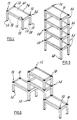
- Module 54 for a stackable table or shelving system .
- Module 54 comprises a rectangular frame 56 having four projecting legs 58 and a flat load-supporting plate 60 mounted on frame 6 , to carry objects on the shelving or table system .
- Module 4 is a fabrication from mild steel or the like and so far as the frame , legs and plate 60 are concerned , is generally of conventional construction .
- joint means is provided to enable module 54 to be assembled with other similar modules as shown in Fig. 5 , to form a stackable table or shelving system , or indeed the stackable table or shelving system shown in Fig. 6 .
- module 54 is provided with four joints 10 for joining to the corresponding joints on adjacent modules .
- each module comprises four joint first elements 12 mounted at the corners of frame 56 and at the lower end of each of the legs 58 there is mounted a second joint element 14 for co-operation with the complementary first joint elements of the adjacent modules.
- the joint element at the bottom of each leg has an aperture or receptor unit 36 and the joint element at the top or frame end of each leg has the projecting shoulder element 18 .
- the modules 54 can be readily stacked in a vertical assembly . This can be achieved very quickly. Likewise , the stack can be readily disconnected by simply pulling the modules apart manually . This enables multiple uses of the equipment to be readily accomplished.
- Fig. 6 shows an alternative stacked arrangement of the modules . It will be appreciated that many other variations are possible.
- the shoulder elements 18 are exposed on the upper portion of the modules. These shoulder elements are relatively small compared with the size of the modules as a whole . Moreover, the shoulder elements are neat and spherical and do not detract from the overall appearance . Indeed , they can be decorated to some extent if necessary.
- the ball and socket type joint provides a simple means of positively holding the joint assembly in its joined condition. Furthermore , the joint permits simple disconnection by mere application of tension . At the same time , the positive holding of the joint in its assembled condition enables the various means for preventing pivotal movement , including abutment surfaces , three or more shoulder and receptor elements , and abutment means on the structures being joined , to act to provide structural integrity in the assembled condition of the structural units.
- abutment surfaces including abutment surfaces , three or more shoulder and receptor elements , and abutment means on the structures being joined
- Consequential advantages arising from these features of the ball and socket type joints include the provision of stackable and unstackable structural units such as tables , shelving , trolleys and the like.
- abutment surface may be provided on each joint element . These surfaces can be at differing angles , each surface being flat or planar.
- the receptor element may be merely a two-sided or three-sided device .
- a prong-like receptor element might well be suitable for certain applications.
- shoulder elements can vary in design considerably so long as they are readily insertable and removable in the manner described above .
- the basic requirement is for a shoulder wider than the waist and tapers leading to the shoulder from both sides.
Landscapes
- Engineering & Computer Science (AREA)
- General Engineering & Computer Science (AREA)
- Mechanical Engineering (AREA)
- Pivots And Pivotal Connections (AREA)
- Combinations Of Printed Boards (AREA)
- Mutual Connection Of Rods And Tubes (AREA)
- Assembled Shelves (AREA)
Claims (3)
- Module structurel (54) prévu pour être connecté à un module complémentaire (54) en relation directe de superposition et d'empilage pour former une structure assemblée structurellement solidaire, ledit module comprenant au moins trois pieds (58) dont chacun comporte une partie de raccord à rotule (12) et une partie de raccord à emboîtement (14), ladite partie de raccord à rotule (12) comportant un premier élément de base (16) et un élément mâle ou de rotule (18) tenu sur ledit premier élément de base, et ladite partie de raccord à emboîtement comportant un deuxième élément de base (34) présentant un orifice (36) qui définit un élément femelle ou d'emboitement prévu pour recevoir et retenir un élément de rotule tel que celui de ladite partie de raccord à rotule (12), ledit élément d'emboîtement étant dimensionné et formé pour recevoir un élément de rotule tel que celui de ladite partie de raccord à rotule et pour permettre l'insertion d'un tel élément de rotule dans ledit élément d'emboîtement par application d'une compression entre ces éléments de raccord de façon à provoquer une déformation élastique d'au moins un desdits éléments de raccord pendant ladite insertion suivie par la rétention de l'élément de rotule, et ledit élément d'emboîtement permettant également l'enlèvement subséquent d'un tel élément de rotule par application d'une traction entre les éléments de raccord, lesdits premier et deuxième éléments de base (16,34) présentant chacun une surface de butée (46,48), chacune de ces surfaces de butée étant placée pour un contact face à face avec la surface de butée d'une partie de raccord complémentaire située sur un module complémentaire lorsque celuici fait partie d'un assemblage, lesdites surfaces de butée étant toutes sensiblement planes et regardant sensiblement dans la direction de l'axe d'insertion d'un élément de rotule dans un élément d'emboîtement, la disposition desdites surfaces de butée étant telle que, lors de l'insertion d'un élément de rotule (18) dans un élément d'emboîtement (36) et de la rétention de l'élément de rotule ainsi produite, les surfaces de butée associées (46,48) viennent en contact mutuel face à face, définissant ainsi la position de retenue de l'élément de rotule par rapport à l'élément d'emboîtement et empêchant le pivotement des éléments concernés dans la dite position de retenue,
caractérisé en ce que(a) la structure desdites parties de raccord à rotule (12,14), qui ne sont pas rainurées, est telle que, lorsque lesdites surfaces de butée (46,48) sont en contact face à face, les surfaces intérieures et de dimension effective minimale des éléments d'emboîtement (36), définies par des éléments de retenue (37) ayant des bords intérieurs (44), sont en contact avec les surfaces extérieures des éléments de rotule (18) juste derrière leurs régions (24) où les éléments de rotule ont leurs dimensions effectives maximales (22), de sorte que lesdits éléments de rotule et d'emboîtement peuvent être facilement accouplés et désaccouplés par simple application manuelle de compression et de traction ;(b) ledit module structurel comprend un cadre (56) et est sous la forme d'un module de table (54) prévu pour être facilement accouplé et désaccouplé de modules similaires adjacents (54) par ladite application manuelle de compression et de traction entre les modules, pour l'utilisation interchangeable d'un module seul ou en relation d'empilage avec un ou plusieurs modules complémentaires ;(c) lesdits pieds (58) dudit module de table sont dirigés d'un même côté dudit cadre, chaque pied comportant un élément de rotule (18) apparent et tourné dans une première direction, à une de ses extrémités, et un élément d'emboîtement (36) apparent et tourné dans l'autre direction, à son autre extrémité, pour coopération mutuelle avec la partie de raccord correspondante d'un autre module similaire (54) ;(d) chacune desdites surfaces de butée (46, 48), à chaque extrémité de chaque pied, est également apparente lorsque ledit module est utilisé seul, et la surface de butée (46) située à l'extrémité de chaque pied adjacente audit cadre est ainsi adjacente à la surface de travail (60) dudit module de table ; et(e) ledit élément de rotule(18) de chaque pied est lui-même directement monté et fait saillie directement vers l'extérieur dans une première direction, à une extrémité du pied, par rapport à sa surface de butée associée (46), et ledit élément d'emboîtement (36) pour recevoir et retenir ledit élément de rotule est de même formé directement dans ledit élément de base (34) à l'autre extrémité du pied, sa surface de butée (48) étant tournée dans la direction opposée, sur son côté extérieur. - Module structurel suivant la revendication 1, caractérisé en ce que ladite partie de raccord à rotule (12) et ladite partie de raccord à emboîtement (14) sont sous la forme de pièces moulées en matière plastique prévues pour être emmanchées par poussée dans des parties d'extrémité creuses desdits pieds (58).
- Module structurel suivant la revendication 2, caractérisé en ce que lesdits éléments de rotule sont emmanchés aux extrémités supérieures desdits pieds.
Applications Claiming Priority (2)
| Application Number | Priority Date | Filing Date | Title |
|---|---|---|---|
| GB08607992A GB2188691A (en) | 1986-04-01 | 1986-04-01 | Quick release plug |
| GB8607992 | 1986-04-01 |
Publications (3)
| Publication Number | Publication Date |
|---|---|
| EP0240280A2 EP0240280A2 (fr) | 1987-10-07 |
| EP0240280A3 EP0240280A3 (en) | 1988-01-20 |
| EP0240280B1 true EP0240280B1 (fr) | 1991-09-18 |
Family
ID=10595521
Family Applications (1)
| Application Number | Title | Priority Date | Filing Date |
|---|---|---|---|
| EP87302720A Expired - Lifetime EP0240280B1 (fr) | 1986-04-01 | 1987-03-30 | Raccords rapidement démontables et structures comportant les mêmes raccords |
Country Status (5)
| Country | Link |
|---|---|
| US (1) | US4797021A (fr) |
| EP (1) | EP0240280B1 (fr) |
| DE (1) | DE3773029D1 (fr) |
| ES (1) | ES2025649T3 (fr) |
| GB (1) | GB2188691A (fr) |
Families Citing this family (24)
| Publication number | Priority date | Publication date | Assignee | Title |
|---|---|---|---|---|
| US4775259A (en) * | 1986-11-04 | 1988-10-04 | Benada Aluminum Of Florida, Inc. | Connector arrangement |
| NL8802569A (nl) * | 1988-10-18 | 1990-05-16 | Feralkon Bv | Stapelwagen en voor zo een wagen bestemde tafel. |
| DE9014987U1 (de) * | 1990-10-31 | 1991-01-10 | Häfele KG, 7270 Nagold | Beschlag |
| IT224689Z2 (it) * | 1991-02-25 | 1996-06-27 | Dispositivo per l'accoppiamento amovibile di due elementi. | |
| ES2181739T3 (es) * | 1994-10-20 | 2003-03-01 | Schueco Int Kg | Adaptador. |
| US5658086A (en) * | 1995-11-24 | 1997-08-19 | Brokaw; Paul E. | Furniture connector |
| EP1201937A1 (fr) | 2000-10-31 | 2002-05-02 | Mario Bissegger | Ensemble pour une liaison de forme de deux panneaux horizontaux d'un meuble |
| US6938966B1 (en) * | 2004-03-12 | 2005-09-06 | Kevin Rouwhorst | Cabinet connector |
| US20090199375A1 (en) * | 2006-01-20 | 2009-08-13 | Fred Koelling | Latching system |
| US7540809B2 (en) * | 2006-04-21 | 2009-06-02 | Costain Paul D | Cue stick joint |
| US7601071B2 (en) * | 2006-04-21 | 2009-10-13 | Costain Paul D | Cue stick joint |
| US20090084740A1 (en) * | 2007-09-28 | 2009-04-02 | Ching-Yi Lin | Sectional rack for storage |
| AU2009202773A1 (en) * | 2008-07-17 | 2010-02-04 | King Furniture (Australia) Pty Ltd | An accessory attaching system |
| US8974139B2 (en) * | 2009-04-02 | 2015-03-10 | Gregory M Saul | Connector for furniture and method of frame manufacture and assembly |
| US8757373B2 (en) * | 2009-06-17 | 2014-06-24 | Golf Sales West, Inc. | Modular golf bag kickstand |
| DE102009048410A1 (de) * | 2009-10-06 | 2011-04-07 | Behr Gmbh & Co. Kg | Schnappbare Befestigungseinrichtung |
| US20110176866A1 (en) * | 2010-01-19 | 2011-07-21 | Miserendino Ronald A | Bible stand connection |
| FR2960865B1 (fr) * | 2010-06-04 | 2014-01-10 | Prefac Beton Environnement | Module de rayonnage |
| TWM391894U (en) * | 2010-06-10 | 2010-11-11 | Yi-Qing Guo | Anti-wearing structure for display rack |
| ITMI20112302A1 (it) * | 2011-12-19 | 2013-06-20 | System Holz Spa | Dispositivo di giunzione per componenti di arredo |
| DE102012101563B4 (de) * | 2012-02-27 | 2015-12-03 | Bodo Rengshausen-Fischbach | Verbindungselement für Möbelelemente sowie ein Möbelelement mit mehreren durch derartige Verbindungselemente verbundenen Formkörpern |
| KR101253462B1 (ko) * | 2012-10-22 | 2013-04-10 | 재 욱 한 | 진열대용 수직프레임 및 이를 이용한 다용도 조립식 진열대 |
| US11267058B2 (en) | 2020-01-29 | 2022-03-08 | Robert Bosch Gmbh | Table saw including tip-in table extension |
| US11975825B2 (en) | 2020-11-23 | 2024-05-07 | Textron Innovations Inc. | Spline with expendable spherical alignment head |
Citations (1)
| Publication number | Priority date | Publication date | Assignee | Title |
|---|---|---|---|---|
| US4037978A (en) * | 1974-08-23 | 1977-07-26 | B.C. Investments Ltd. | Resilient swivel connector |
Family Cites Families (22)
| Publication number | Priority date | Publication date | Assignee | Title |
|---|---|---|---|---|
| US2240268A (en) * | 1939-10-27 | 1941-04-29 | Martin T Ruddy | Dowel |
| US2855206A (en) * | 1957-04-02 | 1958-10-07 | Jacobs Mfg Co | Resilient spacer construction for plate assembly |
| NL108066C (fr) * | 1958-10-01 | |||
| GB882948A (en) * | 1958-10-07 | 1961-11-22 | Shallwin Ltd | Improvements in or relating to interconnectable bodies |
| GB886568A (en) * | 1959-11-27 | 1962-01-10 | Metalastik Ltd | Improvements in or relating to stanchions for passenger transport vehicles |
| GB1107759A (en) * | 1965-06-01 | 1968-03-27 | Burrafirm Ltd | Releasable fastening |
| FR1487153A (fr) * | 1966-07-20 | 1967-06-30 | Assemblage de pièces de bois, en particulier pour meubles, par un dispositif en forme de bouton-pression | |
| US3527486A (en) * | 1967-06-27 | 1970-09-08 | Anton Gamp | Dowel-sleeve assembly |
| JPS4821728Y1 (fr) * | 1968-07-31 | 1973-06-25 | ||
| US3490798A (en) * | 1968-09-27 | 1970-01-20 | Rudolf A Spyra | Ball-and-socket coupling |
| DE1922971A1 (de) * | 1969-05-06 | 1970-11-19 | Becher Dr Hans | Vorrichtung zur loesbaren Verbindung von Moebelbauteilen Kennwort: Moebelverbinder |
| BE757594A (fr) * | 1969-10-22 | 1971-04-16 | Textron Inc | Fermeture a declic en matiere plastique moulee, et bande d'elements pour cette fermeture |
| DE6947564U (de) * | 1969-12-09 | 1970-10-01 | Kunststoff Gmbh | Schnappverbindung. |
| DE7000912U (de) * | 1970-01-13 | 1970-06-11 | Imberger Daniel | Druckknopfverbindung. |
| US3810341A (en) * | 1970-06-12 | 1974-05-14 | H Holz | Multipart joining element for butt and corner joints |
| DE2335288A1 (de) * | 1972-07-14 | 1974-01-31 | Claude Dr Rueff | Vorrichtung zur gegenseitigen, loesbaren verbindung zweier koerper aus weichem oder semihartem material |
| FR2233884A5 (en) * | 1973-06-14 | 1975-01-10 | Sib | Concealed peg for assembling bodies face to face - has tapering ends and central groove for edges of body face holes |
| US4012155A (en) * | 1975-05-02 | 1977-03-15 | Morris Max O | Snap lock connector for components such as knock-down furniture components |
| FR2469600A1 (fr) * | 1979-11-16 | 1981-05-22 | Cofreco | Latte a dispositif d'assemblage incorpore, articles obtenus a partir de ladite latte |
| GB2081570A (en) * | 1980-07-19 | 1982-02-24 | Hext James Leonard | Improvements in dental care equipment |
| GB2149288B (en) * | 1983-11-10 | 1987-08-19 | Kiddie Rigg Limited | Beam for attachment of passenger restraint devices |
| US4616953A (en) * | 1985-09-27 | 1986-10-14 | Daniel Gomes | Knock down pivot fastener |
-
1986
- 1986-04-01 GB GB08607992A patent/GB2188691A/en not_active Withdrawn
-
1987
- 1987-03-23 US US07/029,273 patent/US4797021A/en not_active Expired - Lifetime
- 1987-03-30 DE DE8787302720T patent/DE3773029D1/de not_active Expired - Fee Related
- 1987-03-30 ES ES198787302720T patent/ES2025649T3/es not_active Expired - Lifetime
- 1987-03-30 EP EP87302720A patent/EP0240280B1/fr not_active Expired - Lifetime
Patent Citations (1)
| Publication number | Priority date | Publication date | Assignee | Title |
|---|---|---|---|---|
| US4037978A (en) * | 1974-08-23 | 1977-07-26 | B.C. Investments Ltd. | Resilient swivel connector |
Also Published As
| Publication number | Publication date |
|---|---|
| US4797021A (en) | 1989-01-10 |
| DE3773029D1 (de) | 1991-10-24 |
| EP0240280A3 (en) | 1988-01-20 |
| ES2025649T3 (es) | 1992-04-01 |
| GB8607992D0 (en) | 1986-05-08 |
| EP0240280A2 (fr) | 1987-10-07 |
| GB2188691A (en) | 1987-10-07 |
Similar Documents
| Publication | Publication Date | Title |
|---|---|---|
| EP0240280B1 (fr) | Raccords rapidement démontables et structures comportant les mêmes raccords | |
| US6675979B2 (en) | Furniture assembly system | |
| US4372224A (en) | Knockdown furniture construction | |
| US5411153A (en) | Storage rack assembly system | |
| US3490797A (en) | Clip assembly | |
| US7631605B2 (en) | Connection system for furniture | |
| US8974139B2 (en) | Connector for furniture and method of frame manufacture and assembly | |
| EP2464257B1 (fr) | Système de soutien d'étagère ayant un montant de support cylindrique et fournissant une stabilité et une rigidité améliorées | |
| US7404686B2 (en) | Snap fitting for joining component parts of an article of assembly | |
| US5308146A (en) | Combination chair | |
| US5528996A (en) | Table leg support assembly and method | |
| US9874237B1 (en) | Support assembly joint and applications thereof | |
| EP2738320A3 (fr) | Matériau de plancher comprenant des éléments de plancher sous forme de planches joints par des éléments de liaison | |
| US5190172A (en) | Connection assembly and method for a structural rack | |
| CA2020296A1 (fr) | Etagere comportant deux jeux de cones emboitants | |
| EP0891281A1 (fr) | Palette | |
| US4700986A (en) | Collapsible, portable tote-table | |
| US4430947A (en) | Shelf support system | |
| US3480155A (en) | Steel shelving | |
| US20060284469A1 (en) | Furniture connector | |
| US6338592B1 (en) | Article connector | |
| US20050023944A1 (en) | Interlocking component assembly system | |
| JP3001529U (ja) | 組立式什器 | |
| JPS581174Y2 (ja) | 支柱用継手 | |
| JPH0446600Y2 (fr) |
Legal Events
| Date | Code | Title | Description |
|---|---|---|---|
| PUAI | Public reference made under article 153(3) epc to a published international application that has entered the european phase |
Free format text: ORIGINAL CODE: 0009012 |
|
| AK | Designated contracting states |
Kind code of ref document: A2 Designated state(s): DE ES FR GB IT SE |
|
| PUAL | Search report despatched |
Free format text: ORIGINAL CODE: 0009013 |
|
| AK | Designated contracting states |
Kind code of ref document: A3 Designated state(s): DE ES FR GB IT SE |
|
| 17P | Request for examination filed |
Effective date: 19880707 |
|
| 17Q | First examination report despatched |
Effective date: 19880915 |
|
| GRAA | (expected) grant |
Free format text: ORIGINAL CODE: 0009210 |
|
| AK | Designated contracting states |
Kind code of ref document: B1 Designated state(s): DE ES FR GB IT SE |
|
| PG25 | Lapsed in a contracting state [announced via postgrant information from national office to epo] |
Ref country code: SE Effective date: 19910918 |
|
| REF | Corresponds to: |
Ref document number: 3773029 Country of ref document: DE Date of ref document: 19911024 |
|
| ET | Fr: translation filed | ||
| ITF | It: translation for a ep patent filed | ||
| K2C2 | Correction of patent specification (partial reprint) published |
Effective date: 19910918 |
|
| REG | Reference to a national code |
Ref country code: ES Ref legal event code: FG2A Ref document number: 2025649 Country of ref document: ES Kind code of ref document: T3 |
|
| PLBE | No opposition filed within time limit |
Free format text: ORIGINAL CODE: 0009261 |
|
| STAA | Information on the status of an ep patent application or granted ep patent |
Free format text: STATUS: NO OPPOSITION FILED WITHIN TIME LIMIT |
|
| 26N | No opposition filed | ||
| PGFP | Annual fee paid to national office [announced via postgrant information from national office to epo] |
Ref country code: FR Payment date: 19960315 Year of fee payment: 10 |
|
| PGFP | Annual fee paid to national office [announced via postgrant information from national office to epo] |
Ref country code: DE Payment date: 19960328 Year of fee payment: 10 |
|
| PGFP | Annual fee paid to national office [announced via postgrant information from national office to epo] |
Ref country code: ES Payment date: 19960329 Year of fee payment: 10 |
|
| PG25 | Lapsed in a contracting state [announced via postgrant information from national office to epo] |
Ref country code: ES Free format text: LAPSE BECAUSE OF NON-PAYMENT OF DUE FEES Effective date: 19970331 |
|
| PG25 | Lapsed in a contracting state [announced via postgrant information from national office to epo] |
Ref country code: FR Free format text: LAPSE BECAUSE OF NON-PAYMENT OF DUE FEES Effective date: 19971128 |
|
| PG25 | Lapsed in a contracting state [announced via postgrant information from national office to epo] |
Ref country code: DE Effective date: 19971202 |
|
| REG | Reference to a national code |
Ref country code: FR Ref legal event code: ST |
|
| REG | Reference to a national code |
Ref country code: ES Ref legal event code: FD2A Effective date: 19990301 |
|
| REG | Reference to a national code |
Ref country code: GB Ref legal event code: IF02 |
|
| PGFP | Annual fee paid to national office [announced via postgrant information from national office to epo] |
Ref country code: GB Payment date: 20040324 Year of fee payment: 18 |
|
| PG25 | Lapsed in a contracting state [announced via postgrant information from national office to epo] |
Ref country code: IT Free format text: LAPSE BECAUSE OF NON-PAYMENT OF DUE FEES;WARNING: LAPSES OF ITALIAN PATENTS WITH EFFECTIVE DATE BEFORE 2007 MAY HAVE OCCURRED AT ANY TIME BEFORE 2007. THE CORRECT EFFECTIVE DATE MAY BE DIFFERENT FROM THE ONE RECORDED. Effective date: 20050330 Ref country code: GB Free format text: LAPSE BECAUSE OF NON-PAYMENT OF DUE FEES Effective date: 20050330 |
|
| GBPC | Gb: european patent ceased through non-payment of renewal fee |
Effective date: 20050330 |