EP0240211A2 - Vermittlungsnetz - Google Patents
Vermittlungsnetz Download PDFInfo
- Publication number
- EP0240211A2 EP0240211A2 EP87302416A EP87302416A EP0240211A2 EP 0240211 A2 EP0240211 A2 EP 0240211A2 EP 87302416 A EP87302416 A EP 87302416A EP 87302416 A EP87302416 A EP 87302416A EP 0240211 A2 EP0240211 A2 EP 0240211A2
- Authority
- EP
- European Patent Office
- Prior art keywords
- path
- sub
- reserve
- network
- networks
- Prior art date
- Legal status (The legal status is an assumption and is not a legal conclusion. Google has not performed a legal analysis and makes no representation as to the accuracy of the status listed.)
- Withdrawn
Links
Images


Classifications
-
- H—ELECTRICITY
- H04—ELECTRIC COMMUNICATION TECHNIQUE
- H04Q—SELECTING
- H04Q11/00—Selecting arrangements for multiplex systems
- H04Q11/04—Selecting arrangements for multiplex systems for time-division multiplexing
Definitions
- the present invention relates to a space switching network which is, under failure-free conditions, substantially non-blocking, and which has a very low level of blocking under significant failure conditions.
- Such networks are used in analogue switching systems for the switching or speech in analogue, non-multiplex form.
- TDM time division multiplex
- PCM pulse-code modulation
- British Patent Specification No. 1393645 International Standard Electric Corporation describes a telecommunication exchange in which part at least of the switching network is split into two separate parallel-connected sub-networks, each inlet and each outlet being connected to both sub-networks.
- two paths are reserved, one in each of the sub-networks. Then one of the paths thus reserved is used for the connections; if that path fails or otherwise becomes unavailable, the other reserved path is used.
- the present invention is an extension of the principle of the invention of the above-identified Patent Specification.
- An object of the present invention is to provide a space switching arrangement in which the above desiderata are attained.
- an automatic telecommunication switching arrangement which includes a switching network interconnecting inlets to the network and outlets from the network, in which the network is replicated into a plurality of switching sub-networks so arranged that any connection between an inlet and an outlet can be set up via more than one of said sub-networks, and in which control equipment for the establishment of communications connections is provided, characterised in this , that when a connection is to be set up the control equipment chooses a path between the inlet and the outlet to be connected via one of said sub-networks and sets that path up, that after a said path has been set up a further search is made for another path hereinafter called a reserve path) which is usable for the same connection, that the identity of a said reserve path is recorded in memory means of the control equipment, that if the path originally set up for a said connection fails or otherwise becomes unavailable for use that path is replaced by the reserve path selected for that connection, that when selecting a reserve path note is taken of existing set up paths and or paths already reserved for possible use
- the switching array proper can be made up of integrated circuit chips, preferably of the VLSI type. Such chips are relatively cheap, especially when account is taken of the benefits which result from their use.
- Figs. 1 to 7 show switching arrangements to be used for the transmission of the information from any incoming port to any outgoing port in the direction incoming line to outgoing line. Two such switching arrangements may be provided where the system has to function in a duplex manner.
- Fig. 8 shows a system similar in principle to that shown in Fig. 2 for setting up duplex connections between any two terminations, using two paths through the switching arrangement.
- the block 1 includes a number of line terminations LT, each connected to an incoming line or an outgoing line, the terminations, whether for incoming lines or outgoing lines each being connected to one of a number of segments of the switching network, either as an inlet thereto or as an outlet therefrom.
- a switch SWL associated with line terminations for outgoing lines is used to select information from a particular segment, and similar switches are used to connect incoming line terminations to the switching segments. While these switches are shown as rotary switches they are in practice electronic arrangements.
- Each of the switches such as SWL has n inlets which give access to inlets to or outlets from n switching network segments SEG1, SEG2, ... SEGN, each of which uses integrated circuit assemblies.
- the line terminations LT each have duplicated instruction ports IP, for control of these switches and of the terminations generally.
- connection path via another segment is noted and its identity recorded in the control arrangement's memory, but the path is not taken into use.
- This arrangement can also be used for re-routing connections if this is considered useful for improving the system's traffic handling capacity.
- transfers of the path in use for a call can be effected with sufficient speed for subscribers involved in that call not to be aware that anything has happened.
- a telephone exchange in which such re-routing is used is described in British Patent Specifications No. 932612 and 932613 (Standard Telephones and Cables Limited), although in that case the exchange is not of the stored programme type.
- power for the block 1 and for much of the rest of the system is supplied via an "on-card" power converter 2 which derives power at 5 volt DC level, as used in the electronics, from the exchange DC source, which is usually 48 volts DC nominal.
- the exchange DC source which is usually 48 volts DC nominal.
- Other power supplying arrangements can be used if desired.
- FIG. 2 shows a switching network which is of the traditional three stage form, but modified to embody the segmentation principle on which the present invention is based.
- This network includes a first state FS which consists of 32 first stage units, each of which is formed by four co-ordinate matrices such as FS-1A to 1D each with 32 inlets, Each such inlet comes from one of 1024 line terminations LT, each of which has access to four of the first stage matrices.
- Each first stage matrix has 16 outlets, which go to the second stage SS.
- the second stage includes 64 matrices, which are grouped as four sets of 16, i.e. SS1A-SS16A, SS1B-SS16B, and so on. It can be shown mathematically that the second stage in such a non-blocking system would need 63 such matrices, but it is convenient structurally to provide 64 matrices, one of which is used as a spare.
- the interconnection pattern between FS and SS is such that the outlets from the first stage matrix FS1A go to the 16 matrices SS1A-SS16A, the outlets from FS1B go to matrices SS1B-SS16B and so on.
- the last stage LS is similar to the first stage, and is also connected to 1024 line terminations LT.
- each line termination LT has access to four different FS or LS matrices.
- LT1 has access to SS1A, SS1B, SS1C, SS1D
- outgoing LT 1024 is accessible from SS16A, SS16B, SS16C, SS16D, and similarly for other LT's.
- to each incoming LT there corresponds an outgoing LT.
- segment A includes matrices 1A, 2A, ... 32A of stage FS, matrices 1A, 2A, 16A of stage SS, and matrices 1A, 2A, ... 32A of stage LS. It also includes all links between these matrices, and the connections from the FS and LS stages to the line terminations.
- each of the matrices shown in Fig. 2 is on a single card unit: for instance, two matrices can be on one card.
- the matrices for stages FS and LS are 32x16, with two such matrices on one card.
- the matrices for the stage SS are 32x32, each on one card.
- Such matrices are constructed using VLSI chips. Note that for different traffic handling characteristics, the numbers and sizes of the matrices used differ, as will be seen from the succeeding description.
- each output LT has the ability to select from which segment or sub-network of the network it can accept information.
- the information is offered to all four of the sub-networks, although this would not necessarily be the case for all systems using the present segmentation techniques.
- Duplicated controls can instruct the segmented switching stages as to the switch inlet from which information is to be routed for each outlet of the segmented switching stage.
- the outlet port may be instructed as to the segment of the array from which information is to be accepted for transfer in the appropriate form over the outlet port.
- a quarter of each of the first and third stages FS and LS, plus a quarter of the matrices of the second stage SS, are allocated to each segment or sub-network of the switching network.
- all switch matrix cards of the same segment may be powered by the same power converter used to derive the 5 volt DC needed for those cards.
- all cards of a segment would be rendered inoperable by a common failure. If this occurs, the duplicated common control can, by suitably instructing the switch cards of the other segments, reconstitute working cross-network paths such that all traffic in the failed segment is transferred to the other segments which are still serviceable.
- a search is made using the well-known map-in-memory technique to find a suitable path for that connection. This presents no problem regarding blocking.
- the selected path is then established and the map-in-memory is updated. After this set up has been done a further search is made for a reserve path across another segment, for use if the selected segment fails.
- a map-in-memory is set up of the reserve paths to be used on the failure or part failure of paths in each segment. Such reserve paths would if necessary be used to set up paths across other segments.
- a reserve path may not be set up across the segment in which the connections for which it is a reserve has been set up.
- Each reserve path is related to a connected path and extends through a segment other than that used for the connected path.
- the reserve paths for the connected paths of a segment are mutually exclusive, and do not conflict with other reserve paths for the connected paths of the segment. They also do not conflict with any connected paths of the whole network. However, the reserve paths for the connected paths of one segment may conflict with the reserve paths for the connected paths of another segment of the network. After recovery from a failure, a rearrangement of reserve paths may take place to afford improved protection against further failures.
- each outlet port is instructed on path set up of the identity of the inlet port from which it may receive information. Using redundancy within the information stream received by the outlet port, the latter can determine whether a path is satisfactory in respect of errors in that received information, and of the identity of the inlet port from which the information came. Thus all connected paths are monitored for correct connection and quality as long as they exist. An alarm, accessible to central control, is given when a connected path is found faulty.
- ADDF automatic digital distribution frame
- a network management centre not shown
- the central control is secure in its own right, and has a record of the paths to be connected. Since the division of the network into segments is so done that a fault only affects paths through one of the segments, if there is a failure of the connected paths of a segment, the central control can reconfigure those paths reported to be faulty within a satisfactory period, e.g. four seconds. Although a fault may only affect a few paths, it may be necessary when repairing such faults to extract cards, or switch off power supplies. This could affect paths then satisfactory unless they can be switched to another segment.
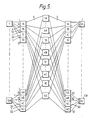
- Figs 3, 4 and 5 illustrate a typical example of such reconfiguration, but assuming a rather smaller network than that of Fig. 2.
- the network is as in Fig. 5, and is capable of greater growth to 256 input and 256 output ports by the addition of more terminals and also first and third stage switches.
- the main part of the cost at the time of reconfiguration is that of the extra second stage paths needed.
- the division of the switching network into segments or sub-networks improves the operating flexibility of the network in an economical manner.
- it permits automatic reconfigurations, under the control of the central control (not shown), when path failure is detected.
- It also permits diversion of traffic under manual instruction to the central control with minimum, if any, disturbance to existing connections.
- one terminal card serves four input and four output ports.
- the terminal cards which each serve four inlet and four outlet ports, receive instructions from duplicated control busses and also have their own secured or unsecured "on card" converter for power.
- a complete segment or sub-network may receive instructions from duplicated command busses and may have its own converter for power.
- the inlet ports are associated with outlet ports.
- a digital line termination card mounts four inlet and outlet ports associated with four line terminations. In most cases these operate at a 2 Mb/s rate although in some instances the digital line terminations may operate, e.g. at 8 Mb/s rate. In some cases both 2 Mb/s and 8 Mb/s systems may operate on the same switch, but in such applications, paths are only connected between inlet and outlet terminals of like-rate.
- the port cards are connected to two central controllers, for control (Fig. 6), by serial shelf busses. In other embodiments a single shelf controller per shelf is connected via two message interfaces per rack to the duplicate controllers of the central control.
- the shelf controller then controls digital line termination cards on the shelf, see Fig. 7, except when it has failed and control is via the shelf controller of an adjacent shelf.
- a secured power supply and distribution may be used to power all the units on the shelf, or each line termination card has a DC to DC converter to convert from the rails supplied to it from battery to the 5 volts used by the logic.
- a four segment switch is described here, the first and third stage switches are 4 in number, each of which is 32 in by 16 out, and 4 in number, each of which is 16 in by 32 out respectively.
- the second stage switches are 32 x 32.
- the switch as in Fig. 2 can switch between 1024 input ports and 1024 output ports.
- a system in which the first and third stages are 48 x 96 switches rather than the 32 x 64 considered here is preferred.
- 3 segments, not four, may be used; then it is possible to serve larger number of ports, e.g. up to 4,600 input and 4,600 output ports.
- Figs. 3 to 5 show how by the techniques implicitly available in the design we may grow from small to large applications in an economic manner within a growth range, by providing additional first and third stages and ports as justified to the traffic served. Without the reconfiguration feature this leads to the provision of 64 second stage switches being used in the application shown in Fig. 3 instead of eight. Although these involve less crosspoints than the number of crosspoints needed for the second stage switch at large sizes but with VLSI techniques, the number of crosspoints on a chip is not the important factor in respect of cost, rather is it the number of second stage switches which count in determining the cost.
- the network is segmented into n segments, and with the software arrangement techniques available for use by the control, it is possible to operate the arrangement in live traffic on (n-1) segments.
- reconfiguration e.g. from Fig. 3 to an arrangement as shown in Fig. 4, takes place it is later possible to extend the growth range from that implicit in the configuration of Fig. 3 to that of Fig. 5.
- Each reconfiguration may involve e.g. the provision of twice as many second stages, and the reconfiguration of the links between first and second and between second and third stages of the switch.
- the links between these stages use twisted pairs, and rearrangement of the links between first and second and second and third stages may be afforded by the use of different back to back plugs for the different growth ranges.
- We may reconfigure segment D from that in Fig. 3 to that in Fig. 4 when :
- the links between the first and second and between the second and third stages of segment D are then reconfigured with the addition of two more second stage switches, and the set up of the paths is effected corresponding to the paths before reconfiguration has occurred.
- Each second stage switch provided in this Figure serves eight first stage switches (see Fig. 2) and therefore there are 8 links connecting stage 1A (First Stage) to stage 2A (Second Stage). In the case shown in Fig. 5 there are 4 links connecting 1A (First stage) to stage 2A (Second Stage). After a further reconfiguration there would be two.
- Fig. 8 The trunking diagram for a cross-connect frame with a single switching arrangement embodying the invention is shown in Fig. 8, which shows a system with four switch planes for the first and third stages of a three stage network.
- the first stage includes a number of line termination units LT, each of which is a digital line termination (DLT), to/from transmission, or a bridge link termination (BLT), to/from 64 kb/s layer of the system considered.
- Each first/third stage serves 64 incoming and 64 outgoing ports, which may include 32 DLT cards and 32 BLT cards.
- each block of the first/third stage includes four 64 x 32 matrix assemblies, and as shown half the blocks act as incoming switches and half the blocks as outgoing switches.
- the middle stages M1-M32 are each e.g. 32 x 32 assemblies effectively in four segments, and the inter stage cabling connections can be varied as needed when the system size varies.
- the basic principles of the system can also be extended to four and five stage arrays. In all cases the system can be installed partly equipped so that when more lines have to be served, the alterations needed to the network are simple.
- Fig. 8 assumes four segments A, B, C and D, of which the sets of switches connected to the uppermost LT block form segment A, segments B and C are not shown, and the two sets of switches connected to the lowermost LT block form segment D.
Landscapes
- Engineering & Computer Science (AREA)
- Computer Networks & Wireless Communication (AREA)
- Data Exchanges In Wide-Area Networks (AREA)
- Use Of Switch Circuits For Exchanges And Methods Of Control Of Multiplex Exchanges (AREA)
- Monitoring And Testing Of Exchanges (AREA)
Applications Claiming Priority (2)
| Application Number | Priority Date | Filing Date | Title |
|---|---|---|---|
| GB8607951 | 1986-04-01 | ||
| GB8607951A GB2188813B (en) | 1986-04-01 | 1986-04-01 | Switching network |
Publications (2)
| Publication Number | Publication Date |
|---|---|
| EP0240211A2 true EP0240211A2 (de) | 1987-10-07 |
| EP0240211A3 EP0240211A3 (de) | 1989-07-12 |
Family
ID=10595492
Family Applications (1)
| Application Number | Title | Priority Date | Filing Date |
|---|---|---|---|
| EP87302416A Withdrawn EP0240211A3 (de) | 1986-04-01 | 1987-03-20 | Vermittlungsnetz |
Country Status (6)
| Country | Link |
|---|---|
| US (1) | US4811333A (de) |
| EP (1) | EP0240211A3 (de) |
| JP (1) | JPS62237849A (de) |
| AU (1) | AU586917B2 (de) |
| CA (1) | CA1267711A (de) |
| GB (1) | GB2188813B (de) |
Cited By (2)
| Publication number | Priority date | Publication date | Assignee | Title |
|---|---|---|---|---|
| EP0569906A3 (de) * | 1992-05-14 | 1995-05-24 | Alcatel Nv | Verfahren und System zum unmittelbaren Anschluss und Vermittlung eines digitalen Verzweigernetzes. |
| AU765132B2 (en) * | 1998-03-31 | 2003-09-11 | Nec Infrontia Corporation | Switching system for EAX including integrated first/third-stage switch |
Families Citing this family (22)
| Publication number | Priority date | Publication date | Assignee | Title |
|---|---|---|---|---|
| JPH07123314B2 (ja) * | 1986-05-09 | 1995-12-25 | 日本電気株式会社 | 無線通信装置 |
| CA1297567C (en) * | 1987-02-06 | 1992-03-17 | Kazuo Hajikano | Self routing-switching system |
| US4970505A (en) * | 1987-04-09 | 1990-11-13 | Nec Corporation | Three stage switching apparatus |
| DE3802579A1 (de) * | 1988-01-29 | 1989-08-10 | Ant Nachrichtentech | Dreistufiges blockierungsfreies koppelfeld |
| US5198808A (en) * | 1988-09-20 | 1993-03-30 | Nec Corporation | Matrix switch apparatus with a diagnosis circuit having stand-by ports and reduced size matrix switching elements |
| GB8824972D0 (en) * | 1988-10-25 | 1988-11-30 | Plessey Telecomm | Time division switch |
| US4952930A (en) * | 1988-11-18 | 1990-08-28 | International Business Machines Corp. | Multipath hierarchical network |
| US5040173A (en) * | 1989-05-08 | 1991-08-13 | At&T Bell Laboratories | Network control arrangement based on topological equivalence |
| DE3916720A1 (de) * | 1989-05-23 | 1990-11-29 | Ant Nachrichtentech | Verfahren zur erweiterung eines dreistufigen regelmaessigen koppelfeldes |
| DE4020775A1 (de) * | 1989-08-09 | 1991-02-14 | Standard Elektrik Lorenz Ag | Koppelnetz und koppelnetzmodul fuer ein atm-system |
| US5123011A (en) * | 1989-09-27 | 1992-06-16 | General Electric Company | Modular multistage switch for a parallel computing system |
| US5142686A (en) * | 1989-10-20 | 1992-08-25 | United Technologies Corporation | Multiprocessor system having processors and switches with each pair of processors connected through a single switch using Latin square matrix |
| US5369400A (en) * | 1992-05-14 | 1994-11-29 | Alcatel Network Systems, Inc. | Method and system for hitlessly rearranging connections in a cross-connect communications network |
| DE4224932A1 (de) * | 1992-07-28 | 1993-01-21 | Siemens Ag | Verfahren zur zuteilung der vermittlungstechnischen ressourcen eines kommunikationssystems fuer waehl- und festverbindungen |
| KR0126848B1 (ko) * | 1994-12-16 | 1998-04-01 | 양승택 | 다중화기와 역다중화기를 이용한 고정길이 패킷 스위칭 장치 |
| KR0145928B1 (ko) * | 1995-05-31 | 1998-08-17 | 유기범 | 전전자교환기에 있어서 출력데이타 충돌 방지가 가능한 메트릭스 스위치 장치 |
| JP3094849B2 (ja) * | 1995-06-21 | 2000-10-03 | 株式会社日立製作所 | 並列計算機およびその多段結合網 |
| US6396844B1 (en) * | 1998-10-09 | 2002-05-28 | Adtran, Inc. | Backplane architecture for providing both loop repeater and multiplexed mode connectivity in the same equipment shelf |
| DE10122422A1 (de) | 2001-05-09 | 2002-11-21 | Siemens Ag | Verfahren und Vorrichtung zum Einstellen der Bandbreite einer Verbindung zwischen mindestens zwei Kommunikationsendpunkten in einem Datennetz |
| US6766482B1 (en) | 2001-10-31 | 2004-07-20 | Extreme Networks | Ethernet automatic protection switching |
| FR3071119B1 (fr) * | 2017-09-11 | 2019-09-13 | Thales | Reseau de communication, systeme de mesure, moyen de transport et procede de construction d'un reseau de communication associes |
| US11657297B2 (en) * | 2018-04-30 | 2023-05-23 | Bank Of America Corporation | Computer architecture for communications in a cloud-based correlithm object processing system |
Family Cites Families (17)
| Publication number | Priority date | Publication date | Assignee | Title |
|---|---|---|---|---|
| US3582560A (en) * | 1968-08-02 | 1971-06-01 | Communications & Systems Inc | Multistage telephone switching system for different priority users |
| US3649768A (en) * | 1970-07-01 | 1972-03-14 | Bell Telephone Labor Inc | High capacity switching network and control arrangement |
| FR2180171A5 (de) * | 1972-04-11 | 1973-11-23 | Materiel Telephonique | |
| FR2188923A5 (de) * | 1972-06-01 | 1974-01-18 | Materiel Telephonique | |
| CA1028764A (en) * | 1973-03-19 | 1978-03-28 | L M Ericsson Pty. Ltd. | Data switching apparatus and method |
| GB1433160A (en) * | 1973-11-22 | 1976-04-22 | Plessey Co Ltt | Multistage switching networks for use in telecommunications exchanges |
| FR2279294A1 (fr) * | 1974-04-18 | 1976-02-13 | Labo Cent Telecommunicat | Reseau de commutation de messages codes multiplexes dans le temps |
| FR2302654A1 (fr) * | 1975-02-25 | 1976-09-24 | Thomson Csf | Autocommutateur a commutation temporelle, procede de reconfiguration d'un tel autocommutateur |
| US4004103A (en) * | 1975-10-15 | 1977-01-18 | Bell Telephone Laboratories, Incorporated | Path-finding scheme for a multistage switching network |
| FR2356322A1 (fr) * | 1976-06-22 | 1978-01-20 | Thomson Csf | Reseau de connexion temporel et spatial, et autocommutateur comprenant un tel reseau |
| US4201891A (en) * | 1978-03-17 | 1980-05-06 | International Telephone And Telegraph Corporation | Expandable digital switching network |
| US4345324A (en) * | 1980-07-09 | 1982-08-17 | Christian Rovsing A/S | Process and system for error detection in a computer-controlled telephone exchange |
| JPS5726955A (en) * | 1980-07-25 | 1982-02-13 | Hitachi Ltd | Backup control system |
| US4400627A (en) * | 1981-05-04 | 1983-08-23 | Bell Telephone Laboratories, Incorporated | Telephone switching network |
| US4417244A (en) * | 1981-09-01 | 1983-11-22 | International Business Machines Corp. | Automatic path rearrangement for blocking switching matrix |
| IT1159090B (it) * | 1982-09-01 | 1987-02-25 | Italtel Spa | Rete di commutazione pcm ridondata a ripartizione di traffico |
| US4654842A (en) * | 1984-08-02 | 1987-03-31 | Coraluppi Giorgio L | Rearrangeable full availability multistage switching network with redundant conductors |
-
1986
- 1986-04-01 GB GB8607951A patent/GB2188813B/en not_active Expired - Fee Related
-
1987
- 1987-03-20 EP EP87302416A patent/EP0240211A3/de not_active Withdrawn
- 1987-03-25 AU AU70634/87A patent/AU586917B2/en not_active Ceased
- 1987-03-30 JP JP62077381A patent/JPS62237849A/ja active Pending
- 1987-03-31 US US07/032,780 patent/US4811333A/en not_active Expired - Fee Related
- 1987-03-31 CA CA000533507A patent/CA1267711A/en not_active Expired - Fee Related
Cited By (2)
| Publication number | Priority date | Publication date | Assignee | Title |
|---|---|---|---|---|
| EP0569906A3 (de) * | 1992-05-14 | 1995-05-24 | Alcatel Nv | Verfahren und System zum unmittelbaren Anschluss und Vermittlung eines digitalen Verzweigernetzes. |
| AU765132B2 (en) * | 1998-03-31 | 2003-09-11 | Nec Infrontia Corporation | Switching system for EAX including integrated first/third-stage switch |
Also Published As
| Publication number | Publication date |
|---|---|
| GB8607951D0 (en) | 1986-05-08 |
| JPS62237849A (ja) | 1987-10-17 |
| US4811333A (en) | 1989-03-07 |
| GB2188813B (en) | 1990-03-14 |
| CA1267711A (en) | 1990-04-10 |
| GB2188813A (en) | 1987-10-07 |
| AU7063487A (en) | 1987-10-08 |
| EP0240211A3 (de) | 1989-07-12 |
| AU586917B2 (en) | 1989-07-27 |
Similar Documents
| Publication | Publication Date | Title |
|---|---|---|
| US4811333A (en) | Substantially non-blocking space switching arrangement | |
| US5751574A (en) | Method for loading software in communication systems with non-redundant, decentralized equipment | |
| US4455645A (en) | Back-up control system implemented with a redundancy scheme for protection against failure | |
| EP0400879B1 (de) | Dynamisch verteiltes System für private Netze | |
| EP0228204B1 (de) | Architektur von Nachrichtenvermittlungssystemen mit verteilter Steuerung | |
| CA1270958A (en) | Resource allocation in distributed control systems | |
| US6377374B1 (en) | Method apparatus and computer program product for optical network restoration | |
| US3912873A (en) | Multiple fault tolerant digital switching system for an automatic telephone system | |
| US4254498A (en) | Time division telephone switching systems | |
| US3920914A (en) | Divided time-division switching network | |
| US5901024A (en) | Apparatus and method for circuit protection | |
| US5459606A (en) | In-service upgrade for a telecommunication system | |
| JPH07105799B2 (ja) | 電気通信網 | |
| US4905222A (en) | Circuit arrangement for centrally controlled time division multiplex telecommunication switching systems, particularly PCM-telephone switching systems with line trunk groups connected to a switching matrix | |
| EP0132916B1 (de) | Kommunikationssystem | |
| US4964105A (en) | Replacement switch | |
| JPS6349959B2 (de) | ||
| US4901347A (en) | Circuit arrangement for telecommunication switching systems, particularly PCM-time-division multiplex telephone switching systems with a central matrix and with local sub-switching matrices connected to the same | |
| US4853957A (en) | Telecommunication switching systems with a central switching and local sub-switching | |
| JP3139424B2 (ja) | T−s−t3段スイッチ制御方式 | |
| US5461613A (en) | Method for preparing de-centralized redundant units in a communications system to be placed in service | |
| Ash et al. | Network routing evolution | |
| JPS6337999B2 (de) | ||
| US6529599B1 (en) | Flexible tributary unit protection method for a trunk-multiplexed metallic interface | |
| JP3465212B2 (ja) | 分散形時分割通話路方式 |
Legal Events
| Date | Code | Title | Description |
|---|---|---|---|
| PUAI | Public reference made under article 153(3) epc to a published international application that has entered the european phase |
Free format text: ORIGINAL CODE: 0009012 |
|
| AK | Designated contracting states |
Kind code of ref document: A2 Designated state(s): BE CH DE FR IT LI NL SE |
|
| PUAL | Search report despatched |
Free format text: ORIGINAL CODE: 0009013 |
|
| AK | Designated contracting states |
Kind code of ref document: A3 Designated state(s): BE CH DE FR IT LI NL SE |
|
| 17P | Request for examination filed |
Effective date: 19890710 |
|
| STAA | Information on the status of an ep patent application or granted ep patent |
Free format text: STATUS: THE APPLICATION IS DEEMED TO BE WITHDRAWN |
|
| 18D | Application deemed to be withdrawn |
Effective date: 19911003 |
|
| RIN1 | Information on inventor provided before grant (corrected) |
Inventor name: REES, FREDERICK HENRY |