EP0240128B1 - Einrichtung und Verfahren zur Bereitstellung eines konstanten Metallschmelzspiegels in einer gasdurchlässigen Maskenform für Metallguss - Google Patents
Einrichtung und Verfahren zur Bereitstellung eines konstanten Metallschmelzspiegels in einer gasdurchlässigen Maskenform für Metallguss Download PDFInfo
- Publication number
- EP0240128B1 EP0240128B1 EP87301448A EP87301448A EP0240128B1 EP 0240128 B1 EP0240128 B1 EP 0240128B1 EP 87301448 A EP87301448 A EP 87301448A EP 87301448 A EP87301448 A EP 87301448A EP 0240128 B1 EP0240128 B1 EP 0240128B1
- Authority
- EP
- European Patent Office
- Prior art keywords
- furnace
- mold
- molten metal
- level
- metal
- Prior art date
- Legal status (The legal status is an assumption and is not a legal conclusion. Google has not performed a legal analysis and makes no representation as to the accuracy of the status listed.)
- Expired
Links
- 239000002184 metal Substances 0.000 title claims description 84
- 229910052751 metal Inorganic materials 0.000 title claims description 84
- 238000000034 method Methods 0.000 title claims description 14
- 238000005058 metal casting Methods 0.000 title description 3
- 238000005266 casting Methods 0.000 claims description 24
- 230000008859 change Effects 0.000 claims description 13
- 230000006698 induction Effects 0.000 claims description 10
- 238000002844 melting Methods 0.000 claims description 9
- 230000008018 melting Effects 0.000 claims description 9
- 238000010112 shell-mould casting Methods 0.000 claims description 9
- 230000004044 response Effects 0.000 claims description 4
- 239000007787 solid Substances 0.000 claims description 2
- 230000003287 optical effect Effects 0.000 claims 2
- 239000007789 gas Substances 0.000 description 10
- 239000011261 inert gas Substances 0.000 description 4
- 229910001338 liquidmetal Inorganic materials 0.000 description 4
- 230000008569 process Effects 0.000 description 4
- 238000005272 metallurgy Methods 0.000 description 3
- 150000002739 metals Chemical class 0.000 description 3
- 238000010276 construction Methods 0.000 description 2
- 230000000694 effects Effects 0.000 description 2
- 238000005495 investment casting Methods 0.000 description 2
- 229910001141 Ductile iron Inorganic materials 0.000 description 1
- 239000000919 ceramic Substances 0.000 description 1
- 238000010586 diagram Methods 0.000 description 1
- 239000012530 fluid Substances 0.000 description 1
- 230000004907 flux Effects 0.000 description 1
- 239000012535 impurity Substances 0.000 description 1
- 238000004519 manufacturing process Methods 0.000 description 1
- 238000005259 measurement Methods 0.000 description 1
- 239000011819 refractory material Substances 0.000 description 1
- 239000000523 sample Substances 0.000 description 1
Images

Classifications
-
- B—PERFORMING OPERATIONS; TRANSPORTING
- B22—CASTING; POWDER METALLURGY
- B22D—CASTING OF METALS; CASTING OF OTHER SUBSTANCES BY THE SAME PROCESSES OR DEVICES
- B22D18/00—Pressure casting; Vacuum casting
- B22D18/08—Controlling, supervising, e.g. for safety reasons
-
- B—PERFORMING OPERATIONS; TRANSPORTING
- B22—CASTING; POWDER METALLURGY
- B22D—CASTING OF METALS; CASTING OF OTHER SUBSTANCES BY THE SAME PROCESSES OR DEVICES
- B22D18/00—Pressure casting; Vacuum casting
- B22D18/06—Vacuum casting, i.e. making use of vacuum to fill the mould
Definitions
- This invention relates to a metal casting apparatus and methods which employ gas permeable shell mold according to the preambles of claim1 and 15, respectively.
- Gas permeable shell mold casting for casting of metal in an evacuated/inert gas atmosphere is known and was developed to permit precision casting, on a high production basis, of metals which must be cast in an evacuated or inert gas atmosphere.
- precision casting of metals in an evacuated or inert gas atmosphere presented a number of problems. In part, those problems were due to the time necessary to establish the required seals and to evacuate the casting apparatus, especially insofar as the relatively large melting and pouring chamber was concerned. There were also problems caused by the inclusion in the cast parts of dross or other impurities present on the surface of the molten metal.
- US Patent No. 3 863 706 describes gas permeable shell mold casting, in which is disclosed apparatus comprising a furnace for melting and holding metal to be cast, a mold which is relatively movable between a position above the furnace and a casting position in which the mold is in casting relationship with the molten metal in the furnace, means for locating the mold to be filled in the casting relationship with the molten metal in the furnace, and means for causing molten metal to be drawn from the furnace means into the mold.
- the present invention comprises such apparatus and is characterized by a level sensor for sensing the change in the level of the molten metal in the furnace relative to the mold as molten metal is drawn into the mold, and means responsive to the sensor are provided for causing the furnace and the mold to move relative to one another for causing the level of the molten metal to remain constant relative to the mold as the mold is being filled, for providing a constant level of molten metal to a mold in gas permeable shell mold casting.
- the US Patent also describes a method of providing a constant level of molten metal to a mold in gas permeable shell mold casting, comprising the steps of melting and holding metal to be cast in a furnace, locating a mold to be filled in casting relationship with the molten metal in the furnace and causing molten metal to be drawn from the furnace into the mold, and the present invention comprises such method characterized by sensing the change in the level of the molten metal in the furnace relative to the mold as molten metal is drawn into the mold, and causing the furnace to move relative to the mold, in response to change in the level of the molten metal relative to the mold, to cause the level of the molten metal to remain constant relative to the mold as the mold is being filled.
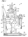
- furnace 12 for melting and holding metal to be cast.
- furnace 12 comprises a housing or shell 14 and a crucible 16 constructed of a suitable refractory material, such as a high temperature ceramic, within the shell 14.
- Furnace 12 is provided with a plurality of induction coils 18 surrounding crucible 16 and through which high frequency electric current is passed to inductively heat and melt the metal to be cast.
- Induction coils 18 are connected to a suitable source of electrical power (not shown in Figure I) in known manner.
- furnace 12 includes a pair of arms 20 and 22 on opposite side of the furnace by means of which furnace 12 may be mounted to a support structure or frame 24.
- Frame 24 comprises a pair of upright standards 26 and 28 which are mounted on horizontal support members 30 and 32.
- Arms 20 and 22, which are fixed to furnace 12, are pivotably mounted to standards 26 and 28 as shown at locations 34 and 36.
- Pivot locations 34 and 36 may have any suitable structure for providing a 'pivotable connection between arms 20 and 22 and standards 26 and 28.
- a pivot axis 38 about which furnace 12 may tilt, as will be described in greater detail below, is defined through pivot locations 34 and 36, as best seen in Figure 4.
- the ends of arms 20 and 22 opposite pivot locations 34 and 36 are connected to cylinders 40 and 42, respectively.
- Cylinders 40 and 42 may be pneumatic or hydraulic, and include extensible/retractable cylinder rods 44 and 46, respectively.
- Rods 44 and 46 are extensible and retractable by cylinders 40 and 42 in known manner, and have their free ends pivotably connected to arms 20 and 22 at pivot locations 48 and 50, respectively.
- the opposite end of cylinders 40 and 42 are pivotably connected to base 30, as at location 52 in Figure I.
- Cylinders 40 and 42 may be connected to a source of pneumatic or hyraulic fluid by suitable valving and connections, in known manner.
- Horizontal support members 30 and 32 may be provided with wheels 54 and mounted on track members 56 and 58 so that furnace 12 can be moved left to right with respect to casting machine 10 in Figure I. Movement of furnace 12 can be accomplished by cylinder 60, as will be understood by those skilled in the art.
- a stop member 62 may be provided on casting machine 10 to limit movement of furnace 12 to the left (as viewed in Figure I) and to properly position furnace 12 with respect to casting machine 10.
- casting machine also includes a head 64 in which may be located a gas permeable shell mold 66.
- Head 64 is connected by a vacuum line (not shown) to a vacuum pump (not shown), by means of which a vacuum may be drawn on mold 66 so that molten metal may be drawn into the mold, in known manner.
- Head 64 and mold 66 may be moved vertically toward and away from furnace 12 by means of cylinder 70 and rod 72, in known manner.
- Guide rods 74 and 76 are provided in tubular guides 78 and 80 so that head 64 and mold 66 can be moved straight up and down and will not be skewed when head 64 and mold 66 are raised or lowered.
- Level sensor 100 may be mounted on a standard 102 which is fixed with respect to casting machine 10.
- Level sensor 100 may be any suitable remote level sensor, such as a laser level sensor, familiar to those skilled in the art.
- Standard 102 and level sensor 100 are located so that the level sensor has a clear line of sight to the level of molten metal in the furnace, unobstucted either by head 64 or the edge of the furnace when the furnace is tilted.
- Casting machine 10 may also be supplied with a suitable charge system for adding metal to be melted to furnace 12. Alternatively, liquid metal may be added directly. Any suitable charge system, such as a conveyor system, may be employed. Charge for furnace 12 is directed into crucible 16 via a chute 104. Chute 104 may be pivoted as at location 106, so that chute 104 may pivot out of the way to allow for tilting of furnace 12.
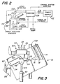
- the apparatus of the invention is shown schematically in Figure 2.
- the central controller for the invention is computer 108, which may be a mini-computer or dedicated microprocessor suitably programmed to carry out the operations of the invention.
- computer 108 receives the output signal from level detector 100 and the output of a shaft position encoder 110, which is not shown in Figures I or 4, but which may be mounted on furnace 12 along pivot axis 38 to sense the angle through which furnace 12 is tilted.
- Shaft encoders for sensing angular position are well known, and need not be described in detail here.
- An additional input to computer 108 is a signal from a temperature sensor which senses the temperature of the metal in the furnace. Temperature of the molten metal may be sensed by any suitable means, such as a contact probe or infrared pyrome- ter. This measurement may be made separately and the results inputted to computer 108 by a conventional keyboard (not shown).
- computer 108 In response to the inputs, computer 108 generates a number of control outputs for the apparatus. One output is a control signal to the furnace power supply 112 to control the power being supplied to induction coils 18 of furnace 12.
- Computer 108 controls power supply 112 so that a predetermined temperature of the molten metal in the furance may be maintained, and so that additional power may be supplied to furnace 12 for melting when furnace 12 is charged with cold metal.
- the way in which computer 108 may control power supply 112 for these functions will be well understood by those skilled in the art, and need not be described here in detail.
- Computer 108 also processes the signals from level sensor 100 and shaft encoder 110 and generates a tilt control output, which is used to control the operation of cylinder 40.
- furnace 12 After furnace 12 has been charged with and melted the metal to be cast, or has been charged with liquid metal, head 64 and mold 66 are lowered into furnace 12 so that mold 66 is partially immersed in the molten metal 114. A vacuum is then drawn on mold 66 to draw molten metal into the mold.
- Level sensor 100 continuously monitors the level 116 of molten metal 114 relative to mold 66. It will be appreciated that, as molten metal is drawn up into mold 66, level 116 will drop. The change in level 116 is sensed by level sensor 100, and a signal representative of the change in level 116 is sent to computer 108. Computer 108 processes this signal and generates a tilt control signal which, through appropriate hyraulic or pneumatic lines and valving causes cylinder 40 to extend shaft 44. As shaft 44 is extended, furnace 12 tilts about pivot axis 38. See Figure 3. Tilting furnace 12 in effect raises the level 116 of molten metal 114 with respect to mold 66. Computer 108 may be programmed to continuously tilt furnace 12 as molten metal is drawn up into mold 66, with the effect that the level 116 of molten metal 114 remains constant with respect to mold 66.
- mold 66 When the mold 66 is full, it is withdrawn from furnace 12, and casting machine 10 sends a signal to computer 108 that the casting operation is complete. When the casting operation is complete, head 64 and mold 66 are raised out of furnace 12, a new mold is placed in head 64, and the process repeated.
- Computer 108 may be programmed to control the operation of the charge system so that additional charge may be added to furnace 12 to continually replenish the metal being drawn into mold 66.
- the shaft position encoder signal is processed by computer 108 to determine whether the angle of tilt of furnace 12 is sufficiently large that more metal should be added. If so, computer 108 activates the charge system, charging additional metal into the furnace.
- the computer 108 will maintain level 116 constant as metal is charged into the furnace by reducing the angle of tilt of the furnace.
- the change in angle of tilt of the furnace is continuously sensed by shaft position encoder 110.
- computer 108 terminates the charging operation.
- the computer 108 calculates the total charge being placed in the furnace by the change in angle of tilt, and signals power supply 112 to maintain an average power level in furnace 12 so that cold metal can be melted and temperature stability is maintained.
- Computer 108 may be programmed to stop the tilting of furnace 12 after furnace 12 has been tilted for a preselected number of degrees. When furnace 12 has been tilted to the preselected number of degrees, as indicated by shaft position encoder 110, computer 108 will stop the tilting of furnace 12, and reverse the drive to cylinder 40. Cylinder 40 will then retract rod 44, allowing furnace 12 to be tilted back to its original horizontal position.
- the change in level 116 sensed by level sensor 100 may be processed to generate a signal representative of the change in level 116.
- This signal is sent to computer 108, which processes this signal and generates a lift control signal that controls the vertical position of mold 66 relative to level 116 of liquid metal 114.
- furnace 12 remains in a horizontal position and no tilting takes place. Instead, as level 116 falls as metal is drawn into mold 66, the mold is lowered to keep level 116 constant relative to mold 66. When the level 116 falls below a predetermined value, level control 100 sends a signal to computer 108 and either solid or liquid metal is added to the furnace.
- the furnace 12 needs to have a very large surface area to accomodate mold 66.
- metal especially ductile iron, for example, it is important to have the minimum quantity of metal on hand at the casting station. This is because changes in metallurgy of the molten metal can occur over time which affect the quality of the end casting. The longer the "dwell time" of the molten metal in furnace 12, the greater the changes in metallurgy will be. To minimize "dwell time", a very small depth of metal is preferred in this casting process.
- Furnace 12' in Figure 5 comprises a furnace shell 14' within which is a crucible 16'. As shown in Figure 5, the interior of crucible 16' is very shallow. Surrounding crucible 16' within shell 14' are induction coils 18'.
- the load length and coil length are equal.
- the coil length is made much longer than the load. So as not to allow stray flux to heat the mold surroundings, the minimum metal level is held to the top of the induction coil.
- the induction coil 18' extends far below the metal. The bottom turns of the coil 18' couple magnetically to the bottom of the molten metal and, thus, act as if both the load and coil were very much longer than the load depth.
- the furnace of Figure 5 thus enables very small depths of metal to be melted and/or held at very high efficiencies, which in turn allows "dwell time” and changes in metallurgy to be minimized.
Landscapes
- Engineering & Computer Science (AREA)
- Mechanical Engineering (AREA)
- Casting Support Devices, Ladles, And Melt Control Thereby (AREA)
- Crucibles And Fluidized-Bed Furnaces (AREA)
- General Induction Heating (AREA)
- Furnace Details (AREA)
Claims (19)
Applications Claiming Priority (2)
| Application Number | Priority Date | Filing Date | Title |
|---|---|---|---|
| US06/848,675 US4673025A (en) | 1986-04-04 | 1986-04-04 | Apparatus and method for maintaining constant molten metal level in metal casting |
| US848675 | 1986-04-04 |
Publications (3)
| Publication Number | Publication Date |
|---|---|
| EP0240128A2 EP0240128A2 (de) | 1987-10-07 |
| EP0240128A3 EP0240128A3 (en) | 1988-01-20 |
| EP0240128B1 true EP0240128B1 (de) | 1989-10-04 |
Family
ID=25303978
Family Applications (1)
| Application Number | Title | Priority Date | Filing Date |
|---|---|---|---|
| EP87301448A Expired EP0240128B1 (de) | 1986-04-04 | 1987-03-05 | Einrichtung und Verfahren zur Bereitstellung eines konstanten Metallschmelzspiegels in einer gasdurchlässigen Maskenform für Metallguss |
Country Status (5)
| Country | Link |
|---|---|
| US (1) | US4673025A (de) |
| EP (1) | EP0240128B1 (de) |
| JP (2) | JPS62267059A (de) |
| CA (2) | CA1301224C (de) |
| DE (1) | DE3760654D1 (de) |
Families Citing this family (9)
| Publication number | Priority date | Publication date | Assignee | Title |
|---|---|---|---|---|
| US4744407A (en) * | 1986-10-20 | 1988-05-17 | Inductotherm Corp. | Apparatus and method for controlling the pour of molten metal into molds |
| IN170880B (de) * | 1987-05-07 | 1992-06-06 | Metal Casting Tech | |
| US4932461A (en) * | 1988-01-25 | 1990-06-12 | General Motors Corporation | Countergravity casting apparatus |
| US4858672A (en) * | 1988-05-25 | 1989-08-22 | General Motors Corporation | Countergravity casting apparatus and method |
| US6516862B2 (en) | 2001-03-30 | 2003-02-11 | Northrop Grumman Corporation | Method of fabricating a mold-cast porous metal structure |
| AT504079B1 (de) * | 2006-09-13 | 2008-09-15 | Siemens Vai Metals Tech Gmbh | Verfahren zum abgiessen von schmelze aus einem kippbaren metallurgischen gefäss sowie anlage zur durchführung des verfahrens |
| US8915733B2 (en) * | 2010-11-11 | 2014-12-23 | Air Products And Chemicals, Inc. | Selective adjustment of heat flux for increased uniformity of heating a charge material in a tilt rotary furnace |
| DE102016107278A1 (de) * | 2016-04-20 | 2017-10-26 | Chemex Gmbh | Speisereinsatz mit Sensoröffnung, sowie Speiser-Anordnung, Verwendung und Verfahren |
| WO2023076642A1 (en) * | 2021-10-29 | 2023-05-04 | MolyWorks Materials Corporation | Tilting melting hearth system and method for recycling metal |
Citations (1)
| Publication number | Priority date | Publication date | Assignee | Title |
|---|---|---|---|---|
| US3863706A (en) * | 1972-12-04 | 1975-02-04 | Hitchiner Manufacturing Co | Metal casting |
Family Cites Families (9)
| Publication number | Priority date | Publication date | Assignee | Title |
|---|---|---|---|---|
| CH561091A5 (de) * | 1972-03-17 | 1975-04-30 | Aeg Elotherm Gmbh | |
| JPS4977242A (de) * | 1972-11-28 | 1974-07-25 | ||
| US4230308A (en) * | 1978-03-22 | 1980-10-28 | Eugene Gueguen | Automated casting line supply system |
| JPS5615518U (de) * | 1979-07-16 | 1981-02-10 | ||
| JPS58199654A (ja) * | 1982-05-14 | 1983-11-21 | Toyota Motor Corp | 吸引鋳造制御方法及び装置 |
| JPS591060A (ja) * | 1982-06-25 | 1984-01-06 | Toyota Motor Corp | 減圧吸引鋳造制御方法及び装置 |
| DE3412126A1 (de) * | 1984-03-31 | 1985-10-10 | Clemens-A. Dipl.-Ing. 5600 Wuppertal Verbeek | Verfahren und einrichtung zum restfreien herstellen frei gewaehlter schmelzmengen |
| DE3532763A1 (de) * | 1984-09-15 | 1986-03-27 | Gebr. Wöhr GmbH und Co KG, 7080 Aalen | Verfahren und vorrichtung zum automatischen vergiessen von fluessigem metall |
| JPH1060A (ja) * | 1996-06-17 | 1998-01-06 | Nippon Flour Mills Co Ltd | 包装飼料及びその製造方法 |
-
1986
- 1986-04-04 US US06/848,675 patent/US4673025A/en not_active Expired - Lifetime
-
1987
- 1987-02-17 CA CA000529887A patent/CA1301224C/en not_active Expired - Lifetime
- 1987-03-05 DE DE8787301448T patent/DE3760654D1/de not_active Expired
- 1987-03-05 EP EP87301448A patent/EP0240128B1/de not_active Expired
- 1987-03-19 JP JP62062776A patent/JPS62267059A/ja active Granted
-
1990
- 1990-08-03 JP JP2205311A patent/JPH0812036B2/ja not_active Expired - Lifetime
-
1991
- 1991-07-16 CA CA000616117A patent/CA1318937C/en not_active Expired - Lifetime
Patent Citations (1)
| Publication number | Priority date | Publication date | Assignee | Title |
|---|---|---|---|---|
| US3863706A (en) * | 1972-12-04 | 1975-02-04 | Hitchiner Manufacturing Co | Metal casting |
Also Published As
| Publication number | Publication date |
|---|---|
| US4673025A (en) | 1987-06-16 |
| CA1301224C (en) | 1992-05-19 |
| JPH0442111B2 (de) | 1992-07-10 |
| EP0240128A3 (en) | 1988-01-20 |
| CA1318937C (en) | 1993-06-08 |
| JPS62267059A (ja) | 1987-11-19 |
| JPH03234346A (ja) | 1991-10-18 |
| DE3760654D1 (en) | 1989-11-09 |
| EP0240128A2 (de) | 1987-10-07 |
| JPH0812036B2 (ja) | 1996-02-07 |
Similar Documents
| Publication | Publication Date | Title |
|---|---|---|
| EP0240128B1 (de) | Einrichtung und Verfahren zur Bereitstellung eines konstanten Metallschmelzspiegels in einer gasdurchlässigen Maskenform für Metallguss | |
| US2709842A (en) | Apparatus for continuous casting of high-melting-point metals | |
| EP1133592B1 (de) | Verfahren zur steuerung der züchtung eines siliziumkristalles | |
| US4745620A (en) | Apparatus and method for maintaining constant molten metal level in metal casting | |
| US5033948A (en) | Induction melting of metals without a crucible | |
| US5309976A (en) | Continuous pour directional solidification method | |
| AU699470B2 (en) | Method and device for directly charging an electric furnace with liquid metal from a ladle | |
| EP1097013B1 (de) | Verfahren und vorrichtung für den steigenden guss von metall | |
| CA1313894C (en) | Apparatus and method for maintaining constant molten metal level in metal casting | |
| US5014769A (en) | Induction melting of metals without a crucible | |
| RU2319752C2 (ru) | Способ индукционной плавки литья металлов и устройство для его осуществления | |
| KR20230051263A (ko) | 단결정의 제조 방법 | |
| US3035106A (en) | Construction and operation of electric tilting furnaces | |
| JPH04310534A (ja) | 鉱物繊維製造方法及び装置 | |
| EP0511465A3 (en) | Electromagnetic agitating method for continuous casting | |
| JPH11180711A (ja) | 溶融シリコンの鋳型注湯方法及び装置 | |
| JPH0639504A (ja) | タンディッシュ内溶鋼プラズマ加熱制御装置 | |
| JPH08185972A (ja) | 溶融金属のプラズマ加熱方法および装置 | |
| JPH1019682A (ja) | 精密鋳造用連続測温装置 | |
| US3643726A (en) | Electric slag remelting process and apparatus for producing metal ingots having a change in transverse dimension | |
| US4289192A (en) | Method and apparatus for producing a solid-section ingot by electroslag remelting | |
| JPH0650794A (ja) | 金属溶湯面のレベル検出装置 | |
| SU1092352A1 (ru) | Печь дл выплавки сплавов | |
| KR0175544B1 (ko) | Mn-Zn 페라이트 단결정 잉고트 육성장치 및 그 육성방법 | |
| JPH0741372B2 (ja) | 連続鋳造炉 |
Legal Events
| Date | Code | Title | Description |
|---|---|---|---|
| PUAI | Public reference made under article 153(3) epc to a published international application that has entered the european phase |
Free format text: ORIGINAL CODE: 0009012 |
|
| AK | Designated contracting states |
Kind code of ref document: A2 Designated state(s): DE FR GB |
|
| PUAL | Search report despatched |
Free format text: ORIGINAL CODE: 0009013 |
|
| AK | Designated contracting states |
Kind code of ref document: A3 Designated state(s): DE FR GB |
|
| 17P | Request for examination filed |
Effective date: 19880301 |
|
| 17Q | First examination report despatched |
Effective date: 19880630 |
|
| GRAA | (expected) grant |
Free format text: ORIGINAL CODE: 0009210 |
|
| AK | Designated contracting states |
Kind code of ref document: B1 Designated state(s): DE FR GB |
|
| REF | Corresponds to: |
Ref document number: 3760654 Country of ref document: DE Date of ref document: 19891109 |
|
| ET | Fr: translation filed | ||
| PLBE | No opposition filed within time limit |
Free format text: ORIGINAL CODE: 0009261 |
|
| STAA | Information on the status of an ep patent application or granted ep patent |
Free format text: STATUS: NO OPPOSITION FILED WITHIN TIME LIMIT |
|
| 26N | No opposition filed | ||
| REG | Reference to a national code |
Ref country code: GB Ref legal event code: IF02 |
|
| PGFP | Annual fee paid to national office [announced via postgrant information from national office to epo] |
Ref country code: DE Payment date: 20040331 Year of fee payment: 18 |
|
| PG25 | Lapsed in a contracting state [announced via postgrant information from national office to epo] |
Ref country code: DE Free format text: LAPSE BECAUSE OF NON-PAYMENT OF DUE FEES Effective date: 20051001 |
|
| PGFP | Annual fee paid to national office [announced via postgrant information from national office to epo] |
Ref country code: GB Payment date: 20060301 Year of fee payment: 20 |
|
| PGFP | Annual fee paid to national office [announced via postgrant information from national office to epo] |
Ref country code: FR Payment date: 20060308 Year of fee payment: 20 |
|
| PG25 | Lapsed in a contracting state [announced via postgrant information from national office to epo] |
Ref country code: GB Free format text: LAPSE BECAUSE OF EXPIRATION OF PROTECTION Effective date: 20070304 |
|
| REG | Reference to a national code |
Ref country code: GB Ref legal event code: PE20 |