EP0240045A1 - Kompaktes Durchsichtprotektionssystem mit schief einfallendem Lichtbündel - Google Patents
Kompaktes Durchsichtprotektionssystem mit schief einfallendem Lichtbündel Download PDFInfo
- Publication number
- EP0240045A1 EP0240045A1 EP87200338A EP87200338A EP0240045A1 EP 0240045 A1 EP0240045 A1 EP 0240045A1 EP 87200338 A EP87200338 A EP 87200338A EP 87200338 A EP87200338 A EP 87200338A EP 0240045 A1 EP0240045 A1 EP 0240045A1
- Authority
- EP
- European Patent Office
- Prior art keywords
- projection
- plate
- prism
- light
- prism plate
- Prior art date
- Legal status (The legal status is an assumption and is not a legal conclusion. Google has not performed a legal analysis and makes no representation as to the accuracy of the status listed.)
- Withdrawn
Links
- 230000001154 acute effect Effects 0.000 claims description 2
- 239000006185 dispersion Substances 0.000 description 4
- 239000000463 material Substances 0.000 description 4
- 230000003287 optical effect Effects 0.000 description 4
- 238000010276 construction Methods 0.000 description 2
- 230000000875 corresponding effect Effects 0.000 description 2
- 238000009826 distribution Methods 0.000 description 2
- 230000000694 effects Effects 0.000 description 2
- 239000011159 matrix material Substances 0.000 description 2
- 210000001747 pupil Anatomy 0.000 description 2
- 241001135931 Anolis Species 0.000 description 1
- 230000006978 adaptation Effects 0.000 description 1
- 229910052729 chemical element Inorganic materials 0.000 description 1
- 239000003086 colorant Substances 0.000 description 1
- 239000002131 composite material Substances 0.000 description 1
- 238000011038 discontinuous diafiltration by volume reduction Methods 0.000 description 1
- 238000006073 displacement reaction Methods 0.000 description 1
- 238000000034 method Methods 0.000 description 1
- 230000005855 radiation Effects 0.000 description 1
Images


Classifications
-
- H—ELECTRICITY
- H04—ELECTRIC COMMUNICATION TECHNIQUE
- H04N—PICTORIAL COMMUNICATION, e.g. TELEVISION
- H04N5/00—Details of television systems
- H04N5/74—Projection arrangements for image reproduction, e.g. using eidophor
- H04N5/7408—Direct viewing projectors, e.g. an image displayed on a video CRT or LCD display being projected on a screen
-
- G—PHYSICS
- G03—PHOTOGRAPHY; CINEMATOGRAPHY; ANALOGOUS TECHNIQUES USING WAVES OTHER THAN OPTICAL WAVES; ELECTROGRAPHY; HOLOGRAPHY
- G03B—APPARATUS OR ARRANGEMENTS FOR TAKING PHOTOGRAPHS OR FOR PROJECTING OR VIEWING THEM; APPARATUS OR ARRANGEMENTS EMPLOYING ANALOGOUS TECHNIQUES USING WAVES OTHER THAN OPTICAL WAVES; ACCESSORIES THEREFOR
- G03B21/00—Projectors or projection-type viewers; Accessories therefor
- G03B21/54—Accessories
- G03B21/56—Projection screens
- G03B21/60—Projection screens characterised by the nature of the surface
- G03B21/62—Translucent screens
- G03B21/625—Lenticular translucent screens
Definitions
- the invention relates to a rear-projection system comprising a rear-projection screen, at least one image source with an associated projection-lens system, and at least one mirror intended for folding the light path, the principal axis of the light beam from each image source intersecting the rear surface of the projection screen at an angle of the order of some tens of degrees to the normal to this surface,
- which rear-projection screen comprises a prism plate which comprises a plurality of truncated prisms combined to form a single plate, the rear of the plate constituting the rear of the projection screen, which plate causes the light beam issuing from the image source to be deflected in the same direction as the normal to the projection plate, which prisms have light-refracting front and rear surfaces.
- the invention also relates to a rear-projection screen.
- the primary image produced by an image source is projected onto a first side, referred to as the rear, of the projection screen. This image can be observed by a viewer situated at the second side, referred to as the front, of the screen.
- a rear-projection screen influences both the average direction of the emerging light and the dispersal of the light in the viewing space. These functions may be performed by separate optical elements but alternatively both functions may be performed by the same element.
- projection plate refers to that element of the projection screen in which the light is dispersed, regardless of whether this element also influences the average direction of the emerging light.
- Rear-projection systems comprising one image source in the form of a cathode-ray tube for monochrome reproduction or three such image sources for colour reproduction are employed for displaying a video programme with substantially larger picture size than attainable by means of a conventional television picture tube.
- An image source employed in the projection system may also be a light source in front of which a transparency in the form of a slide or film is arranged.
- an image source may be a light source and an electronically controllable flat display device comprising a matrix of picture cells which reflect or absorb light or which transmit or absorb light depending on the electronic signal.
- Such a flat display device enables for example video pictures to be reproduced.
- Another example of an image source is the electro-optical transducer described in British Patent Specification no. 1,387,712.
- a disadvantage of rear-projection systems is the large volume of the housing which accommodates the projection screen, the image source(s) and the projection lens system(s). Depending to some extent on the dimensions of the image source and the number and the arrangement of the mirrors the volume of this housing in the case of a screen diagonal of 140 cm (45 inches) is comparable in height to that of a tall book case or china cabinet.
- Kokai no. 59-9649 describes a rear-projection screen in which the light beam from the image source is incident on the projection screen at an angle of some tens of degrees to the normal to the screen. This enables a substantial reduction in volume to be obtained.
- the projection screen of the known system incorporates a plate in which the obliquely incident iight beam is deflected towards the normal to the screen. For this purpose the back of this plate is provided with light-refracting triangular elements. The shape and orientation of these elements result in a substantial loss of light owing to reflection from the refractive surfaces and owing to incidence of light on the upright sides. It is the object of the invention to provide a projection system with an obliquely incident light beam in which the loss of light is reduced considerably.
- a rear-projection system in accordance with the invention is characterized in that the light-refracting front and rear surfaces of a number of prisms extend at an acute angle to the plane of the prism plate.
- the loss of light in the prism plate is minimal. This is because the reflection losses are small as a result of the small angle of the light beam to the normal to the refracting prism surfaces and because in the present configuration the loss of light, since this light is incident on a third face of a prism at the rear of the plate, is substantially smaller than in the case of a one-sided prism plate with prisms at the rear.
- a first embodiment of the invention is character onlyized in that the prism plate comprises a plurality of identical and identically oriented prisms with equal apex angles and in that for light which is incident parallel to the principal axis of the light beam the angle of refraction at the rear of the prism plate is substantially equal to the angle of refraction at the front of the prism plate.
- an apparent displacement of the image source towards the axis of the projection screen is approximated as closely as is possible by means of a comparatively simple prism plate comprising identically oriented prisms having equal apex angles.
- a second embodiment of the invention is character onlyized in that the prism plate comprises differently oriented prisms having different apex angles, the subbeam emerging from each prism intersecting the normal to the projection screen in the centre in a common point, the angle of refraction at the rear of the prism plate being substantially equal to the angle of refraction at the front of the prism plate for the subbeam traversing each prism.
- This embodiment may be characterized further in that the common point where the subbeams emerging from the prism plate appear to intersect the normal to the projection screen in the centre is situated behind the screen. In this configuration the image source is apparently disposed on this normal to the projection screen.
- the brightness in the various parts of the image as observed by the viewer may exhibit a substantial variation as a result of the use of a prism plate comprising identical and identically oriented prisms because the apparent position of the projection lens varies in different parts of the screen.
- the viewer observes these variations as dark bands at the upper and lower edges of the screen.
- the strength of this effect depends on the light-dispersing action of the projection plate. This disadvantage is eliminated by the above step.
- a rear-projection screen generally comprises a correction plate, for example a Fresnel lens, which images the pupil of the projection lens in the viewing space.
- the diverging light beam issuing from the image source is oriented forwards into the viewing space substantially parallel or convergent.
- a Fresnel lens can be integrated in the prism plate.
- the second embodiment of the invention may be characterized further in that the common point where the subbeams issuing from the prism plate intersect the normal to the projection screen in the centre is situated in front of the screen. In this way a separate Fresnel in one direction may be dispensed with. This point of intersection may be situated at infinity, which means that the subbeams emerge parallel to the principal axis.
- a third embodiment of the invention is characterized in that a planoconvex cylindrical lens is arranged on the rear of each prism.
- This cylindrical lens disperses the light from the image source in a vertical direction into the viewing space, so that further measures in order to obtain a vertical dispersion of the light, such as the use of a diffusing layer, may be dispensed with.
- the radius of curvature of the planoconvex cylindrical lens determines the vertical angle at which the light is diffused.
- the planoconvex cylindrical lenses can be manufactured simultaneously with the prism plate in the same process step.
- a rear-projection system in accordance with the invention may be characterized in that at least one side of the prism plate is anti-reflecting. Loss of light as a result of reflection from the surfaces is reduced by means of this step.
- a picture or scene is formed on the screen 111 of a cathode ray tube 110.
- the light beam which is emitted by this source and whose principal axis bears the reference numeral 115 is projected onto the rear of a rear-projection screen 130 via mirrors 121 and 122.
- a single cathode-ray tube 110 for monochrome reproduction it is possible to employ a plurality of cathode-ray tubes and a corresponding number of projection-lens systems for colour reproduction of a picture or a scene. It is also possible to use any other form of compo site image source.
- An example of this is a light source in combination with a transparency, for example a slide or film, arranged between the light source and the lens system.
- the image source may comprise a flat display device comprising a matrix of picture cells which depending on electronic signals reflect or absorb light or transmit or absorb light, and a light source.
- the electro-optical transducer described in British Patent Specification no. 1,387,712 may also be used as an image source.
- the image source(s), the mirrors and the rear-projection screen are accommodated in a housing 140.
- Figs. 1b and 1c show alternative configurations of rear-projection systems in which the principal axis of the light beam is also perpendicular to the rear-projection screen (230 in Fig. 1b, 330 in Fig. 1c).
- These examples comprise a projection-lens system (212, 312) incorporating a mirror (213, 313), which in itself may lead to a reduction of the volume of the housing (240, 340).
- Figs. 2a, 2b and 2c show three examples of rear-projection systems in accordance with the invention, in which the principal axis (415, 515 and 615 in the three Figures) of the light beam extends at an angle of approximately 30° to the normal to the projection screen (430, 530, 630).
- the radiation paths in Figs. 2a, 2b and 2c are comparable to those in Figs. 1a, 1b and 1c, respectively. A comparison of these Figures reveals that the systems in accordance with the invention have smaller volumes.
- the volume reduction owing to the use of the invention is approximately 20 to 25 %. This may be achieved by reducing the height or the depth of the housing. A reduced width is not possible because this dimension is dictated by the size of the projection screen.
- Fig. 3 shows schematically a rear-projection screen for use in an apparatus in accordance with the invention.
- the screen 730 comprises a prism plate 731 and a projection plate 732.
- the projection plate 732 comprises light-dispersing elements which disperse the light issuing from the image source into the viewing space.
- the details of the projection plate 732 are determined by the requirements imposed on inter alia the light distribution in the horizontal and the vertical direction, the colour reproduction in the case that different image sources are employed for different colours, the brightness distribution over the screen etc.
- the literature describes a large number of possible constructions for a rear-projection screen.
- the prism plate 731 deflects the light beam b issuing from the image source, which beam has a principal axis which extends at an angle ⁇ to the normal to the plate 731 in such a way that the principal axis of the emerging beam extends substantially perpendicularly to the projection plate 732.
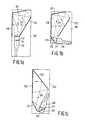
- Fig. 4a shows a part of a first example of the prism plate.
- This plate may be thought to comprise an imaginary plane-parallel plate 833, on both sides of which triangular light-refracting elements 834 and 835 are arranged so that an element 834, or a portion thereof, at the rear, an opposite portion of an element 835 at the front, and the intermediate portion of the plane-parallel plate 833 together form a truncated prism.
- This prism plate may be regarded as an array of identical and identically oriented prisms. Some of these prisms are indicated by means of broken lines.
- the prisms are characterized by the angles ⁇ and ⁇ between the refracting surfaces at the rear and at the front respectively and the plane of the imaginary plane-parallel plate, the sum of ⁇ and ⁇ , referred to as the apex angle ⁇ , and by the angle ⁇ between the third face of a prism and the normal to the prism plate.
- the prisms are oriented in such a way that light which is incident parallel to the principal axis of the light beam is subject to a minimal deviation. This means that the angle of incidence 0 ⁇ i on the rear facet of such an element 834 is equal to the exit angle 0 ⁇ u at which the light emerges from the plane front facet of an element 835.
- angles ⁇ , ⁇ , ⁇ and ⁇ and their mutual relationships are dictated by the required refraction and the value of the refractive index of the material.
- the refractive index of the material of the prism plate is 1.5, and if a minimum deviation is required for light which is incident parallel to the principal axis, the apex angle ⁇ should be 52° and the angles ⁇ and ⁇ should be 11° and 41° respectively.
- An optimum adaptation of the prisms is then obtained when the angle ⁇ is 15°.
- Fig. 4b shows an example of the prism plate in which the subbeam issuing from eachp rism appears to intersect the optical axis of the projection screen in the same point behind the plate.
- the angles of each prism are selected so as to obtain a minimal deviation for each subbeam.
- Fig. 4b a distinction can be made between the parts A, B and C, which correspond to the centre of the plate (B) and the two extremes (A and C). These indications are also given in Fig. 3 for the purpose of orientation.
- the angles between the subbeams and the normal to the prism plate vary from 14° at A to 42° at C when the angle between the principal axis of the beam and the normal to the plane of the prism plate is 30°.
- the angle ⁇ between the facets at the rear of the prism plate and the plane of the prism plate should be 27° at A, 11° in the centre (B), and -6° at C.
- the angle ⁇ should vary from 25° via 41° to 52°.
- a rear-projection screen generally comprises a separate Fresnel lens by means of which the pupil of the projection lens is imaged in the viewing space.
- this Fresnel lens can be integrated in the prism plate by adapting the angles of refraction of each prism to the desired direction of a Fresnel facet at this location.
- Fig. 4c shows an example of a prism plate on which a Fresnel term is superimposed, so that no separate Fresnel lens for the vertical direction is required in the remaining part of the rear-projection screen.
- Characteristic of this plate is that each subbeam is refracted by the corresponding prism in the prism plate towards the same point on the optical axis of the projection screen, which point is situated in front of the screen in the viewing space, for example at a distance of 2.5 m.
- the angle ⁇ varies from -6° at A via 11° at B to 19° at C and the angle ⁇ varies from 17° via 41° to 52°.
- the point where the subbeams intersect the optical axis of the screen may be selected to be situated at any desired distance from the screen, if desired at infinity by adapting the angles of refraction of the prisms.
- the rear-projection screen comprises elements which disperse the light in the viewing space.
- These elements may be cylindrical lenses arranged in the projection plate.
- Horizontally disposed cylindrical lenses for light dispersion in a vertical direction may be integrated in the prism plate by the use of convex instead of plan prism facets at one side of the plate. This is illustrated in Fig. 5, which shows a part of a prism plate in which such planoconvex cylindrical lenses 936 are integrated in the facets 934 at the rear of the prism plate.
- the radius R of the cylindrical lenses should be approximately 1.4 times the pitch S of the prism plate.
- the angle between the incident light and the normal to the prism plate should be limited to approximately 35° at the most. This means that for the dimensions of the screen and the projection distance as assumed in the above examples the angle ⁇ between the principal axis of the light beam and the normal to the prism plate should be limited to approximately 20° at the most.
Landscapes
- Physics & Mathematics (AREA)
- General Physics & Mathematics (AREA)
- Engineering & Computer Science (AREA)
- Multimedia (AREA)
- Signal Processing (AREA)
- Transforming Electric Information Into Light Information (AREA)
- Projection Apparatus (AREA)
- Overhead Projectors And Projection Screens (AREA)
- Optical Elements Other Than Lenses (AREA)
Applications Claiming Priority (2)
| Application Number | Priority Date | Filing Date | Title |
|---|---|---|---|
| NL8600684 | 1986-03-18 | ||
| NL8600684A NL8600684A (nl) | 1986-03-18 | 1986-03-18 | Kompakt doorzichtprojektiesysteem met scheef invallende lichtbundel. |
Publications (1)
| Publication Number | Publication Date |
|---|---|
| EP0240045A1 true EP0240045A1 (de) | 1987-10-07 |
Family
ID=19847730
Family Applications (1)
| Application Number | Title | Priority Date | Filing Date |
|---|---|---|---|
| EP87200338A Withdrawn EP0240045A1 (de) | 1986-03-18 | 1987-02-26 | Kompaktes Durchsichtprotektionssystem mit schief einfallendem Lichtbündel |
Country Status (5)
| Country | Link |
|---|---|
| US (1) | US4963016A (de) |
| EP (1) | EP0240045A1 (de) |
| JP (1) | JPS62226778A (de) |
| DK (1) | DK129287A (de) |
| NL (1) | NL8600684A (de) |
Cited By (4)
| Publication number | Priority date | Publication date | Assignee | Title |
|---|---|---|---|---|
| EP0488590A1 (de) * | 1990-11-30 | 1992-06-03 | THORN EMI plc | Anzeigevorrichtung |
| WO2000003271A3 (en) * | 1998-07-09 | 2000-03-30 | Svyatoslav Ivanovich Arsenich | Projection system |
| US6761459B1 (en) | 1999-07-08 | 2004-07-13 | Svyatoslav Ivanovich Arsenich | Projection system |
| GB2408590A (en) * | 2003-11-28 | 2005-06-01 | Hitachi Ltd | Rear projection type image display device |
Families Citing this family (17)
| Publication number | Priority date | Publication date | Assignee | Title |
|---|---|---|---|---|
| US5208620A (en) * | 1988-10-04 | 1993-05-04 | Canon Kabushiki Kaisha | Display apparatus |
| JPH03241983A (ja) * | 1990-02-20 | 1991-10-29 | Canon Inc | 背面投写型受像機 |
| US5442484A (en) * | 1992-01-06 | 1995-08-15 | Mitsubishi Denki Kabushiki Kaisha | Retro-focus type lens and projection-type display apparatus |
| US5808811A (en) * | 1995-11-08 | 1998-09-15 | Olympus Optical Co., Ltd. | Zoom lens system |
| US5838403A (en) * | 1996-02-14 | 1998-11-17 | Physical Optics Corporation | Liquid crystal display system with internally reflecting waveguide for backlighting and non-Lambertian diffusing |
| US6072551A (en) * | 1996-02-14 | 2000-06-06 | Physical Optics Corporation | Backlight apparatus for illuminating a display with controlled light output characteristics |
| US5975703A (en) | 1996-09-30 | 1999-11-02 | Digital Optics International | Image projection system |
| US5791754A (en) * | 1997-01-14 | 1998-08-11 | International Business Machines Corporation | Compact desktop projection display using three mirrors |
| US6728032B2 (en) * | 2001-10-17 | 2004-04-27 | Infocus Corporation | Rear projection display system |
| JP2004077535A (ja) * | 2002-08-09 | 2004-03-11 | Dainippon Printing Co Ltd | フレネルレンズシート |
| JP4411030B2 (ja) * | 2003-07-22 | 2010-02-10 | キヤノン株式会社 | 投射型表示装置 |
| US7095558B2 (en) * | 2003-09-01 | 2006-08-22 | Hitachi, Ltd. | Image display device, rear projection type screen used in image display device, Fresnel lens sheet, and method of making Fresnel lens sheet |
| US20070008498A1 (en) * | 2005-07-11 | 2007-01-11 | Shohei Matsuoka | Projection display device |
| JP2007183302A (ja) * | 2005-12-29 | 2007-07-19 | Sony Corp | リアプロジェクションディスプレイ装置 |
| US8348489B2 (en) | 2008-01-30 | 2013-01-08 | Qualcomm Mems Technologies, Inc. | Thin illumination system |
| US8721149B2 (en) | 2008-01-30 | 2014-05-13 | Qualcomm Mems Technologies, Inc. | Illumination device having a tapered light guide |
| JP6701681B2 (ja) * | 2015-11-16 | 2020-05-27 | セイコーエプソン株式会社 | 照明装置及びプロジェクター |
Citations (1)
| Publication number | Priority date | Publication date | Assignee | Title |
|---|---|---|---|---|
| US4482206A (en) * | 1983-04-21 | 1984-11-13 | Rca Corporation | Rear projection television screen having a multi-surface Fresnel lens |
Family Cites Families (12)
| Publication number | Priority date | Publication date | Assignee | Title |
|---|---|---|---|---|
| US3580661A (en) * | 1969-04-10 | 1971-05-25 | Bell & Howell Co | Rear projection viewing screen for close viewing |
| US3848980A (en) * | 1971-08-24 | 1974-11-19 | Polaroid Corp | Projector apparatus and system employing unique screen |
| US4173399A (en) * | 1976-09-13 | 1979-11-06 | Izon Corporation | Compact optical viewer for microfiche or cassette |
| JPS5552417Y2 (de) * | 1976-11-18 | 1980-12-05 | ||
| DE2804704A1 (de) * | 1978-02-03 | 1979-08-09 | Soeding Tv Gmbh & Co Bild & To | Projektionseinrichtung |
| JPS57195237A (en) * | 1981-05-27 | 1982-11-30 | Mitsubishi Rayon Co Ltd | Fresnel lens for screen |
| JPS58153924A (ja) * | 1982-03-10 | 1983-09-13 | Hitachi Ltd | 投写用スクリン |
| JPS58197969A (ja) * | 1982-05-14 | 1983-11-17 | Hitachi Ltd | 背面投写形プロジエクシヨンテレビ |
| JPS599649A (ja) * | 1982-07-09 | 1984-01-19 | Dainippon Printing Co Ltd | 透過型投影スクリ−ン |
| US4512631A (en) * | 1983-04-21 | 1985-04-23 | Rca Corporation | Rear projection television screen incorporating a prism lens |
| JPS59173023U (ja) * | 1983-05-09 | 1984-11-19 | パイオニア株式会社 | 投写形テレビジヨン用レンズ装置 |
| JPS61208041A (ja) * | 1985-03-11 | 1986-09-16 | Mitsubishi Rayon Co Ltd | 背面投影スクリ−ン |
-
1986
- 1986-03-18 NL NL8600684A patent/NL8600684A/nl not_active Application Discontinuation
- 1986-08-18 US US06/880,974 patent/US4963016A/en not_active Expired - Fee Related
-
1987
- 1987-02-26 EP EP87200338A patent/EP0240045A1/de not_active Withdrawn
- 1987-03-13 DK DK129287A patent/DK129287A/da not_active Application Discontinuation
- 1987-03-18 JP JP62061388A patent/JPS62226778A/ja active Pending
Patent Citations (1)
| Publication number | Priority date | Publication date | Assignee | Title |
|---|---|---|---|---|
| US4482206A (en) * | 1983-04-21 | 1984-11-13 | Rca Corporation | Rear projection television screen having a multi-surface Fresnel lens |
Non-Patent Citations (6)
| Title |
|---|
| PATENT ABSTRACTS OF JAPAN, vol. 6, no. 200 (E-135)[1078], 9th October 1982; & JP-A-57 109 481 (TOKYO SHIBAURA DENKI K.K.) 07-07-1982 * |
| PATENT ABSTRACTS OF JAPAN, vol. 7, no. 42 (P-177)[1187], 19th February 1983; & JP-A-57 195 237 (MITSUBISHI RAYON K.K.) 30-11-1982 * |
| PATENT ABSTRACTS OF JAPAN, vol. 8, no. 105 (P-274)[1542], 17th May 1984; & JP-A-59 015 925 (MITSUBISHI RAYON K.K.) 27th January 1984 * |
| PATENT ABSTRACTS OF JAPAN, vol. 8, no. 265 (P-318)[1702], 5th December 1984; & JP-A-59 133 533 (DAINIPPON INSATSU K.K.) 31-07-1984 * |
| PATENT ABSTRACTS OF JAPAN, vol. 8, no. 39 (E-228)[1476], 21st February 1984; & JP-A-58 197 969 (HITACHI SEISAKUSHO K.K.) 17th November 1983 * |
| PATENT ABSTRACTS OF JAPAN, vol. 8, no. 97 (P-272)[1534], 8th May 1984; & JP-A-59 009 649 (DAINIPPON INSATSU K.K.) 19-01-1984 * |
Cited By (8)
| Publication number | Priority date | Publication date | Assignee | Title |
|---|---|---|---|---|
| EP0488590A1 (de) * | 1990-11-30 | 1992-06-03 | THORN EMI plc | Anzeigevorrichtung |
| US5184238A (en) * | 1990-11-30 | 1993-02-02 | Thorn Emi Plc | Apparatus for projecting light onto a surface having reflector means for improving the brightness of the image |
| WO2000003271A3 (en) * | 1998-07-09 | 2000-03-30 | Svyatoslav Ivanovich Arsenich | Projection system |
| US6761459B1 (en) | 1999-07-08 | 2004-07-13 | Svyatoslav Ivanovich Arsenich | Projection system |
| GB2408590A (en) * | 2003-11-28 | 2005-06-01 | Hitachi Ltd | Rear projection type image display device |
| GB2408590B (en) * | 2003-11-28 | 2006-11-22 | Hitachi Ltd | Rear projection type image display device |
| US7244030B2 (en) | 2003-11-28 | 2007-07-17 | Hitachi, Ltd. | Rear projection type image display device |
| US7342724B2 (en) | 2003-11-28 | 2008-03-11 | Hitachi, Ltd. | Rear projection type image display device |
Also Published As
| Publication number | Publication date |
|---|---|
| DK129287D0 (da) | 1987-03-13 |
| US4963016A (en) | 1990-10-16 |
| DK129287A (da) | 1987-09-19 |
| JPS62226778A (ja) | 1987-10-05 |
| NL8600684A (nl) | 1987-10-16 |
Similar Documents
| Publication | Publication Date | Title |
|---|---|---|
| US4963016A (en) | Compact rear-projection system with obliquely incident light beam | |
| US4708435A (en) | Rear projection screen | |
| US4767186A (en) | Front projection screen with rear light concentrating lens array | |
| US6728032B2 (en) | Rear projection display system | |
| KR940006725B1 (ko) | 배면 투사 스크린 | |
| US6995907B2 (en) | Diffusion sheet for use in transmission-type screen and transmission-type screen | |
| US4512631A (en) | Rear projection television screen incorporating a prism lens | |
| US4762393A (en) | Rear projection screen and rear projection system provided with such a screen | |
| EP0511721A2 (de) | Auflichtprojektionsschirm mit Linsenraster zur Konzentration des reflektierten Lichtes | |
| US5100222A (en) | Screen and image display apparatus | |
| US6157491A (en) | Lenticular lens sheet | |
| CN1009133B (zh) | 背面投影系统 | |
| JPH083603B2 (ja) | リアプロジェクションスクリーン | |
| AU2001251345A1 (en) | Planar optical waveguides for optical panel having gradient refractive index core | |
| EP0822443B1 (de) | Durchlicht-Projektionsschirm | |
| KR100454725B1 (ko) | 투사형디스플레이장치 | |
| JPS59205878A (ja) | 背面投射式テレビジョン表示装置 | |
| US6900945B2 (en) | Lenticular lens sheet | |
| KR100525622B1 (ko) | 광학적 보정 기능을 갖는 홀로그래픽 스크린이 구비된투사형 텔레비전 | |
| JPH04195030A (ja) | プロジェクタ | |
| US5264941A (en) | Large screen display apparatus utilizing a transparent plate to display an image over an entire surface of a diffusing surface | |
| US5796446A (en) | Television receiver or video monitor of the back-projection type | |
| JPH1138510A (ja) | プロジェクタースクリーン | |
| JP3002477B2 (ja) | 透過型スクリーン | |
| US5142373A (en) | Rear projection television set having improved contrast |
Legal Events
| Date | Code | Title | Description |
|---|---|---|---|
| PUAI | Public reference made under article 153(3) epc to a published international application that has entered the european phase |
Free format text: ORIGINAL CODE: 0009012 |
|
| AK | Designated contracting states |
Kind code of ref document: A1 Designated state(s): DE FR GB |
|
| 17P | Request for examination filed |
Effective date: 19880402 |
|
| 17Q | First examination report despatched |
Effective date: 19900912 |
|
| STAA | Information on the status of an ep patent application or granted ep patent |
Free format text: STATUS: THE APPLICATION IS DEEMED TO BE WITHDRAWN |
|
| 18D | Application deemed to be withdrawn |
Effective date: 19910123 |
|
| RIN1 | Information on inventor provided before grant (corrected) |
Inventor name: BOUWHUIS, GIJSBERTUS Inventor name: HEIJNEMANS, WERNER ADRIANUS LAMBERTUS |