EP0240002B1 - Laseraufzeichnungsvorrichtung - Google Patents
Laseraufzeichnungsvorrichtung Download PDFInfo
- Publication number
- EP0240002B1 EP0240002B1 EP87104791A EP87104791A EP0240002B1 EP 0240002 B1 EP0240002 B1 EP 0240002B1 EP 87104791 A EP87104791 A EP 87104791A EP 87104791 A EP87104791 A EP 87104791A EP 0240002 B1 EP0240002 B1 EP 0240002B1
- Authority
- EP
- European Patent Office
- Prior art keywords
- laser beams
- image
- laser
- modulator
- optical
- Prior art date
- Legal status (The legal status is an assumption and is not a legal conclusion. Google has not performed a legal analysis and makes no representation as to the accuracy of the status listed.)
- Expired - Lifetime
Links
Images


Classifications
-
- H—ELECTRICITY
- H04—ELECTRIC COMMUNICATION TECHNIQUE
- H04N—PICTORIAL COMMUNICATION, e.g. TELEVISION
- H04N1/00—Scanning, transmission or reproduction of documents or the like, e.g. facsimile transmission; Details thereof
- H04N1/04—Scanning arrangements, i.e. arrangements for the displacement of active reading or reproducing elements relative to the original or reproducing medium, or vice versa
- H04N1/19—Scanning arrangements, i.e. arrangements for the displacement of active reading or reproducing elements relative to the original or reproducing medium, or vice versa using multi-element arrays
- H04N1/191—Scanning arrangements, i.e. arrangements for the displacement of active reading or reproducing elements relative to the original or reproducing medium, or vice versa using multi-element arrays the array comprising a one-dimensional [1D] array
- H04N1/1911—Simultaneously or substantially simultaneously scanning picture elements on more than one main scanning line, e.g. scanning in swaths
-
- H—ELECTRICITY
- H04—ELECTRIC COMMUNICATION TECHNIQUE
- H04N—PICTORIAL COMMUNICATION, e.g. TELEVISION
- H04N1/00—Scanning, transmission or reproduction of documents or the like, e.g. facsimile transmission; Details thereof
- H04N1/04—Scanning arrangements, i.e. arrangements for the displacement of active reading or reproducing elements relative to the original or reproducing medium, or vice versa
- H04N1/06—Scanning arrangements, i.e. arrangements for the displacement of active reading or reproducing elements relative to the original or reproducing medium, or vice versa using cylindrical picture-bearing surfaces, i.e. scanning a main-scanning line substantially perpendicular to the axis and lying in a curved cylindrical surface
Definitions
- the present invention relates to a laser exposure system with the features of the first part of claim 1.
- the laser exposure apparatus as known from GB-A-2 156 624 is advantageous in that the laser exposure is effected by adjusting the pitches of beams forming images in optical dots on the screen. A constant beam pitch regardless of any varying deviations occurring in between the image-forming plane in the optical system and the recording plane is not ensured.
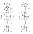
- a source of laser 1 a beam expander 3, a beam splitter 4, a beam-shaping plate 5a, an aperture 6, a multi-channel optical modulator 7, a plate having a slit 8 for diffraction, reflecting mirrors 9a and 9b, and an image-forming optical system 10.
- the beam expander 3 includes a pair of lenses 3a, 3b, which are to expand the diameter of the laser beams B1 emitted from the source 1.
- the beam-shaping plate 5a is to take out a central portion of the laser beams B2 expanded by the expander 3 so as to obtain a relatively constant distribution of optical intensity.
- As the beam-shaping plate another type of beam-shaping plate 5b shown in Figure 1(B) can be used.
- This beam-shaping plate 5b is placed between the beam splitter 4 and the optical modulator 7 and which has several apertures 6b which are open in series in correspondence to the parallel beams B3 divided by the beam splitter 4.
- This beam-shaping plates 5b also shapes the laser beams before they enter the modulator 7 so as to take out that part of laser beams which has a relatively constant optical intensity.
- the beam splitter 4 splits the expanded laser beams B2 into several parallel beams B3.
- This splitter 4 can be provided with a glass plate having parallel surfaces, one of the surfaces having a perfect reflecting coating and the other having a coating which progressively changes the permeability so as to obtain an equal quantity of light throughout the parallel beams B3.
- This type of beam splitter is disclosed in Japanese Patent Publication No. 52-122135.
- the multi-channel optical modulator 7 can be an acousto-optical type, which comprises a plurality of supersonic wave vibrators attached to a single acousto-optical medium.
- the parallel laser beams B3 are caused to impinge on the medium at places corresponding to the respective vibrators, thereby modulating the laser beams B3 individually.
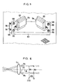
- the beam splitter 4 and multi-channel optical modulator 7 are fixed to a base plate 50 placed on a reference plane (S) by means of a fastener 52.
- the base plate 50 is guided by an adjustable guide 54 in such a manner that it can move in parallel with the laser beams B3 split by the splitter 4.
- the base plate 50 is provided with long holes 56 in which screws 58 are fitted.
- the base plate 50 is fixed on the reference plane (S), and for adjustment they are loosened so as to enable the beam plate to move in parallel with the laser beams.
- Figure 4(B) shows another version, in which the beam splitter 4 is permanently fixed on the reference plane (S), and the multi-channel optical modulator 7 alone is moved for adjustment in parallel with the laser beams B3.
- the slit 8 allows the laser beams modulated by the modulator 7 to pass but prevents those not modulated by it from passing.
- the laser beams B4 passing through the slit 8 are changed in their directions by the first and second mirrors 9a and 9b, so as to be introduced in the image-forming optical system 10.
- the image-forming optical system 10 is a telecentric optical entity which includes two telescopic optical units 11 and 12 telecentrically connected to each other.
- this telecentric entity a plurality of parallel laser beams are reduced in their pitches so as to form an image 14 having a desired width on the screen (F).
- Figure 2 shows a diagrammatic view showing the optical system 10: There are provided first and second lens L1 and L2 in the first telescopic optical unit 11.
- first and second lens L1 and L2 in the first telescopic optical unit 11.
- the parallel laser beams B4 from the beam shaping plate 5b situated at the forward focal position F1 of the first lens L1 are radiated from the second lens L2 as the same number of traces B5, which form an image 13 at the backward focal position F23 of the second lens L2, wherein the image 13 has beam pitches reduced at the ratio M1.
- the second telescopic optical unit 12 also has first and second lenses L3 and L4, which equally constitutes a telecentric optical entity.
- the parallel laser beams B5 from the image 13 formed at the forward focal position (F) of the lens L3 is radiated as the same number of trace B6 from the second lens L4 so as to form an image 14 whose beam pitches are also reduced as desired.
- the second telescopic optical unit 12 includes a zoom lens L5 whereby the beam pitches of the image 14 are steplessly adjusted.
- each reducing rate can be relatively small, thereby minimizing a possible abberation. If only one optical unit is used, the reducing rate will be unavoidably large, which is likely to cause a large abberation.
- the reducing rate is steplessly adjustable in the range of 1/150 to 1/300.
- zoom lens L5 is not limited to the second optical unit 12, and it can be used in the first optical unit 11. If there is no need to adjust the reducing rate steplessly it can be omitted as shown in Figure 3.
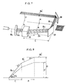
- the advantage of the telecentric image-forming optical entity 10 is that in the case of a possible deviation ⁇ D occurring between the image-forming position (F) or (Q) and the recording position (G) as shown in Figure 6 the dimensions of the images W1 and W2 on the respective positions are practically equal.
- the main optical trace 15 in each laser beam B6 from the second lens L4 is in parallel with the optical axis 16 of the optical unit 12.
- the positional deviation is likely to make the image poor. To avoid this problem it is required to minimize the distance between the positions (F) and (G).
- the laser exposure apparatus of the present invention can compensate the decline of the laser beams to the reference plane (S) in the following manner;
- the distance between a multi-channel modulator 33 and the first mirror 37 is (C)
- the distance between the laser beams B3 flush with the reference plane (S) and the laser beams B4 ⁇ is (A)
- the height of the laser beams B4 ⁇ flush with the recording plane above the reference plane is (D)
- the relationship between the distances (A), (C) and height (D) and the Bragg angles can be approximately expressed by the following equation: wherein the angle ⁇ (radian) is extremely small.
- the distance between the modulator 7 and the first mirror 9a which corresponds to the distance (C) in Figure 7, is adjusted in the following manner, wherein the "distance” means a distance from any selected trace of the laser beams or from an imaginary optical axis of the laser beams B4:
- the Bragg angle ⁇ of the multi-channel optical modulator 7 is measured by means of a suitable measuring device. The measured value is introduced in the equation (2). Thus the values of the distance (C) is determined.
- each screw 58 is loosened so as to enable the base plate 50 to move until the distance between the modulator 7 and the first mirror 9a becomes equal to the calculated value.
- the base plate 50 is again fixed by fastening the screw 58.
- the next step is that the angles of the first and second mirrors 9a, 9b are adjusted. It is adjusted to ensure that the declines of the laser beams from the modulator 7 and those reflecting on the second mirror 9b are complementary for the declines of the laser beams existing between the first and second mirrors 9a and 9b.
- the laser beams reflecting on the second mirror 9b are made in parallel with the reference plane (S) with respect to the sub-scanning direction.
- the row of optical dots output by the image-forming optical system 10 is made in parallel with the reference plane (S).
- the first and second mirrors 9a and 9b are moved for adjustment instead of moving the modulator 7, that is, the two mirrors are synchronously moved in parallel with the laser beams B3, thereby changing the distance (C) between the first mirror 9a and the modulator 7.
- the mirror 9a, 9b are adjustably fixed to the base plate 60 on the reference plane (S) by means of fasteners 62.
- the base plate 60 is guided by a slidable guide 64 in such a manner as to be slidable on the reference plane (S) in parallel with the laser beams B3 split by the beam splitter 4.
- the reference numeral 66 denotes long holes produced in the base plate 60
- the reference numeral 68 denotes screws whereby the base plate 60 is fixed on the reference plane (S).
- the image-forming optical system 10 includes two telescopic optical units 11 and 12 connected but a single mirror or more than two mirrors can be effectively used provided that the system is a telecentric optical entity.
- a plurality of apertures aligned in series can be used, or else a series of apertures can be provided in place between the image-forming optical system and the multi-channel optical modulator. In either case the apertures can make a slit-like long opening all together.
- Another advantage is that even if an error occurs in the Bragg angle of the modulator, and if a decline occurs in the rows of laser beams, the images can be scanned and recorded at accuracy because of the fact that the traces of laser beams are made in parallel with the reference plane (S) with respect to the subscanning direction of the image recording apparatus. In this way the images are scanned and recorded at high fidelity.
- the positions of laser beams output by the laser exposure apparatus are kept constant, thereby fixing the recording basis.
Landscapes
- Engineering & Computer Science (AREA)
- Multimedia (AREA)
- Signal Processing (AREA)
- Facsimile Scanning Arrangements (AREA)
- Mechanical Optical Scanning Systems (AREA)
- Laser Beam Printer (AREA)
Claims (4)
- Vorrichtung zum Bestrahlen mittels eines Lasers und zum Gebrauch beim Abtasten und Aufnehmen von Bildern, wobei die Vorrichtung folgendes umfaßt:
eine Laserlichtquelle (1) zum Aussenden eines Laserstrahls;
einen Laserstrahlaufteiler (4) zum Aufteilen des Laserstrahls von der Lichtquelle in mehrere parallele Laserstrahlspuren;
einen optischen Mehrkanalmodulator (7) zum individuellen Modulieren der Laserstrahlen in Antwort auf Bildsignale;
ein erster und ein zweiter Rückstrahlspiegel (9a, 9b) zum Lenken der durch den Modulator (7) modulierten Laserstrahlen; und
ein abbildendes optisches System (10) zum Projektieren der Laserstrahlen von dem zweiten Rückstrahlspiegel (9b) auf eine Aufnahmeebene,
dadurch gekennzeichnet, daß das abbildende optische System ein erstes Teleskop (11) und zweites Teleskop (12) umfaßt, die optisch koaxial so angeordnet sind, daß die Position des hinteren Brennpunkts (F₂₃) der Ausgangslinse (L₂) des ersten Teleskopes (11) im wesentlichen mit der Position des vorderen Brennpunkts (F₂₃) der Eingangslinse (L₃) des zweiten Teleskopes (12) zusammenfällt. - Vorrichtung nach Anspruch 1, dadurch gekennzeichnet, daß das abbildende System (10) eine Zoomlinse (L₅) enthält.
- Vorrichtung nach Anspruch 1 oder 2, dadurch gekennzeichnet, daß der optische Mehrkanalmodulator (7) in der Richtung einstellbar ist, in welcher die darin empfangenen Laserstrahlen fortschreiten.
- Vorrichtung nach einem der vorangegangenen Ansprüche, dadurch gekennzeichnet, daß der Abstand zwischen dem Modulator (7) und dem ersten Spiegel (9a) variable ist, und daß der erste und zweite Spiegel (9a, 9b) hinsichtlich ihrer Winkel zu einer Referenzebene einstellbar sind.
Applications Claiming Priority (4)
| Application Number | Priority Date | Filing Date | Title |
|---|---|---|---|
| JP76157/86 | 1986-04-02 | ||
| JP61076157A JPS62232611A (ja) | 1986-04-02 | 1986-04-02 | 画像走査記録装置のレ−ザ露光装置 |
| JP303539/86 | 1986-12-18 | ||
| JP30353986A JPS63155020A (ja) | 1986-12-18 | 1986-12-18 | 画像走査記録装置のレ−ザ露光方法 |
Publications (3)
| Publication Number | Publication Date |
|---|---|
| EP0240002A2 EP0240002A2 (de) | 1987-10-07 |
| EP0240002A3 EP0240002A3 (en) | 1989-05-31 |
| EP0240002B1 true EP0240002B1 (de) | 1993-08-11 |
Family
ID=26417308
Family Applications (1)
| Application Number | Title | Priority Date | Filing Date |
|---|---|---|---|
| EP87104791A Expired - Lifetime EP0240002B1 (de) | 1986-04-02 | 1987-04-01 | Laseraufzeichnungsvorrichtung |
Country Status (3)
| Country | Link |
|---|---|
| US (2) | US4810068A (de) |
| EP (1) | EP0240002B1 (de) |
| DE (1) | DE3786939T2 (de) |
Families Citing this family (18)
| Publication number | Priority date | Publication date | Assignee | Title |
|---|---|---|---|---|
| JPS63316817A (ja) * | 1987-06-19 | 1988-12-26 | Dainippon Screen Mfg Co Ltd | 変倍可能なテレセントリック結像光学系 |
| US4884857A (en) * | 1987-11-09 | 1989-12-05 | International Business Machines Corporation | Scanner for use in multiple spot laser electrophotographic printer |
| US5048936A (en) * | 1987-12-29 | 1991-09-17 | Fuji Photo Film Co., Ltd. | Light beam deflector |
| JPH01287622A (ja) * | 1988-05-16 | 1989-11-20 | Think Lab Kk | 光ビーム分割器 |
| US5225924A (en) * | 1989-04-07 | 1993-07-06 | Dainippon Screen Mfg. Co., Ltd. | Optical beam scanning system |
| GB8916133D0 (en) * | 1989-07-14 | 1989-08-31 | Raychem Ltd | Laser machining |
| JP2717035B2 (ja) * | 1991-07-15 | 1998-02-18 | 大日本スクリーン製造株式会社 | マルチビーム走査記録装置 |
| US5635976A (en) * | 1991-07-17 | 1997-06-03 | Micronic Laser Systems Ab | Method and apparatus for the production of a structure by focused laser radiation on a photosensitively coated substrate |
| JPH05242521A (ja) * | 1992-02-27 | 1993-09-21 | Pioneer Electron Corp | 光ディスクプレーヤ |
| JP2782699B2 (ja) * | 1992-03-16 | 1998-08-06 | ローム株式会社 | 光源ユニット |
| US5309178A (en) * | 1992-05-12 | 1994-05-03 | Optrotech Ltd. | Laser marking apparatus including an acoustic modulator |
| US5526182A (en) * | 1993-02-17 | 1996-06-11 | Vixel Corporation | Multiple beam optical memory system |
| WO1995005944A1 (en) * | 1993-08-24 | 1995-03-02 | Micracor, Inc. | A printer and a print engine therefor |
| US5512949A (en) * | 1993-12-29 | 1996-04-30 | Xerox Corporation | Multiple beam raster output scanner optical system having telecentric chief exit rays |
| IL115864A (en) * | 1995-11-02 | 1999-05-09 | Orbotech Ltd | Method and apparatus for delivering laser energy to an object |
| US6181472B1 (en) | 1998-06-10 | 2001-01-30 | Robotic Vision Systems, Inc. | Method and system for imaging an object with a plurality of optical beams |
| DE10062683A1 (de) | 2000-12-15 | 2002-06-20 | Heidelberger Druckmasch Ag | Mehrstrahl-Abtastvorrichtung |
| US10860851B2 (en) * | 2019-03-05 | 2020-12-08 | Htc Corporation | Head mounted display apparatus and eye-tracking apparatus thereof |
Family Cites Families (6)
| Publication number | Priority date | Publication date | Assignee | Title |
|---|---|---|---|---|
| US3195405A (en) * | 1962-12-07 | 1965-07-20 | Thompson Ramo Wooldridge Inc | Optical attenuator |
| GB1523033A (en) * | 1976-03-03 | 1978-08-31 | Crosfield Electronics Ltd | Image reproducing systems |
| DE2922452C2 (de) * | 1978-06-03 | 1999-11-25 | Canon Kk | Lasereinheit |
| US4413270A (en) * | 1981-03-30 | 1983-11-01 | Xerox Corporation | Multigate light valve for electro-optic line printers having non-telecentric imaging systems |
| US4459690A (en) * | 1981-07-30 | 1984-07-10 | Rca Corporation | Multi-beam optical record and playback apparatus having an improved beam splitter |
| US4617578A (en) * | 1984-02-15 | 1986-10-14 | Dainippon Screen Mfg. Co., Ltd. | Multi-beam zoom and focusing lens scan pitch-adjusting recorder |
-
1987
- 1987-04-01 US US07/033,582 patent/US4810068A/en not_active Expired - Fee Related
- 1987-04-01 DE DE87104791T patent/DE3786939T2/de not_active Expired - Fee Related
- 1987-04-01 EP EP87104791A patent/EP0240002B1/de not_active Expired - Lifetime
-
1988
- 1988-08-03 US US07/227,738 patent/US4867542A/en not_active Expired - Fee Related
Also Published As
| Publication number | Publication date |
|---|---|
| DE3786939D1 (de) | 1993-09-16 |
| EP0240002A2 (de) | 1987-10-07 |
| US4867542A (en) | 1989-09-19 |
| US4810068A (en) | 1989-03-07 |
| DE3786939T2 (de) | 1994-03-17 |
| EP0240002A3 (en) | 1989-05-31 |
Similar Documents
| Publication | Publication Date | Title |
|---|---|---|
| EP0240002B1 (de) | Laseraufzeichnungsvorrichtung | |
| US4201455A (en) | Laser-operated apparatus for data and signal recording | |
| US4617578A (en) | Multi-beam zoom and focusing lens scan pitch-adjusting recorder | |
| EP0297361B1 (de) | Telezentrisches abbildendes System mit veränderlicher Vergrösserung | |
| JP2002520644A (ja) | 走査器システム | |
| US4661699A (en) | Scanning beam control system and method with bi-directional reference scale | |
| US4651169A (en) | Laser printer for printing a plurality of output-images sizes | |
| US6643049B2 (en) | Compact imaging head and high speed multi-head laser imaging assembly and method | |
| US4931637A (en) | Scanner utilizing a particular light guide | |
| US20090097002A1 (en) | Exposure device | |
| US5099358A (en) | Apparatus for recording image including an afocal optical system | |
| EP0324364B1 (de) | Optisches Gerät mit Laser | |
| US4614864A (en) | Apparatus for detecting defocus | |
| US5191466A (en) | High resolution two-directional optical scanner | |
| US4633272A (en) | Laser printing apparatus having a multiple formatted output | |
| US4385325A (en) | Raster input scanner comprising two CCD arrays | |
| US5140466A (en) | Optical multiplexer | |
| US4641950A (en) | Exposure system | |
| US4578577A (en) | Light beam scanning device | |
| DE69017891T2 (de) | Lichtstrahlstellungssensor für eine lichtabtastvorrichtung. | |
| US4587420A (en) | Light beam scanning device for correcting scanning speed | |
| JP3058929B2 (ja) | ホログラフィック光学素子の評価方法およびその装置 | |
| US5663554A (en) | Weak lens focus adjusting mechanism based upon thickness of scanned material and imagesetter using same | |
| US5818496A (en) | Exposure device of electrophotographic apparatus with optical path position deciding device | |
| JP5105719B2 (ja) | 光学部品の評価装置、評価方法及びそれを用いた光軸調整装置 |
Legal Events
| Date | Code | Title | Description |
|---|---|---|---|
| PUAI | Public reference made under article 153(3) epc to a published international application that has entered the european phase |
Free format text: ORIGINAL CODE: 0009012 |
|
| AK | Designated contracting states |
Kind code of ref document: A2 Designated state(s): DE FR GB |
|
| PUAL | Search report despatched |
Free format text: ORIGINAL CODE: 0009013 |
|
| AK | Designated contracting states |
Kind code of ref document: A3 Designated state(s): DE FR GB |
|
| 17P | Request for examination filed |
Effective date: 19890928 |
|
| 17Q | First examination report despatched |
Effective date: 19920120 |
|
| GRAA | (expected) grant |
Free format text: ORIGINAL CODE: 0009210 |
|
| AK | Designated contracting states |
Kind code of ref document: B1 Designated state(s): DE FR GB |
|
| PG25 | Lapsed in a contracting state [announced via postgrant information from national office to epo] |
Ref country code: FR Effective date: 19930811 |
|
| REF | Corresponds to: |
Ref document number: 3786939 Country of ref document: DE Date of ref document: 19930916 |
|
| EN | Fr: translation not filed | ||
| PLBE | No opposition filed within time limit |
Free format text: ORIGINAL CODE: 0009261 |
|
| STAA | Information on the status of an ep patent application or granted ep patent |
Free format text: STATUS: NO OPPOSITION FILED WITHIN TIME LIMIT |
|
| 26N | No opposition filed | ||
| PGFP | Annual fee paid to national office [announced via postgrant information from national office to epo] |
Ref country code: GB Payment date: 19970324 Year of fee payment: 11 |
|
| PGFP | Annual fee paid to national office [announced via postgrant information from national office to epo] |
Ref country code: DE Payment date: 19970404 Year of fee payment: 11 |
|
| PG25 | Lapsed in a contracting state [announced via postgrant information from national office to epo] |
Ref country code: GB Free format text: LAPSE BECAUSE OF NON-PAYMENT OF DUE FEES Effective date: 19980401 |
|
| GBPC | Gb: european patent ceased through non-payment of renewal fee |
Effective date: 19980401 |
|
| PG25 | Lapsed in a contracting state [announced via postgrant information from national office to epo] |
Ref country code: DE Free format text: LAPSE BECAUSE OF NON-PAYMENT OF DUE FEES Effective date: 19990202 |