EP0239751A2 - Machine automatique pour le développement de film - Google Patents
Machine automatique pour le développement de film Download PDFInfo
- Publication number
- EP0239751A2 EP0239751A2 EP87101676A EP87101676A EP0239751A2 EP 0239751 A2 EP0239751 A2 EP 0239751A2 EP 87101676 A EP87101676 A EP 87101676A EP 87101676 A EP87101676 A EP 87101676A EP 0239751 A2 EP0239751 A2 EP 0239751A2
- Authority
- EP
- European Patent Office
- Prior art keywords
- discharge pipe
- space
- film
- bottom wall
- developing machine
- Prior art date
- Legal status (The legal status is an assumption and is not a legal conclusion. Google has not performed a legal analysis and makes no representation as to the accuracy of the status listed.)
- Granted
Links
Images

Classifications
-
- G—PHYSICS
- G03—PHOTOGRAPHY; CINEMATOGRAPHY; ANALOGOUS TECHNIQUES USING WAVES OTHER THAN OPTICAL WAVES; ELECTROGRAPHY; HOLOGRAPHY
- G03D—APPARATUS FOR PROCESSING EXPOSED PHOTOGRAPHIC MATERIALS; ACCESSORIES THEREFOR
- G03D3/00—Liquid processing apparatus involving immersion; Washing apparatus involving immersion
- G03D3/02—Details of liquid circulation
- G03D3/06—Liquid supply; Liquid circulation outside tanks
Definitions
- This invention relates to an automatic film developing machine for developing an exposed photographic film.
- Conventional automatic developing machines for photographic films have such a structure that a photographic film is caused to pass through a developer-containing tank so as to develop the photographic film.
- a number of rollers are arranged in pairs in the tank. These rollers are rotated so that a film to be developed is pinched between the roller in each pair and is hence conveyed through the tank. Its development has been completed when the film is fed out of the tank.
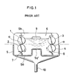
- FIGURE l is a cross-sectional side view of the automatic film developing machine proposed in the above publication.
- Numerals l,2 indicate film feed rollers provided in a pair and letter a indicates their nip.
- Numeral 3,4 indicate film feed rollers provided in a pair in opposition to the film feed rollers l,2.
- the nip of the film feed rollers 3,4 is also designated by a .
- the line connecting both nips a , a i.e., the line shown by a phantom in FIGURE l) is substantially horizontal.
- a catch pan 5 provided underneath the paired film feed rollers l,2,3,4, a bottom wall 5a of the catch pan 5, and a raised central portion 5a ⁇ of the bottom wall 5a of the catch pan 5.
- Numeral 5b indicates both side walls of the catch pan 5. However, one of the side walls 5b is only shown in FIGURE l.
- a space 6 is formed by the film feed rollers l,2,3,4, catch pan 5 and side walls 5b.
- Designated at numerals 7,8 are blades provided respectively in elastic contact with the rollers 2,4 in order to avoid fluid leakage from the space 6.
- Numeral 9 indicates an overflow outlet formed through the side wall 5b.
- Designated at numeral l0 is a return pipe for collecting the developer overflowed to the outside from the space 6 and then recycling same to an unillustrated reservoir.
- the overflow outlet 9 is formed at a height higher than the line which connects the nips a , a to each other.
- the film feed rollers l,2,3,4 are rotated in a direction indicated by arrows and a film to be developed is fed between the film feed rollers l,2 on the left-hand side as viewed in the drawing, the film passes from the film feed rollers l,2 and then through the developer in the space, and is thereafter fed out of the space 6 while being pinched between the film feed rollers 3,4.
- the film can be developed surely without being bent.
- the opposing two pairs of rollers are only required so that the developing machine can itself be constructed in a small size.
- the overflow outlet 9 is formed through the side wall 5b.
- the extra portion of the developer is therefore discharged continuously onto the outer surface of the side wall 5b.
- the outer surface is hence blemished.
- the catch for receiving the developer discharged onto the outer wall must extend out from the side wall 5b, leading to another problem that the overall structure becomes large.
- An object of this invention is therefore to provide an automatic film developing machine which can solve the above-described conventional problems and can avoid the blemish of the outer surface of the side wall and can also reduce the size of the overall structure.
- an automatic film developing machine equipped with a space defined by side walls, a bottom wall and two pairs of film feed rollers, one of said two pairs of film feed rollers being arranged between front end portions of the side walls and the other pair of said film feed rollers being disposed between rear end portions of the side walls, and a means for feeding a film processing solution to the space, which comprises at least one discharge pipe for discharging the film processing solution, said discharge pipe communicating the space to a point outside the space, and the upper end of said discharge pipe being positioned at a desired height higher than the nips of the paired film feed rollers whereas the lower end of said discharge pipe being in communication with a reservoir for the film processing solution.
- the film processing solution When the film processing solution is supplied to the space and the level of the film processing solution exceeds upwardly the upper end of the discharge pipe for the film processing solution, the extra portion of the film processing solution is discharged through the discharge pipe to the reservoir. Accordingly, the level of the film processing solution in the space is maintained at the height of the upper end of the discharge pipe for the film processing solution.
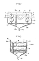
- FIGURES 2 and 3 Designated at numerals l2 and l3 are side walls and a catch pan respectively.
- the first embodiment is identical to the conventional automatic film developing machine depicted in FIGURE l in that these side walls l2 and catch pan l3 form the space 6 together with the film feed rollers l,2,3,4. Different from the side wall 5b shown in FIGURE l, no overflow outlet is however formed through the side wall l2.
- the catch pan l3 defines an opening l4 through a bottom wall l3a thereof.
- Designated at numeral l5 is a discharge pipe inserted in the opening l4. Owing to the insertion in the opening l4, the discharge pipe l5 is secured on the bottom wall l3a and extends into the space 6. The position of the discharge pipe l5 is close to the side wall l2 as shown in FIGURE 3 so that each film is allowed to move freely through the space 6. Numeral l5a indicates the upper end of the discharge pipe l5.
- the height of the upper end l5a is determined in such a way that the upper end l5a is located at a position higher than the level connecting both nips a , a of the paired rollers l - 4 in the first embodiment, the upper end l5a is at a distance L above the level connecting both nips a , a .
- the level of the developer rises in the space 6 and eventually reaches the upper end l5a of the discharge pipe l5. Any developer higher than the height of the upper end l5a is then allowed to flow into the discharge pipe l5 and is discharged from the lower end of the discharge pipe l5 to the return pipe l0. If the diameter of the discharge pipe l5 is suitably chosen in view of the area of the space 6, the charge rate of the developer to the space 6 per unit time, etc., the level of the developer in the space 6 can be always maintained at the same level as the upper end l5a of the discharge pipe l5. When a film to be developed is conveyed by the paired rollers l - 4 in the above state, the film which passes along the level connecting the nips a , a is always caused to move through the developer so as to ensure its development.
- the discharge pipe is fixedly inserted in the opening formed through the bottom wall of the catch pan.
- the discharge pipe may however be fixed on the inner surface of the bottom wall of the catch pan and an opening may then be formed through the bottom wall of the catch pan at a location opposing the discharge pipe.
- the shape of the cross-section of the discharge pipe may be determined at will, for example, may be circular, rectangular, etc.
- the discharge pipe can be provided without obstructing the conveyance of a film even if the clearance between the side wall, which is located on the side of the discharge pipe, and the corresponding edge of the film, when a rectangular shape is chosen in particular.
- a plurality of discharge pipes may also be provided instead of a single discharge pipe.
- the discharge pipe can be provided in contact with either one of the side plate.
- FIGURES 4 and 5 the second embodiment of this invention will be described.
- the same elements of structure as those shown in FIGURE l are indicated by the same reference numerals. Their description is therefore omitted here.
- Designated at numerals l2 and l3 are side walls and a catch pan respectively.
- the second embodiment is identical to the conventional automatic film developing machine depicted in FIGURE l in that these side walls l2 and catch pan l3 form the space 6 together with the film feed rollers l,2,3,4. Different from the side wall 5b shown in FIGURE l, no overflow outlet is however formed through the side wall l2.
- the catch pan l3 defines an opening l4 through a bottom wall l3a thereof.
- Designated at numeral l6 is a discharge pipe inserted in the opening l4. Owing to the insertion in the opening l4, the discharge pipe l6 is secured on the bottom wall l3a and extends into the space 6. The position of the discharge pipe l6 is close to the side wall l2 as shown in FIGURE 5 so that each film is allowed to move freely through the space 6.
- Numeral l6a indicates the upper end of the discharge pipe l6.
- the height of the upper end l6a is determined in such a way that the upper end l6a is located at a position higher than the level connecting both nips a , a of the paired rollers l - 4.
- the upper end l6a is at a distance L above the level connecting both nips a , a .
- Numeral l6b indicates a bore formed through the wall of the discharge pipe l6 at a position close to the bottom wall l3a.
- the level of the developer rises in the space 6 since the developer is allowed to flow out through the bore l6b but the discharge rate of the developer is con siderably lower than the charge rate of the developer.Therefore, the developer eventually reaches the upper end l6a of the discharge pipe l6. Any developer higher than the height of the upper end l6a is then allowed to flow into the discharge pipe l6 and is discharged from the lower end of the discharge pipe l6 to the return pipe l0 along with the developer discharged through the bore l6b.
- the diameter of the discharge pipe l6 is suitably chosen in view of the area of the space 6, the charge rate of the developer to the space 6 per unit time, the size of the bore l6b, etc., the level of the developer in the space 6 can be always maintained at the same level as the upper end l6a of the discharge pipe l6.
- the film which passes along the level connecting the nips a , a is always caused to move through the developer so as to ensure its development. Since the developer near the bottom wall l3a is always discharged through the bore l6b during each developing processing, dust which is floating in the developer is also discharged together with the developer.
- the discharge pipe is fixedly inserted in the opening formed through the bottom wall of the catch pan.
- the discharge pipe may however be fixed on the inner surface of the bottom wall of the catch pan and an opening may then be formed through the bottom wall of the catch pan at a location opposing the discharge pipe.
- the shape of the cross-section of the discharge pipe may be determined at will, for example, may be circular, rectangular, etc.
- the discharge pipe can be provided without obstructing the conveyance of a film even if the clearance between the side wall, which is located on the side of the discharge pipe, and the corresponding edge of the film, when a rectangular shape is chosen in particular.
- a plurality of discharge pipes may also be provided instead of a single discharge pipe.
- the discharge pipe can be provided in contact with either one of the side plate.
- one or more bores may be formed through the wall of the discharge pipe. Where more than one bore is formed, they may be formed at different heights.
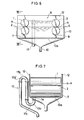
- FIGURES 7 and 7 Designated at numerals l2 and l3 are side walls and a catch pan respectively.
- the third embodiment is identical to the conventional automatic film developing machine depicted in FIGURE l in that these side walls l2 and catch pan l3 form the space 6 together with the film feed rollers l,2,3,4. Different from the side wall 5b shown in FIGURE l, no overflow outlet is however formed through the side wall l2.
- the catch pan l3 defines an opening l4 through a bottom wall l3a thereof.
- Designated at numeral l7 is a discharge pipe connected to the opening l4.
- the discharge pipe l7 has a lower U-pipe l7a and an upper U-pipe l7b.
- the U-pipes l7a,l7b are detachable.
- Numeral l7c indicates a cover provided on the lower wall of a lower end portion of the lower U-pipe l7.
- the cover l7c is provided detachably on the lower U-pipe l7 by way of a suitable means.
- the pipe l7 is provided in such a way that the inner bent portion l7b ⁇ of the upper U-pipe l7b is sufficiently above the respective nips a , a of the film feed rollers l,2,3,4 but is lower than the tops of the film feed rollers l,3.
- the open end of the pipe l7 is positioned above an unillustrated reservoir.
- the developer When the developer is charged into the space 6 from the reservoir by means of an unillustrated pump, the developer flows first of all into the U-shape l7a through the opening l4. When the developer within the pipe l7 has reached the same level as the catch pan l3a, the developer begins to fill the space 6. Thereafter, the levels of the developer in the space 6 and the pipe l7 rise at the same rate.
- the discharge of the developer from the space 6 to the reservoir begins through the opening of the bottom wall l3a of the catch pan l3 and the discharge pipe l7. Since the diameter of the discharge pipe l7 is chosen to have a diameter sufficient to allow the developer to flow out at the same rate as the charge rate of the developer from the reservoir to the space 6, the discharge rate of the developer through the pipe l7 is approximately equal to the charge rate of the developer from the reservoir.
- the level of the developer in the space 6 is always main tained at the same level as the bent portion l7b ⁇ . If the level of the bent portion l7b ⁇ is set at an appropriate height between the tops of the film feed rollers l,3 and the nips a , a of the paired film feed rollers l,2,3,4, the level of the developer is always maintained at a suitable height above the film conveyance line which connects the nips a , a .
- the developer is discharged from the bottom of the space 6, through the opening l4 in the bottom wall l3a of the catch pan l3, and then via the pipe l7.
- Dust is not allowed to remain in the bottom of the space 6 but is discharged out of the space 6 together with the extra portion of the developer. As a consequence, no deleterious effects are given to films.
- a majority of the dust, which has been discharged from the space 6, is allowed to stay in the lower U-pipe l7a of the pipe l7, so that the thus-discharged dust is not recycled back to the space 6. Therefore, the lower U-pipe l7a has a function of dust removal.
- the dust, which has accumulated in the lower U-pipe l7a can be discarded to the outside by either opening the cover l7c or removing the lower U-pipe l7a and cleaning same.
- the catch pan has the flat bottom wall as in the conventional automatic film developing machine shown in FIGURE l. If the entire bottom wall of the catch pan is formed in such a way that it slopes down toward the opening, the dust-discharging function increases apparently to a significant extent. As a further modification, the free end of the discharge pipe may be connected to the return pipe.
Landscapes
- Physics & Mathematics (AREA)
- General Physics & Mathematics (AREA)
- Photographic Processing Devices Using Wet Methods (AREA)
Applications Claiming Priority (4)
| Application Number | Priority Date | Filing Date | Title |
|---|---|---|---|
| JP49033/86U | 1986-04-03 | ||
| JP4903386U JPS62161245U (fr) | 1986-04-03 | 1986-04-03 | |
| JP7704786U JPS62190246U (fr) | 1986-05-23 | 1986-05-23 | |
| JP77047/86U | 1986-05-23 |
Publications (3)
| Publication Number | Publication Date |
|---|---|
| EP0239751A2 true EP0239751A2 (fr) | 1987-10-07 |
| EP0239751A3 EP0239751A3 (en) | 1989-05-31 |
| EP0239751B1 EP0239751B1 (fr) | 1990-12-27 |
Family
ID=26389387
Family Applications (1)
| Application Number | Title | Priority Date | Filing Date |
|---|---|---|---|
| EP87101676A Expired EP0239751B1 (fr) | 1986-04-03 | 1987-02-06 | Machine automatique pour le développement de film |
Country Status (3)
| Country | Link |
|---|---|
| US (1) | US4758857A (fr) |
| EP (1) | EP0239751B1 (fr) |
| DE (1) | DE3766995D1 (fr) |
Cited By (1)
| Publication number | Priority date | Publication date | Assignee | Title |
|---|---|---|---|---|
| WO1989005479A1 (fr) * | 1987-12-07 | 1989-06-15 | Dürr Dental GmbH & Co. KG | Appareil de developpement continu |
Families Citing this family (8)
| Publication number | Priority date | Publication date | Assignee | Title |
|---|---|---|---|---|
| US4987438A (en) * | 1988-06-27 | 1991-01-22 | Konica Corporation | Apparatus for processing light-sensitive material |
| US4994840A (en) * | 1990-03-16 | 1991-02-19 | Eastman Kodak Company | Apparatus for processing photosensitive material |
| US5059997A (en) * | 1990-12-17 | 1991-10-22 | Eastman Kodak Company | Apparatus for processing photosensitive material |
| US5136323A (en) * | 1990-12-28 | 1992-08-04 | Eastman Kodak Company | Apparatus for enhancing heat and mass transfer in a fluid medium |
| US5357307A (en) * | 1992-11-25 | 1994-10-18 | Eastman Kodak Company | Apparatus for processing photosensitive material |
| US5313242A (en) * | 1993-04-27 | 1994-05-17 | Eastman Kodak Company | Thru-wall web processing apparatus |
| US5353083A (en) * | 1993-05-03 | 1994-10-04 | Eastman Kodak Company | Closed solution recirculation/shutoff system for an automatic tray processor |
| US5389994A (en) * | 1993-05-03 | 1995-02-14 | Eastman Kodak Company | Closed solution recirculation/shutoff system for an automatic tray processor |
Family Cites Families (9)
| Publication number | Priority date | Publication date | Assignee | Title |
|---|---|---|---|---|
| US3613547A (en) * | 1969-01-23 | 1971-10-19 | Picker Corp | Film processor |
| US3983934A (en) * | 1975-05-15 | 1976-10-05 | Pako Corporation | Heat exchanger |
| US4023190A (en) * | 1975-06-02 | 1977-05-10 | Sybron Corporation | Film processor |
| US4171716A (en) * | 1978-03-27 | 1979-10-23 | Am International, Inc. | Means for disposing spent chemical solutions from processor |
| US4252429A (en) * | 1979-01-26 | 1981-02-24 | Hope Henry F | Curvilinear, geared transport roller system |
| JPS565544A (en) * | 1979-06-27 | 1981-01-21 | Dainippon Screen Mfg Co Ltd | Developing method and device of film in automatic film developing machine |
| US4324479A (en) * | 1979-11-01 | 1982-04-13 | Sachs Emanuel M | Film processing method and apparatus |
| US4429982A (en) * | 1982-04-08 | 1984-02-07 | Pluribus Products, Inc. | Apparatus and method for processing stabilization photographic paper |
| FR2665556A1 (fr) * | 1990-08-03 | 1992-02-07 | Alcatel Radiotelephone | Dispositif de logement d'une carte a memoire. |
-
1987
- 1987-02-05 US US07/011,340 patent/US4758857A/en not_active Expired - Lifetime
- 1987-02-06 DE DE8787101676T patent/DE3766995D1/de not_active Expired - Fee Related
- 1987-02-06 EP EP87101676A patent/EP0239751B1/fr not_active Expired
Cited By (2)
| Publication number | Priority date | Publication date | Assignee | Title |
|---|---|---|---|---|
| WO1989005479A1 (fr) * | 1987-12-07 | 1989-06-15 | Dürr Dental GmbH & Co. KG | Appareil de developpement continu |
| US5140355A (en) * | 1987-12-07 | 1992-08-18 | Durr Dental Gmbh & Co Kg | Continuous developing apparatus |
Also Published As
| Publication number | Publication date |
|---|---|
| DE3766995D1 (de) | 1991-02-07 |
| US4758857A (en) | 1988-07-19 |
| EP0239751A3 (en) | 1989-05-31 |
| EP0239751B1 (fr) | 1990-12-27 |
Similar Documents
| Publication | Publication Date | Title |
|---|---|---|
| EP0239751A2 (fr) | Machine automatique pour le développement de film | |
| US3067879A (en) | Skim tank | |
| US3091336A (en) | Filter apparatus | |
| US4688917A (en) | Device for wet processing of photographic films | |
| EP0623844A1 (fr) | Appareils de développement automatiques | |
| KR950002537B1 (ko) | 도료 웨이스트 분리 포집장치 | |
| US3988756A (en) | Apparatus for processing webs of photographic material | |
| CN218108504U (zh) | 用于提高色选机物料识别效果的辅助装置 | |
| DE3005471C2 (de) | Einrichtung zur vollständigen Entleerung des Wässerungsbehälters für fotografisches Material mit Umwälzkreislaufpumpe | |
| US5059997A (en) | Apparatus for processing photosensitive material | |
| US3500793A (en) | Developer roller coating means and guide for electrostatic copying machine | |
| DE3432077C2 (de) | Blattfilmverarbeitungsgerät für belichteten Blattfilm | |
| EP0246408B1 (fr) | Dispositif pour collecter des films développés dans une machine de développement, en particulier une machine du genre industriel | |
| EP0947885B1 (fr) | Appareil de développement pour matériau photosensible et structure pour fermer la section de développement de l'appareil | |
| JPH0621953B2 (ja) | 写真感光材料用現像処理装置 | |
| CN211015010U (zh) | 一种自动感光胶片冲洗设备 | |
| JP4359410B2 (ja) | 感光材料処理装置 | |
| CN218502840U (zh) | 一种纸张整理器 | |
| CN1103063C (zh) | 照相洗片机 | |
| US3488116A (en) | Developer mechanism for photocopy machine | |
| CN219290731U (zh) | 一种洗衣龙用绒毛分离装置 | |
| US5899594A (en) | Processing apparatus and method utilizing a tray assembly and a guide path arrangement | |
| JP2590319B2 (ja) | 表面処理装置システム | |
| JPS584097Y2 (ja) | 複写機の現像装置 | |
| JP4081829B2 (ja) | パチンコ島台 |
Legal Events
| Date | Code | Title | Description |
|---|---|---|---|
| PUAI | Public reference made under article 153(3) epc to a published international application that has entered the european phase |
Free format text: ORIGINAL CODE: 0009012 |
|
| AK | Designated contracting states |
Kind code of ref document: A2 Designated state(s): DE FR NL |
|
| PUAL | Search report despatched |
Free format text: ORIGINAL CODE: 0009013 |
|
| AK | Designated contracting states |
Kind code of ref document: A3 Designated state(s): DE FR NL |
|
| 17P | Request for examination filed |
Effective date: 19890613 |
|
| 17Q | First examination report despatched |
Effective date: 19890904 |
|
| GRAA | (expected) grant |
Free format text: ORIGINAL CODE: 0009210 |
|
| AK | Designated contracting states |
Kind code of ref document: B1 Designated state(s): DE FR NL |
|
| REF | Corresponds to: |
Ref document number: 3766995 Country of ref document: DE Date of ref document: 19910207 |
|
| ET | Fr: translation filed | ||
| PLBE | No opposition filed within time limit |
Free format text: ORIGINAL CODE: 0009261 |
|
| STAA | Information on the status of an ep patent application or granted ep patent |
Free format text: STATUS: NO OPPOSITION FILED WITHIN TIME LIMIT |
|
| 26N | No opposition filed | ||
| PGFP | Annual fee paid to national office [announced via postgrant information from national office to epo] |
Ref country code: FR Payment date: 20020221 Year of fee payment: 16 |
|
| PGFP | Annual fee paid to national office [announced via postgrant information from national office to epo] |
Ref country code: NL Payment date: 20020226 Year of fee payment: 16 |
|
| PGFP | Annual fee paid to national office [announced via postgrant information from national office to epo] |
Ref country code: DE Payment date: 20020403 Year of fee payment: 16 |
|
| PG25 | Lapsed in a contracting state [announced via postgrant information from national office to epo] |
Ref country code: NL Free format text: LAPSE BECAUSE OF NON-PAYMENT OF DUE FEES Effective date: 20030901 |
|
| PG25 | Lapsed in a contracting state [announced via postgrant information from national office to epo] |
Ref country code: DE Free format text: LAPSE BECAUSE OF NON-PAYMENT OF DUE FEES Effective date: 20030902 |
|
| PG25 | Lapsed in a contracting state [announced via postgrant information from national office to epo] |
Ref country code: FR Free format text: LAPSE BECAUSE OF NON-PAYMENT OF DUE FEES Effective date: 20031031 |
|
| NLV4 | Nl: lapsed or anulled due to non-payment of the annual fee |
Effective date: 20030901 |
|
| REG | Reference to a national code |
Ref country code: FR Ref legal event code: ST |