EP0239708B1 - Pasteurisierungsvorrichtung für Nahrungsmittel in der Packung - Google Patents
Pasteurisierungsvorrichtung für Nahrungsmittel in der Packung Download PDFInfo
- Publication number
- EP0239708B1 EP0239708B1 EP86420294A EP86420294A EP0239708B1 EP 0239708 B1 EP0239708 B1 EP 0239708B1 EP 86420294 A EP86420294 A EP 86420294A EP 86420294 A EP86420294 A EP 86420294A EP 0239708 B1 EP0239708 B1 EP 0239708B1
- Authority
- EP
- European Patent Office
- Prior art keywords
- pasteurization
- zone
- valves
- tube
- liquid
- Prior art date
- Legal status (The legal status is an assumption and is not a legal conclusion. Google has not performed a legal analysis and makes no representation as to the accuracy of the status listed.)
- Expired - Lifetime
Links
- 238000009928 pasteurization Methods 0.000 title claims description 46
- 239000007788 liquid Substances 0.000 claims description 32
- 238000001816 cooling Methods 0.000 claims description 20
- 238000005507 spraying Methods 0.000 claims description 20
- 238000011144 upstream manufacturing Methods 0.000 claims description 13
- 238000011084 recovery Methods 0.000 claims description 7
- 238000010438 heat treatment Methods 0.000 claims description 5
- 230000005484 gravity Effects 0.000 claims description 2
- 238000012423 maintenance Methods 0.000 claims description 2
- 239000007921 spray Substances 0.000 claims 1
- XLYOFNOQVPJJNP-UHFFFAOYSA-N water Substances O XLYOFNOQVPJJNP-UHFFFAOYSA-N 0.000 description 36
- 239000002826 coolant Substances 0.000 description 4
- 239000000498 cooling water Substances 0.000 description 4
- 238000010586 diagram Methods 0.000 description 4
- 235000013305 food Nutrition 0.000 description 2
- 239000003643 water by type Substances 0.000 description 2
- 238000010793 Steam injection (oil industry) Methods 0.000 description 1
- 238000004519 manufacturing process Methods 0.000 description 1
- 239000002184 metal Substances 0.000 description 1
- 238000005192 partition Methods 0.000 description 1
- 238000004064 recycling Methods 0.000 description 1
- 238000010079 rubber tapping Methods 0.000 description 1
Images

Classifications
-
- A—HUMAN NECESSITIES
- A23—FOODS OR FOODSTUFFS; TREATMENT THEREOF, NOT COVERED BY OTHER CLASSES
- A23B—PRESERVATION OF FOODS, FOODSTUFFS OR NON-ALCOHOLIC BEVERAGES; CHEMICAL RIPENING OF FRUIT OR VEGETABLES
- A23B2/00—Preservation of foods or foodstuffs, in general
- A23B2/003—Control or safety devices for sterilisation or pasteurisation systems
-
- A—HUMAN NECESSITIES
- A23—FOODS OR FOODSTUFFS; TREATMENT THEREOF, NOT COVERED BY OTHER CLASSES
- A23B—PRESERVATION OF FOODS, FOODSTUFFS OR NON-ALCOHOLIC BEVERAGES; CHEMICAL RIPENING OF FRUIT OR VEGETABLES
- A23B2/00—Preservation of foods or foodstuffs, in general
- A23B2/20—Preservation of foods or foodstuffs, in general by heating materials in packages which are progressively transported, continuously or stepwise, through the apparatus
- A23B2/22—Preservation of foods or foodstuffs, in general by heating materials in packages which are progressively transported, continuously or stepwise, through the apparatus with packages on endless chain or band conveyors
Definitions
- the present invention relates to the pasteurization of food products contained in containers, such as for example bottles or metal cans.
- tunnel pasteurizers allowing the pasteurization of food products contained in containers by passing through them a pasteurization tunnel in which are normally carried out successively a heating phase providing a regular rise in temperature during which is preheated, then accelerated heating in a so-called pre-pasteurization zone, then a stage temperature maintenance phase in a so-called pasteurization zone, and finally a cooling phase in a cooling zone
- said pasteurization tunnel being equipped with spraying ramps for the containers with a spraying liquid at a determined temperature for each ramp or group of successive ramps, the temperature of the spraying liquid defining the phase or zone of preheating, prepasteurization, pasteurization, or cooling, and being also equipped with a dispositi f recovery and recycling of the coolant from each boom or group of successive booms at the same coolant temperature.
- the tunnel pasteurizer according to the invention does not have this kind of drawback. It is characterized in that the successive spraying ramps as a whole defining the successive zones of prepasteurization, pasteurization, and possibly at the start of the cooling zone are each supplied with spraying liquid by at least one distributor tube, or the like , common and extending in the direction of advance of the containers, said common distributor tube being provided with valves, operating in all-or-nothing and remotely controllable, making it possible to isolate successive pieces of distributor tube each supplying at least a watering ramp, this distributor tube being able to be supplied with liquid at a pre-pasteurization temperature at its upstream end, as a liquid with a cooling temperature at its downstream end, and as a liquid at a pasteurization temperature on one or more middle pieces, selectable by supply valves, so as to be able to move, in size and position, the pasteurization zone between the prepasteurization and cooling zones, by playing on the closing and opening of said valves.
- the tunnel pasteurizer of the invention is further characterized in that it comprises, for each of the zones supplied by said distributor tube, a reservoir of liquid at watering temperature for the associated zone, and in that that it also includes a device for recovering the coolant from each of said pieces of distributor tube also comprising at least one collector, tubular or the like, common and extending in the direction of advance of the containers, said common collector tube being, in the same way as for the distributor tube, provided with valves operating in all-or-nothing and remotely controllable, making it possible to divide according to the initial watering temperature of the liquids recovered, said collector into portions successive liquids recovered from the ramps of said optional prepasteurization zone, then from said optional pasteurization zone, p after said start of any cooling zone, and finally in that it is equipped with means making it possible to direct the liquid collected respectively in these successive pieces towards said liquid reservoir at watering temperature for the corresponding zone.
- the coolant from each of said ramps relating to said pieces of distributor tube is collected by transverse gutters, or the like, placed under the containers, from each of which it flows by gravity into one of said pieces of said common collecting tube.
- the liquid, collected in the upstream portion of said collecting tube flows through its upstream end towards the reservoir for the prepasteurization zone, the liquid collects in the downstream portion of said collecting tube flows through its downstream end towards the reservoir for said start of the cooling zone, and the middle portion is equipped with means making it possible to direct the liquid collected therein to the reservoir for the pasteurization zone.
- These means are either means of overflow, or conventional means of flow releasable by valve (s).
- the pasteurizer is such that the common distributor tube and the common collecting tube each have the same number of valves, of rank l to n, and is equipped with means making it possible to simultaneously control and in the same way (open or closed) the two valves of the same rank (1, or 2, or ..., or n) on the distributor tube on the one hand and on the collecting tube on the other hand, so that successive portions of the distributor tube have the same relative positions and dimensions as the collecting tube.
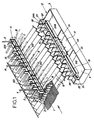
- FIG. 1 there is partially shown the central part of a tunnel pasteurizer according to the invention.
- This pasteurizer and its functional elements have been simplified as much as possible to facilitate understanding, so that the diagram in FIG. 1 is rather a diagram of principle, essential for facilitating understanding, than a more real diagram of practical implementation, such a diagram given below with reference to FIGS. 2 to 4.
- This figure has been designated by the reference 1 the transporter on which the bottles 2 to be pasteurized move in the direction indicated by the arrow, that is to say from left to right in the drawing.
- the pasteurizer is equipped with transverse spraying ramps 3, spraying the bottles 2 with water at a well-determined temperature.
- Each watering ramp 3 is supplied with water from a single central distributor tube 4, arranged along the longitudinal axis of the machine, of square section in the example considered, closed at its two ends and furnished with openings lateral 5 water supply of each ramp.
- the three tanks 7, 11 and 9 are contiguous and located in the same elongated tank 12, separated into three tanks 7, 11, 9 by two transverse partitions 13 and 14.
- each of the tanks 7, 11, 9 is supplied with cold water and / or steam so as to establish and / or maintain the desired temperature therein, in our example 70 ° C., 60 ° C, and 45 ° C.
- the pipes 6, 10 and 8 are each supplied from the reservoir 7, 11, 9 associated with a conventional hydraulic pump.
- the cold water and steam injection devices, as well as the hydraulic pumps, have not been shown in the simplified drawing of FIG. 1.
- each orifice 5 for supplying water to a ramp 3 is separated from the neighboring orifice by a remotely controlled valve 15, such as a solenoid valve.
- a remotely controlled valve 15 such as a solenoid valve.
- the valves 15 have been shown in the form of cofferdam type valves. In the example shown in the drawing, the first three valves, from upstream to downstream, are open, the fourth valve 154 is closed, the following six valves are open, the eleventh valve 1511 is closed, and the twelfth valve is open.
- the length of the three zones can be adjusted by playing on the twelve valves 15. For example, we can open the valve 1511, close the seventh valve 157, open the valve 154 and close the second valve 152, obtaining a large cooling zone 18, a prepasteurization zone 17 moved to the left and slightly smaller, and a pasteurization zone 16 twice as small.
- each gutter Under the conveyor 1, carrying the bottles 2, is installed a series 19 of gutters with a V-section.
- the bottom of each gutter being the vertical of each ramp 3 and in alignment with the corresponding ramp, as seen in the drawing.
- the gutters 9 are therefore transverse and orthogonal to the distributor tube 4, and they are also slightly inclined to the left in the direction of the tank 12 intended to receive the recovered sprinkling water.
- each gutter 19 falls into an elongated collecting tank, which will be called “collecting tube", or collector, of square section and open upwards.
- the collecting tube 20 is fitted with remotely controllable valves 21, with the same function as the valves 15, and furthermore with the same relative position on the collecting tube 20 as the valves 15 on the distributor tube 4.
- the collecting tube 20 therefore has substantially the same length as the distributor tube 4 and substantially the same number of valves dividing it into pieces of the same length.
- the tube 20 is longer, by the value of a piece on each side, than the tube 4, and it is closed, for its central part of the same length as that of the tube 4, by the two end valves 211 and 2114.
- the two additional ends 22 and 23 of the collecting tube 20 open directly into the tank 7 and into the tank 9 respectively through communication openings 24 and 25.
- the right lateral side of the tube 20 is, in its central part between the valves 211 and 2114, slightly lower than the other sides. This height difference allows the water, contained in the tube 20 between two closed valves 215 and 2112, to flow by overflow through a second elongated tank 26 also open. on the top, of height for example equal to the aforementioned reduced lateral height of the tank 12, and open in its center towards the tank 11 following a central opening 27.
- the valves 21 are homologous with the valves 15 not only in relative positions in space, but also in relative opening and closing positions. Consequently, as can be seen in the drawing, the fifth valve 215, homologous to the fourth valve 154 of the tube 4, is closed, the twelfth valve 2112 homologous to the valve 1511 is closed, and all the other valves are open. It will however be noted that the two additional end valves 2111 and 2114 of the tube 20 are open in this case to allow the flow of the recovered liquid towards the end spaces 22 and 23 and therefore towards the tanks 7 and 9.
- the ramps 3 are supplied with water for prepasteurization, pasteurization, and cooling, in accordance with zones 16,17,18, above defined and delimited by valves 154 and 1511.
- the sprinkler water from each ramp 3 is collected under the bottles 2 in the bottom of the corresponding gutter 19. From there, this water flows into the collector 20, respectively into two valves 21 homologous to the two valves 15 attracting the ramp 3 considered.
- the prepasteurization waters relating to the zone 16 flow into the upstream zone of the tube 20 delimited by the valve 215. From there, they flow naturally into the tank 7 through the opening 24.
- the cooling waters relating to the zone 18 flow naturally into the last downstream portion of the tube 20 starting after the valve 2112.
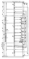
- FIGS. 2,3,4 partially and schematically represent a more real practical example of embodiment of the invention, it being understood that this pasteurizer operates on the same principle as the simplified pasteurizer of FIG. 1.
- the bottles enter the pasteurizer at E and exit from it at S.
- the bottles Before reaching the central zone Z of the pasteurizer, the only one concerned by the invention, the bottles pass, upstream and downstream of this zone respectively, by three successive zones of heating Z1, Z2, Z3, and by three successive zones of cooling Z4, Z5, Z6.
- the operation of these six zones Z1 to Z6 is very conventional and will therefore be recalled here very briefly.
- the zone Z1 is composed of a distributor tube 30 carrying sprinkler booms 31, and of a recovery tank 32 for sprinkling water coming from the booms 31.
- the last cooling zone Z6 comprises, of homologous to zone Z1.
- Each recovery tank has a conventional device 36 for injecting cold water or water vapor as the case may be.
- Each tank 32 and 35 is associated with a hydraulic pump 37 and 38 placed therein. As is well known in the art, the pump 38 of the tank 35 feeds by a pipe 39 the distributor tube 30 of the zone Z1, and conversely the pump 37 of the tank 32 supplies by a tube 40 the distributor 33 of the zone Z6.
- the central zone Z object of the invention, is very similar to that of FIG. 1, and the elements corresponding to those of this figure have been designated therein by the same reference numbers to facilitate understanding.
- the reservoir 7 for prepasteurization water comprises three hydraulic pumps 41,42,43.
- the reservoir 11 has three pumps 44,45,46, and the tank 12 has two hydraulic pumps 47,48.
- Each of these pumps is connected by each a tube 49 comprising a non-return valve 50, to a first intermediate common distributor tube 51. From this longitudinal tube 51 there are two tubes 52 supplying water to the distributor 4 in several places thereof , comprising the upstream and downstream ends, and points spaced by two or three ramps as shown. Furthermore, each tube 52 is provided with a solenoid valve 53, and the common tube 51 is provided with a solenoid valve 54 at each of these tapping and supply points, as seen in the drawing. As seen elsewhere in FIG. 3, each pump such as 45 is associated with a conventional filter 55.
- the zone Z is only divided, for example into a prepasteurization zone followed by a pasteurization zone, the two zones being for example of the same length.
- all the valves of the distributor tube 4 are opened, with the exception of the central valve 15c.
- all the valves of the collecting tube 20 are open, with the exception also of its central valve.
- the electrical supply to the pumps 41 to 46 is started, but not to that of the pumps 47 and 48.
- the valve 54c of the tube 51 which is located just upstream of the pump 44 is closed. All the other valves 54 are left open and 53. It can then be seen that all the ramps 3 located upstream of the valve 15c are supplied from the tank 7 with prepasteurization water, while all the other ramps 3 located downstream from the valve 15c are supplied with pasteurization water at from bin 11.
Landscapes
- Life Sciences & Earth Sciences (AREA)
- Engineering & Computer Science (AREA)
- Wood Science & Technology (AREA)
- Zoology (AREA)
- Chemical & Material Sciences (AREA)
- Food Science & Technology (AREA)
- Polymers & Plastics (AREA)
- Food Preservation Except Freezing, Refrigeration, And Drying (AREA)
Claims (8)
- Pasteurisierungsvorrichtung für Nahrungsmittel in den Packungen (2), indem sie durch einen Pasteurisierungstunnel hindurchgeführt werden, in dem normalerweise aufeinanderfolgend eine Erwärmungsphase, in der ein gleichmäßiger Temperaturanstieg bewirkt wird, im Laufe dessen sich eine Vorheizung vollzieht, dann eine beschleunigte Erwärmung in einer sogenannten Vorpasteurisierungszone, dann eine Phase der Aufrechterhaltung einer Temperaturstufe in einer sogenannten Pasteurisierungszone und schließlich eine Abkühlungsphase in einer Abkühlungszone ablaufen, wobei dieser Pasteurisierungstunnel mit Rohren (3) versehen ist zum Besprühen der Packungen mittels einer Sprühflüssigkeit mit vorbestimmter Temperatur für jedes Rohr oder jede Gruppe aufeinanderfolgender Rohre, wobei die Temperatur der Sprühflüssigkeit die Phase oder Zone der Vorheizung, der Vorpasteurisierung, der Pasteurisierung oder der Abkühlung vorgibt, und darüberhinaus mit einer Vorrichtung zur Wiedergewinnung und Wiederverwendung der Sprühflüssigkeit aus jedem Rohr oder jeder Gruppe von aufeinanderfolgenden Rohren mit gleicher Sprühtemperatur versehen ist,
dadurch gekennzeichnet, daß die aufeinanderfolgenden Rohre (3) zum Besprühen, die in ihrer Gesamtheit die aufeinanderfolgenden Zonen der Vorpasteurisierung, Pasteurisierung und gegebenenfalls des Beginns der Abkühlungszone vorgeben, alle mit Sprühflüssigkeit über wenigstens einen gemeinsamen Rohrverteiler (4) o.dgl. versorgt sind, der sich in der Fortbewegungsrichtung der Packungen erstreckt, wobei dieser gemeinsame Rohrverteiler mit Schiebern (15) versehen ist, die im Auf-Zu-Betrieb arbeiten und fernsteuerbar sind und zwischen aufeinanderfolgenden Schiebern die Trennung von aufeinanderfolgenden Abschnitten des Rohrverteilers ermöglichen, die jeweils wenigstens ein Sprührohr (3) versorgen, wobei dieser Rohrverteiler mit die Vorpasteurisierungstemperatur aufweisender Flüssigkeit an seinem stromaufwärtsseitigen Ende, mit die Abkühltemperatur aufweisender Flüssigkeit an seinem stromabwärtsseitigen Ende und mit die Pasteurisierungstemperatur aufweisender Flüssigkeit an einem oder mehreren mittleren Abschnitten versorgbar ist, die durch Versorgungsschieber (15) auswählbar sind, damit die Pasteurisierungszone (17) zwischen den Zonen der Vorpasteuerisierung (16) und der Abkühlung (18) in Größe und Position durch öffnen und Schließen der genannten Schieber verstellt werden kann. - Pasteurisierungsvorrichtung nach Anspruch 1, dadurch gekennzeichnet, daß sie für jede der durch den genannten gemeinsamen Rohrverteiler versorgten Zonen (16, 17, 18) ein die Sprühtemperatur für die zugeordnete Zone aufweisendes Flüssigkeitsreservoir (7, 11, 9) enthält, und daß sie eine Vorrichtung (19, 20) zur Wiedergewinnung der Sprühflüssigkeit aus jedem der genannten Abschnitte des Rohrverteilers aufweist, die auch wenigstens einen gemeinsamen rohrförmigen o.dgl. Sammler (20) enthält und sich in der Fortbewegungsrichtung der Packungen erstreckt, wobei dieser gemeinsame Sammler in gleicher Weise wie der Rohrverteiler mit Schiebern (21) versehen ist, die im Auf-Zu-Betrieb arbeiten und fernsteuerbar sind sowie das Auftrennen des besagten Sammlers in Abhängigkeit der ursprünglichen Sprühtemperatur der wiedergewonnenen Flüssigkeiten in aufeinanderfolgende Bereiche ermöglichen, von denen jeder einer aus den Rohren jeder Zone wiedergewonnenen Flüssigkeit entspricht, und daß sie mit Mitteln (22 - 27) zum Zuführen der aufgefangenen Flüssigkeit jeweils in diese aufeinanderfolgenden Abschnitte zum besagten Flüssigkeitsreservoir (7, 11, 9) bei einer Sprühtemperatur für die entsprechenden Zone versehen ist.
- Pasteurisierungsvorrichtung nach Anspruch 2, dadurch gekennzeichnet, daß die Sprühflüssigkeit aus jedem der genannten Rohre bezogen auf die genannten Abschnitte des Rohrverteilers durch transversale Rinnen (19) o.dgl. aufgefangen wird, die unter den Packungen (2) angeordnet sind und von jeder derselben durch Schwerkrafteinfluß in einen der genannten Abschnitte des genannten gemeinsamen Rohrsammlers abfließt.
- Pasteurisierungsvorrichtung nach Anspruch 2 oder 3, dadurch gekennzeichnet, daß die in dem stromaufwärtsseitigen Bereich des genannten Sammlers (2) aufgefangene Flüssigkeit über dessen stromaufwärtsseitiges Ende zum Reservoir (7) für die Vorpasteurisierungsphase abfließt, daß die in dem stromabwärtsseitigen Bereich des genannten Sammlers aufgefangene Flüssigkeit über dessen stromabwärtsseitiges Ende zum Reservoir (7) für den genannten Anfang der Abkühlzone abfließt, und daß der mittlere Bereich mit Mitteln (26, 27) zum Leiten der aufgefangenen Flüssigkeit in diesen über das Reservoir (11) für die Pasteurisierungszone versehen ist.
- Pasteurisierungsvorrichtung nach Anspruch 4, dadurch gekennzeichnet, daß die genannten Mittel (26, 27) überlaufmittel sind.
- Pasteurisierungsvorrichtung nach Anspruch 4, dadurch gekennzeichnet, daß die genannten Mittel (26, 27) durch Schieber freigebbare Abfließmittel sind.
- Pasteurisierungsvorrichtung nach einem der Ansprüche 2 bis 6, dadurch gekennzeichnet, daß der genannte gemeinsame Rohrverteiler (4) und der genannte gemeinsame Sammler (20) jeweils dieselbe Anzahl von Schiebern der Rangstufe 1 bis n aufweist, und daß sie mit Mitteln zur simultanen und gleichartigen (auf und zu) Steuerung der beiden Schieber derselben Rangstufe (1, oder 2, oder..., oder n) am Rohrverteiler einerseits und am Sammler andererseits versehen ist, damit die aufeinanderfolgenden Bereiche des Rohrverteilers einerseits und die aufeinanderfolgenden Bereiche des Sammlers andererseits dieselben Positionen und Ausdehnungen relativ zueinander am Rohrverteiler und am Sammler aufweisen.
- Pasteurisierungsvorrichtung nach Anspruch 7, dadurch gekennzeichnet, daß die Zwischenräume zwischen zwei aufeinanderfolgenden Schiebern am Verteiler dieselbe Länge aufweisen, wie die ihnen entsprechenden Intervalle zwischen zwei aufeinanderfolgenden Schiebern derselben Rangstufe am Sammler, so daß die aufeinanderfolgenden Bereiche des Rohrverteilers immer dieselbe Länge aufweisen wie die ihnen entsprechenden Bereiche am Sammler.
Applications Claiming Priority (2)
| Application Number | Priority Date | Filing Date | Title |
|---|---|---|---|
| FR8603613 | 1986-03-04 | ||
| FR8603613A FR2595210B1 (fr) | 1986-03-04 | 1986-03-04 | Dispositif de pasteurisation de produits alimentaires contenus dans des recipients |
Publications (2)
| Publication Number | Publication Date |
|---|---|
| EP0239708A1 EP0239708A1 (de) | 1987-10-07 |
| EP0239708B1 true EP0239708B1 (de) | 1991-04-10 |
Family
ID=9333097
Family Applications (1)
| Application Number | Title | Priority Date | Filing Date |
|---|---|---|---|
| EP86420294A Expired - Lifetime EP0239708B1 (de) | 1986-03-04 | 1986-11-27 | Pasteurisierungsvorrichtung für Nahrungsmittel in der Packung |
Country Status (6)
| Country | Link |
|---|---|
| US (1) | US4704958A (de) |
| EP (1) | EP0239708B1 (de) |
| DE (1) | DE3678714D1 (de) |
| DK (1) | DK161618C (de) |
| ES (1) | ES2021607B3 (de) |
| FR (1) | FR2595210B1 (de) |
Families Citing this family (21)
| Publication number | Priority date | Publication date | Assignee | Title |
|---|---|---|---|---|
| IT1236857B (it) * | 1989-11-27 | 1993-04-22 | Apparecchiatura per il controllo del processo di pastorizzazione. | |
| IL93099A (en) * | 1990-01-18 | 1993-03-15 | Zohar Reuveni Moshav Beit Heru | Pasteurizing machine |
| DE4010921A1 (de) * | 1990-04-04 | 1991-10-10 | Tuchenhagen Otto Gmbh | Verfahren zur erzielung gleichbleibender produktqualitaet und -sicherheit in pasteurisierungsanlgen bei eintritt eines staus und anordung zur ausfuehrung des verfahrens |
| US5280748A (en) * | 1992-02-24 | 1994-01-25 | W. R. Grace & Co.-Conn. | Cook/chill tank |
| NL9300404A (nl) * | 1993-03-05 | 1994-10-03 | Heineken Tech Services | Werkwijze voor het pasteuriseren van in houders opgenomen vloeistof alsmede een tunnelpasteur voor het uitvoeren van een dergelijke werkwijze. |
| DK86294A (da) * | 1994-07-20 | 1996-01-21 | Sander Hansen A S | Fremgangsmåde og apparat til at pasteurisere en fortløbende række af produkter |
| EP0878136B1 (de) | 1997-04-23 | 2004-11-03 | Krones Ag | Vorrichtung zur Flüssigkeitsbeaufschlagung von Gefässen |
| DE19908035B4 (de) * | 1999-02-24 | 2006-03-23 | Khs Maschinen- Und Anlagenbau Ag | Verfahren zum Betreiben einer Pasteurisierungsanlage |
| IT1314425B1 (it) * | 2000-08-09 | 2002-12-13 | Sasib Spa | Apparato di riscaldamento e di controllo della temperatura di processo in un pastorizzatore a tunnel. |
| DE102005028195A1 (de) * | 2005-06-17 | 2006-12-21 | Sander Hansen A/S | Tunnelpasteur |
| US8468936B2 (en) * | 2007-06-27 | 2013-06-25 | Stokely-Van Camp, Inc. | Energy and water conservation in cooling of containers containing heated products |
| EP2058386B1 (de) * | 2007-11-08 | 2009-07-15 | Sidel Holdings & Technology S.A. | Tunnel-Pasteurisierer |
| DE102010020429B4 (de) | 2010-05-12 | 2024-02-22 | Khs Gmbh | Pasteur mit geregelter Spritzmenge |
| DE102012006742A1 (de) * | 2012-04-04 | 2013-10-10 | Khs Gmbh | Pasteurisiervorrichtung |
| DE102012219184A1 (de) * | 2012-10-22 | 2014-05-08 | Krones Aktiengesellschaft | Vorrichtung zur thermischen Behandlung von Produkten mit Reinigung der Prozessflüssigkeit |
| DE102014108798A1 (de) * | 2014-06-24 | 2015-12-24 | Krones Ag | Pasteurisationssystem mit Reinigung der Prozessflüssigkeit |
| AT516673A1 (de) * | 2014-12-22 | 2016-07-15 | Red Bull Gmbh | Verfahren und Vorrichtung zur Behandlung von Lebensmitteln und/oder Behältnissen zur Aufnahme von Lebensmitteln |
| DE102017205551A1 (de) * | 2017-03-31 | 2018-10-04 | Krones Ag | Flaschenbehandlungsmaschine und Verfahren zum Reinigen des Pumpen-/Düsenschutzes der Flaschenbehandlungsmaschine |
| CN110731450A (zh) * | 2019-11-20 | 2020-01-31 | 福建平哥食品有限公司 | 一种用于泡鸭爪生产的巴氏杀菌装置 |
| CN114886074B (zh) * | 2022-06-06 | 2024-06-07 | 肖艳 | 用于食品加工的杀菌系统 |
| DE102023114812A1 (de) * | 2023-06-06 | 2024-12-12 | Krones Aktiengesellschaft | Verfahren zur Regelung einer Transportgeschwindigkeit in einem Pasteur und Vorrichtung zum Ausführen des Verfahrens |
Family Cites Families (13)
| Publication number | Priority date | Publication date | Assignee | Title |
|---|---|---|---|---|
| FR602749A (de) * | 1926-03-25 | |||
| US1004885A (en) * | 1909-12-08 | 1911-10-03 | Charles H Loew | Process of pasteurization. |
| GB377361A (en) * | 1931-05-29 | 1932-07-28 | John Simeon Clayton Marshall | Apparatus for pasteurizing liquids in containers |
| FR1112674A (fr) * | 1951-01-06 | 1956-03-16 | Elfulux | Four à fonctionnement continu et à récupération pour le traitement de matières et objets |
| US3622357A (en) * | 1970-07-20 | 1971-11-23 | Basf Wyandotte Corp | Automatic feed system for treating brewery pasteurizer water |
| US3850089A (en) * | 1970-10-30 | 1974-11-26 | Swift & Co | Food processing system |
| NL7315470A (nl) * | 1973-11-12 | 1975-05-14 | Stork Amsterdam | Werkwijze en inrichting voor het steriliseren of pasteuriseren van produkten verpakt in houders. |
| US4218486A (en) * | 1975-01-28 | 1980-08-19 | W. R. Grace & Co. | Process for packaging, cooling and storing food items |
| US4164590A (en) * | 1976-12-16 | 1979-08-14 | Fmc Corporation | Low liquid volume retort method |
| US4331629A (en) * | 1980-09-15 | 1982-05-25 | Barry-Wehmiller Company | Steam and water conservation system for pasteurizers |
| US4441406A (en) * | 1982-06-14 | 1984-04-10 | Miller Brewing Company | Pasteurization apparatus |
| JPS59118072A (ja) * | 1982-12-25 | 1984-07-07 | Mitsubishi Heavy Ind Ltd | 密封缶詰体の殺菌処理装置 |
| US4606262A (en) * | 1984-07-25 | 1986-08-19 | Campbell Soup Company | Apparatus for heat treating food |
-
1986
- 1986-03-04 FR FR8603613A patent/FR2595210B1/fr not_active Expired
- 1986-11-27 DE DE8686420294T patent/DE3678714D1/de not_active Expired - Fee Related
- 1986-11-27 ES ES86420294T patent/ES2021607B3/es not_active Expired - Lifetime
- 1986-11-27 EP EP86420294A patent/EP0239708B1/de not_active Expired - Lifetime
- 1986-12-02 DK DK580086A patent/DK161618C/da not_active IP Right Cessation
-
1987
- 1987-01-23 US US07/006,377 patent/US4704958A/en not_active Expired - Fee Related
Also Published As
| Publication number | Publication date |
|---|---|
| EP0239708A1 (de) | 1987-10-07 |
| DK580086A (da) | 1987-09-05 |
| FR2595210B1 (fr) | 1988-06-17 |
| DK161618C (da) | 1992-01-27 |
| DK161618B (da) | 1991-07-29 |
| ES2021607B3 (es) | 1991-11-16 |
| DK580086D0 (da) | 1986-12-02 |
| FR2595210A1 (fr) | 1987-09-11 |
| DE3678714D1 (de) | 1991-05-16 |
| US4704958A (en) | 1987-11-10 |
Similar Documents
| Publication | Publication Date | Title |
|---|---|---|
| EP0239708B1 (de) | Pasteurisierungsvorrichtung für Nahrungsmittel in der Packung | |
| EP1151707B1 (de) | Vorrichtung zum Extrahieren einer Substanz mit einem mobilen Teil | |
| EP0710441B1 (de) | Bäckereiofen zum kontinuierlichen Kochen von Back- oder Konditorwaren oder ähnlichen | |
| FR2589332A1 (fr) | Procede et dispositif de pasteurisation de produits alimentaires contenus dans des recipients | |
| CA2357795C (fr) | Machine de remplissage comportant des moyens perfectionnes de nettoyage | |
| EP0516563A1 (de) | Waschverfahren und Desinfektionsverfahren für Schuhe und Vorrichtung zur Durchführung des Verfahrens | |
| FR2479788A1 (fr) | Table de transport pneumatique, notamment pour la manutention de boites a boisson vides | |
| EP0824739A1 (de) | Apparat zur ausgabe von kühlelementen und solche kühlelemente | |
| FR2537845A1 (fr) | Procede et dispositif pour prendre des sucettes glacees dans des poches de congelation d'une machine pour les congeler | |
| FR2547017A1 (fr) | Appareil pour fournir un filet continu d'un liquide cryogenique, notamment d'azote liquide | |
| EP0470922A1 (de) | Automatische Maschinen zur vertikalen Positionierung von Behältern | |
| EP2446746A1 (de) | Installation zur Behandlung von Lebensmittelprodukten mit einer Flüssigkeit | |
| EP1504645B1 (de) | Verfahren zum Verteilen von Dünger oder anderem kornförmigen Material | |
| FR2688299A1 (fr) | Banc frigorifique, avec degivrement a temperature constante, pour produits alimentaires a la piece. | |
| FR2483762A1 (fr) | Machine a cafe avec regulation thermique perfectionnee | |
| FR2537307A1 (fr) | Module separateur de gobelets et distributeur automatique equipe de ce module | |
| WO2006000703A1 (fr) | Dispositif de traitement de produits alimentaires dans un bain de liquide | |
| EP0225220B1 (de) | Waschmaschine mit einem mit mehreren Kammern ausgerüsteten Waschmittelbehälter | |
| EP0233854A1 (de) | Vorrichtung zum Kühlen eines bewegten Metallbandes | |
| FR2651645A1 (fr) | Dispositif pour l'amelioration de la qualite de la vendange par maturation ou surmaturation, en vue de la vinification. | |
| FR2582089A1 (fr) | Dispositif de fabrication de glacons | |
| EP0193684B1 (de) | Vorrichtung zum Teilen einer primären Strömung in mehrere sekundäre Strömungen, wobei die Durchflussmengen vorherbestimmte Bruchteile der primären Durchflussmenge sind | |
| EP0295182B1 (de) | Verfahren zum Kondensieren eines Dampfes, Vorrichtung zur Durchführung sowie eine solche Vorrichtung enthaltender Evaporator | |
| FR2793005A1 (fr) | Procede et appareil de refroidissement en continu d'un produit au moyen d'un fluide cryogenique | |
| FR2500920A1 (fr) | Dispositif pneumatique pour le decollement de la glace des dalles d'evaporation dans un generateur de glaces en plaques ou en feuilles |
Legal Events
| Date | Code | Title | Description |
|---|---|---|---|
| PUAI | Public reference made under article 153(3) epc to a published international application that has entered the european phase |
Free format text: ORIGINAL CODE: 0009012 |
|
| AK | Designated contracting states |
Kind code of ref document: A1 Designated state(s): DE ES GB IT |
|
| 17P | Request for examination filed |
Effective date: 19871120 |
|
| RAP1 | Party data changed (applicant data changed or rights of an application transferred) |
Owner name: SOCIETE GANGLOFF |
|
| 17Q | First examination report despatched |
Effective date: 19900802 |
|
| GRAA | (expected) grant |
Free format text: ORIGINAL CODE: 0009210 |
|
| AK | Designated contracting states |
Kind code of ref document: B1 Designated state(s): DE ES GB IT |
|
| ITF | It: translation for a ep patent filed | ||
| REF | Corresponds to: |
Ref document number: 3678714 Country of ref document: DE Date of ref document: 19910516 |
|
| GBT | Gb: translation of ep patent filed (gb section 77(6)(a)/1977) | ||
| PLBE | No opposition filed within time limit |
Free format text: ORIGINAL CODE: 0009261 |
|
| STAA | Information on the status of an ep patent application or granted ep patent |
Free format text: STATUS: NO OPPOSITION FILED WITHIN TIME LIMIT |
|
| 26N | No opposition filed | ||
| PGFP | Annual fee paid to national office [announced via postgrant information from national office to epo] |
Ref country code: GB Payment date: 19981110 Year of fee payment: 13 |
|
| PGFP | Annual fee paid to national office [announced via postgrant information from national office to epo] |
Ref country code: DE Payment date: 19981120 Year of fee payment: 13 |
|
| PGFP | Annual fee paid to national office [announced via postgrant information from national office to epo] |
Ref country code: ES Payment date: 19981130 Year of fee payment: 13 |
|
| PG25 | Lapsed in a contracting state [announced via postgrant information from national office to epo] |
Ref country code: GB Free format text: LAPSE BECAUSE OF NON-PAYMENT OF DUE FEES Effective date: 19991127 |
|
| PG25 | Lapsed in a contracting state [announced via postgrant information from national office to epo] |
Ref country code: ES Free format text: LAPSE BECAUSE OF NON-PAYMENT OF DUE FEES Effective date: 19991128 |
|
| GBPC | Gb: european patent ceased through non-payment of renewal fee |
Effective date: 19991127 |
|
| PG25 | Lapsed in a contracting state [announced via postgrant information from national office to epo] |
Ref country code: DE Free format text: LAPSE BECAUSE OF NON-PAYMENT OF DUE FEES Effective date: 20000901 |
|
| REG | Reference to a national code |
Ref country code: ES Ref legal event code: FD2A Effective date: 20001214 |
|
| PG25 | Lapsed in a contracting state [announced via postgrant information from national office to epo] |
Ref country code: IT Free format text: LAPSE BECAUSE OF NON-PAYMENT OF DUE FEES Effective date: 20051127 |