EP0239684B1 - Kleinmaschine mit Fluidantrieb - Google Patents
Kleinmaschine mit Fluidantrieb Download PDFInfo
- Publication number
- EP0239684B1 EP0239684B1 EP86202346A EP86202346A EP0239684B1 EP 0239684 B1 EP0239684 B1 EP 0239684B1 EP 86202346 A EP86202346 A EP 86202346A EP 86202346 A EP86202346 A EP 86202346A EP 0239684 B1 EP0239684 B1 EP 0239684B1
- Authority
- EP
- European Patent Office
- Prior art keywords
- piston
- small
- cylinder
- membrane
- sized engine
- Prior art date
- Legal status (The legal status is an assumption and is not a legal conclusion. Google has not performed a legal analysis and makes no representation as to the accuracy of the status listed.)
- Expired - Lifetime
Links
- 239000012530 fluid Substances 0.000 title claims abstract description 29
- 239000012528 membrane Substances 0.000 claims abstract description 23
- 238000003860 storage Methods 0.000 claims description 7
- 238000007789 sealing Methods 0.000 claims description 3
- 230000001174 ascending effect Effects 0.000 claims 1
- 239000000463 material Substances 0.000 description 6
- 238000004519 manufacturing process Methods 0.000 description 3
- CURLTUGMZLYLDI-UHFFFAOYSA-N Carbon dioxide Chemical compound O=C=O CURLTUGMZLYLDI-UHFFFAOYSA-N 0.000 description 2
- 244000286663 Ficus elastica Species 0.000 description 2
- RRHGJUQNOFWUDK-UHFFFAOYSA-N Isoprene Chemical compound CC(=C)C=C RRHGJUQNOFWUDK-UHFFFAOYSA-N 0.000 description 2
- 229920001971 elastomer Polymers 0.000 description 2
- 229920000126 latex Polymers 0.000 description 2
- 238000005461 lubrication Methods 0.000 description 2
- 238000000034 method Methods 0.000 description 2
- 239000004033 plastic Substances 0.000 description 2
- 229920003023 plastic Polymers 0.000 description 2
- 229920001195 polyisoprene Polymers 0.000 description 2
- 239000012858 resilient material Substances 0.000 description 2
- 229920002379 silicone rubber Polymers 0.000 description 2
- 239000004945 silicone rubber Substances 0.000 description 2
- 229910002092 carbon dioxide Inorganic materials 0.000 description 1
- 239000001569 carbon dioxide Substances 0.000 description 1
- 238000002485 combustion reaction Methods 0.000 description 1
- 230000006835 compression Effects 0.000 description 1
- 238000007906 compression Methods 0.000 description 1
- 238000010276 construction Methods 0.000 description 1
- 230000001419 dependent effect Effects 0.000 description 1
- 230000008034 disappearance Effects 0.000 description 1
- 238000007599 discharging Methods 0.000 description 1
- 230000000694 effects Effects 0.000 description 1
- 230000008030 elimination Effects 0.000 description 1
- 238000003379 elimination reaction Methods 0.000 description 1
- 238000005259 measurement Methods 0.000 description 1
- 230000007246 mechanism Effects 0.000 description 1
- 239000002184 metal Substances 0.000 description 1
- 239000002991 molded plastic Substances 0.000 description 1
- 238000000465 moulding Methods 0.000 description 1
- 238000012856 packing Methods 0.000 description 1
- 230000000717 retained effect Effects 0.000 description 1
Images


Classifications
-
- F—MECHANICAL ENGINEERING; LIGHTING; HEATING; WEAPONS; BLASTING
- F02—COMBUSTION ENGINES; HOT-GAS OR COMBUSTION-PRODUCT ENGINE PLANTS
- F02B—INTERNAL-COMBUSTION PISTON ENGINES; COMBUSTION ENGINES IN GENERAL
- F02B75/00—Other engines
- F02B75/34—Ultra-small engines, e.g. for driving models
-
- F—MECHANICAL ENGINEERING; LIGHTING; HEATING; WEAPONS; BLASTING
- F01—MACHINES OR ENGINES IN GENERAL; ENGINE PLANTS IN GENERAL; STEAM ENGINES
- F01B—MACHINES OR ENGINES, IN GENERAL OR OF POSITIVE-DISPLACEMENT TYPE, e.g. STEAM ENGINES
- F01B17/00—Reciprocating-piston machines or engines characterised by use of uniflow principle
- F01B17/02—Engines
-
- F—MECHANICAL ENGINEERING; LIGHTING; HEATING; WEAPONS; BLASTING
- F01—MACHINES OR ENGINES IN GENERAL; ENGINE PLANTS IN GENERAL; STEAM ENGINES
- F01L—CYCLICALLY OPERATING VALVES FOR MACHINES OR ENGINES
- F01L23/00—Valves controlled by impact by piston, e.g. in free-piston machines
-
- F—MECHANICAL ENGINEERING; LIGHTING; HEATING; WEAPONS; BLASTING
- F02—COMBUSTION ENGINES; HOT-GAS OR COMBUSTION-PRODUCT ENGINE PLANTS
- F02B—INTERNAL-COMBUSTION PISTON ENGINES; COMBUSTION ENGINES IN GENERAL
- F02B75/00—Other engines
- F02B75/02—Engines characterised by their cycles, e.g. six-stroke
- F02B2075/022—Engines characterised by their cycles, e.g. six-stroke having less than six strokes per cycle
- F02B2075/025—Engines characterised by their cycles, e.g. six-stroke having less than six strokes per cycle two
-
- Y—GENERAL TAGGING OF NEW TECHNOLOGICAL DEVELOPMENTS; GENERAL TAGGING OF CROSS-SECTIONAL TECHNOLOGIES SPANNING OVER SEVERAL SECTIONS OF THE IPC; TECHNICAL SUBJECTS COVERED BY FORMER USPC CROSS-REFERENCE ART COLLECTIONS [XRACs] AND DIGESTS
- Y10—TECHNICAL SUBJECTS COVERED BY FORMER USPC
- Y10T—TECHNICAL SUBJECTS COVERED BY FORMER US CLASSIFICATION
- Y10T137/00—Fluid handling
- Y10T137/8593—Systems
- Y10T137/86919—Sequentially closing and opening alternately seating flow controllers
Definitions
- This invention concerns a small-sized engine operated by fluid and concerns in particular a small-sized engine suitable to be actuated by the energy of a gaseous fluid under pressure, such as air, carbon dioxide, Freon or another gas which can be employed for the purpose.
- a gaseous fluid under pressure such as air, carbon dioxide, Freon or another gas which can be employed for the purpose.
- a small-sized engine of such a type is applied correctly to model aircraft, the movement of toys, scale models, small mechanisms and tools, fans, etc.
- Small internal-combustion engines small electric motors, motors driven by a spring or elastic means and also small motors or engines driven by a fluid are normally used to move models, toys, etc. as indicated above.
- Document GB-A 2 029 908 discloses a small fluid-operated motor which employs a complex structure to perform all the functions required for the working of the motor with an accteptable cost and efficiency.
- Document DE-A 2 912 556 concerns substantially a small-sized engine of the type dealt with in the above two US patents. This document corresponds to GB-A 2 018 366 and provides for the exhaust valve to be actuated by a prong protruding from the crown of the piston.
- the small fluid-operated engines of known types in order to maintain their efficiency, even in cases where the construction tolerances are correct, have to include a plurality of parts made of hard and valuable materials which require suitable lubrication so as to prevent such tolerances being modified by wear and the efficiency thus declining speedily.
- Document BE-A 355 350 discloses a motor operated by fluid under pressure and employing an exhaust valve controlled by the piston itself by means of a plunger lodged in the piston, such motor involving considerable constructional and functional complications.
- the present invention therefore tends to embody a small-sized fluid-operated engine of the type disclosed in document US-A 2 588 478 but suitable to work mainly at medium-low pressure without any particular lubrication problems and to be built with materials of no great value, such as plastics, for instance.
- the invention tends also to embody a small-sized engine of which the components are suitable to be produced by moulding or other methodologies compatible with mass production without problems of very close tolerances.
- the invention therefore, has the purpose of obtaining also components with relatively wide processing and assembly tolerances.
- a resilient membrane is caused to cooperate with the upper crown of the piston and performs the function of a pneumatic seal against an expanding fluid during at least part of the expansion phase of the fluid, thus reducing consumption considerably.
- the storage chamber of the fluid under pressure can cooperate with a valve actuated, for instance, by the piston itself so as to enhance the effect of the fluid under pressure together with a suitable timing in relation to the top dead centre position of the piston.
- the discharge of the expanded fluid at the end of the stroke of the piston can be obtained by means of appropriate radial slits machined on the piston which are left free at the correct moment by expansion of the hole in the resilient membrane.
- the discharge of the expanded fluid at the end of the stroke of the piston can take place by employing an appropriate automatic valve.
- the piston comprises a circumferential notch able to make the edge of the piston resilient. A better seal during the down stroke of the piston is produced with the cooperation of such resilient edge and the inner wall of the cylinder.
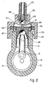
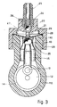
- the present applicants have embodied the small engine shown in the figures with components made of moulded plastics with the exceptions of a shaft 11, spring 24 and spherical ball 22, which in this case consist of a metal, and of a membrane 28, which consists of a soft rubber, in this case silicone rubber, rubber latex, india rubber or another material possessing great resilience.
- a piston 20 of the small engine can have a bore ranging from 4 up to 12-20 mm; this is to show the dimensions involved and the resulting constructional and operating problems.
- a base 10 supports a shaft 11 and contains a flywheel 12 in a crank case 14, the flywheel being integral with the shaft and having the function of a crank.
- the flywheel 12 comprises a pin 13, to which a connecting rod 15 is keyed so as to be able to rotate.
- crank case 14 is closed by a cover 16 which may comprise an outlet hole 17.
- the piston 20 slides in a cylinder 18, which includes outlets or exhaust ports 19 discharging to the outside atmosphere near the bottom dead centre position of the piston.
- the exhaust ports 19 are connected to the crank case 14 and outlet hole 17, and their inclusion makes it possible to obviate the easy entry of dirt into the cylinder 18.
- a cylinder head 26 cooperates with the base 10.
- the connection of the head to the base can be obtained in any known manner.
- a ring 30 is comprised in cooperation with the cylinder head 26 and upper part of the cylinder 18 and provides discharge passages 31 which lead to the exterior 131 in the cylinder head 26.
- the membrane 28, which here comprises a hole 29 at its centre, is fixed between the ring 30 and cylinder head 26 and will advantageously be slightly downwardly cambered at its centre towards the piston 20.
- the membrane 28 is made of a resilient material such as, for instance, a soft rubber, which may be silicone rubber, rubber latex, india rubber or another material possessing a great capacity of expansion in a substantially or completely resilient field.
- a soft rubber such as silicone rubber, rubber latex, india rubber or another material possessing a great capacity of expansion in a substantially or completely resilient field.
- a storage chamber 27 is positioned above the membrane 28.
- the cylinder head 26 comprises an inlet valve 38, which in this example is operated in the neighbourhood of the upper dead centre position of the piston 20 by a projecting rod 21 fixed to the top of the piston, but the valve may be lodged elsewhere and be operated in a different manner.
- valve 38 is opened by the projecting rod 21 when the latter has overcome the thrust of the spring 24 and has displaced the spherical ball 22 from a seating 23.
- the piston descends yet further until it coincides with the exhaust ports 19.
- the gas pours out through the ports 19, the pressure in the expansion chamber falls substantially to zero and the membrane 28 returns fully to its inactive position, thus freeing the discharge passages 31, so that the upward travel of the piston 20 is facilitated since the expansion chamber is now at the ambient pressure.
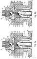
- an automatic valve 41 to discharge the expanded fluid is fitted to the crown of the piston 20 and opens when the pressure within the expansion chamber falls with the opening of the exhaust ports 19 or 40 at the end of the down stroke of the piston.
- This automatic valve 41 consists of a plate 42 equipped with a hollow rod 121, which is thrust upwards by a spring 43 and retained by a head 44 of a pin 45.
- the seating of the valve 41 is machined on the crown of the piston 20, and the body of the piston includes some slots 47 which enable the expanded fluid to be discharged into crank case 14.
- Closure of the valve takes place in the neighbourhood of the top dead position of the piston when the hollow rod 121 meets the spherical ball 22 thrust by the spring 24 and by the pressure of the fluid being fed. Such closure is maintained until the thrust of the fluid in the expansion chamber is overcome by the force of the thrust spring 43.
- Figs. 4a and 4b arranges for the membrane 28 to accompany the stroke of the piston 20 along only a short tract of the same during maximum pressure, thus ensuring a complete seal.
- the resilient edge 48 of the piston 20 is obtained with a radial notch 49 in the plastic material forming the piston 20, so that a wall is produced which becomes progressively thinner until it reaches very small values; the diameter of the resulting upper lip of the wall of the piston is little greater than the inner diameter of the cylinder 18.
- An intermediate valve 39 (Figs. 5 and 6) may be included in an evolutive variant of the invention. This intermediate valve serves to retain the fluid under pressure in the storage chamber 27 for enough time for the piston 20 to leave its upper dead centre position and for the expansion of the fluid to take place only during the descent phase of the piston and therefore during the phase of productive work of the latter.
- This intermediate valve 39 may be positioned in various ways.
- Fig. 5 provides a support disk 35 with a sealing ring 33.
- the support disk 35 comprises at its centre in cooperation with the projecting rod 21 a hollow cone 34, which shuts off or reduces substantially the passage of fluid about the projecting rod 21 so long as the rod 21 is cooperating with the top of the hollow cone 34.
- the support disk 35 comprises a ring 36 consisting of a soft resilient material
- the projecting rod 21 includes a tapered closure portion 32. So long as the tapered portion 32 acts on the central hole of the ring 36, a fluid-tight seal is obtained.
- the small-sized engine of the invention in contrast to the known art of small engines, has its discharge valve open during the whole phase of re-ascent of the piston 20 and therefore its efficiency is better than that of types of engines known in the art owing to its elimination of compression during the re-ascent phase of the piston.
Landscapes
- Engineering & Computer Science (AREA)
- Mechanical Engineering (AREA)
- General Engineering & Computer Science (AREA)
- Chemical & Material Sciences (AREA)
- Combustion & Propulsion (AREA)
- Pistons, Piston Rings, And Cylinders (AREA)
- Fluid-Pressure Circuits (AREA)
- Structures Of Non-Positive Displacement Pumps (AREA)
- Compressor (AREA)
- Actuator (AREA)
Claims (9)
Priority Applications (1)
| Application Number | Priority Date | Filing Date | Title |
|---|---|---|---|
| AT86202346T ATE51936T1 (de) | 1986-03-28 | 1986-12-20 | Kleinmaschine mit fluidantrieb. |
Applications Claiming Priority (2)
| Application Number | Priority Date | Filing Date | Title |
|---|---|---|---|
| IT8333886 | 1986-03-28 | ||
| IT83338/86A IT1191540B (it) | 1986-03-28 | 1986-03-28 | Micromotore a fluido |
Publications (2)
| Publication Number | Publication Date |
|---|---|
| EP0239684A1 EP0239684A1 (de) | 1987-10-07 |
| EP0239684B1 true EP0239684B1 (de) | 1990-04-11 |
Family
ID=11320360
Family Applications (1)
| Application Number | Title | Priority Date | Filing Date |
|---|---|---|---|
| EP86202346A Expired - Lifetime EP0239684B1 (de) | 1986-03-28 | 1986-12-20 | Kleinmaschine mit Fluidantrieb |
Country Status (6)
| Country | Link |
|---|---|
| US (1) | US4766802A (de) |
| EP (1) | EP0239684B1 (de) |
| AT (1) | ATE51936T1 (de) |
| DE (1) | DE3670340D1 (de) |
| ES (1) | ES2011233A4 (de) |
| IT (1) | IT1191540B (de) |
Families Citing this family (5)
| Publication number | Priority date | Publication date | Assignee | Title |
|---|---|---|---|---|
| IT1214182B (it) * | 1987-05-07 | 1990-01-10 | Caenazzo Alessandro Pasqualott | Micromotore a fluido. |
| NZ337744A (en) | 1998-10-26 | 2001-04-27 | Charles D | Piston-to-cylinder seal for a pneumatic engine with pressure dependent, variable sealing diameter |
| US6626079B1 (en) | 2002-03-28 | 2003-09-30 | Rehco, Llc | Pneumatic motor |
| WO2016146159A1 (en) * | 2015-03-16 | 2016-09-22 | Aross 3D Gmbh | Steam engine |
| FR3115313B1 (fr) * | 2020-10-15 | 2023-11-03 | Reyal Jean Pierre | Système d'injection d'air comprimé dans un moteur à air comprimé. |
Family Cites Families (12)
| Publication number | Priority date | Publication date | Assignee | Title |
|---|---|---|---|---|
| BE355350A (de) * | ||||
| US1266252A (en) * | 1917-05-09 | 1918-05-14 | Louis Hadford | Pump. |
| US2588478A (en) * | 1946-11-27 | 1952-03-11 | William L Brown | Engine |
| JPS4929542B1 (de) * | 1966-09-24 | 1974-08-05 | ||
| DE2024427A1 (de) * | 1970-05-20 | 1971-12-02 | Neuhaus G | Selbstsperrendes Ventil |
| US3703848A (en) * | 1970-09-14 | 1972-11-28 | William L Brown | Fluid pressure engine |
| US3910160A (en) * | 1974-11-01 | 1975-10-07 | William J Divine | Uniflow steam engine |
| US3995535A (en) * | 1975-05-23 | 1976-12-07 | Russell Ozechowski | Expansible chamber device |
| US4190024A (en) * | 1977-07-21 | 1980-02-26 | Robert Davis | Variable chamber diesel engine |
| GB2018366A (en) * | 1978-03-31 | 1979-10-17 | Boc Ltd | Gas-operated motors |
| DE2912556A1 (de) * | 1978-03-31 | 1980-02-14 | Boc Ltd | Gasmotor |
| GB2029908A (en) * | 1978-09-05 | 1980-03-26 | Rilett J W | Motors and gas supply apparatus therefor |
-
1986
- 1986-03-28 IT IT83338/86A patent/IT1191540B/it active
- 1986-12-20 EP EP86202346A patent/EP0239684B1/de not_active Expired - Lifetime
- 1986-12-20 AT AT86202346T patent/ATE51936T1/de not_active IP Right Cessation
- 1986-12-20 DE DE8686202346T patent/DE3670340D1/de not_active Expired - Lifetime
- 1986-12-20 ES ES86202346T patent/ES2011233A4/es active Pending
-
1987
- 1987-03-27 US US07/030,622 patent/US4766802A/en not_active Expired - Fee Related
Also Published As
| Publication number | Publication date |
|---|---|
| US4766802A (en) | 1988-08-30 |
| IT1191540B (it) | 1988-03-23 |
| DE3670340D1 (de) | 1990-05-17 |
| IT8683338A0 (it) | 1986-03-28 |
| ATE51936T1 (de) | 1990-04-15 |
| EP0239684A1 (de) | 1987-10-07 |
| ES2011233A4 (es) | 1990-01-01 |
Similar Documents
| Publication | Publication Date | Title |
|---|---|---|
| US5927584A (en) | Pneumatic fastener driving tool having air exhaust arrangement | |
| US4773305A (en) | Piston pump with rolling membrane | |
| US6193482B1 (en) | Structure of a piston of an air-filing device | |
| US4030655A (en) | Improved fastener applying device | |
| US4766802A (en) | Small-sized engine operated by fluid | |
| US4885978A (en) | Fluid-operated miniature engine | |
| US3910160A (en) | Uniflow steam engine | |
| US5395216A (en) | Portable car-used oil extracting and tire inflation apparatus with separately disposed oil and air pumps | |
| US2556680A (en) | Valve mechanism for reciprocatory fluid pressure operated motors | |
| CN2542892Y (zh) | 内平衡式气动截止阀 | |
| US2914047A (en) | Automatic booster piston for internal combustion engines | |
| US20030209013A1 (en) | Piston air engine | |
| US3181566A (en) | Control valve for pneumatic equipment | |
| US4879943A (en) | Expansible chamber motor with snap-acting valve | |
| US5676380A (en) | Venting piston ring | |
| US5809947A (en) | Piston valve | |
| CN209228562U (zh) | 一种气动高压注油器的空气泵 | |
| JPH0658046B2 (ja) | 往復ピストン機関のスリーブ端バルブ | |
| JP2531502Y2 (ja) | シリンダライナ | |
| CN106939808A (zh) | 一种应用于低速柴油机的带液压旋阀器的排气阀装置 | |
| CN207485639U (zh) | 无油空压机气阀结构 | |
| US671044A (en) | Air-compressor. | |
| US6230605B1 (en) | Piston-to-cylinder seal for a pneumatic engine | |
| FR2358565A1 (fr) | Moteur actionne par un fluide sous pression | |
| US760843A (en) | Elastic-fluid compressor. |
Legal Events
| Date | Code | Title | Description |
|---|---|---|---|
| PUAI | Public reference made under article 153(3) epc to a published international application that has entered the european phase |
Free format text: ORIGINAL CODE: 0009012 |
|
| AK | Designated contracting states |
Kind code of ref document: A1 Designated state(s): AT BE CH DE ES FR GB GR IT LI NL SE |
|
| 17P | Request for examination filed |
Effective date: 19880218 |
|
| 17Q | First examination report despatched |
Effective date: 19880616 |
|
| GRAA | (expected) grant |
Free format text: ORIGINAL CODE: 0009210 |
|
| AK | Designated contracting states |
Kind code of ref document: B1 Designated state(s): AT BE CH DE ES FR GB GR IT LI NL SE |
|
| PG25 | Lapsed in a contracting state [announced via postgrant information from national office to epo] |
Ref country code: IT Free format text: LAPSE BECAUSE OF FAILURE TO SUBMIT A TRANSLATION OF THE DESCRIPTION OR TO PAY THE FEE WITHIN THE PRE;WARNING: LAPSES OF ITALIAN PATENTS WITH EFFECTIVE DATE BEFORE 2007 MAY HAVE OCCURRED AT ANY TIME BEFORE 2007. THE CORRECT EFFECTIVE DATE MAY BE DIFFERENT FROM THE ONE RECORDED.SCRIBED TIME-LIMIT Effective date: 19900411 Ref country code: SE Effective date: 19900411 Ref country code: GR Free format text: LAPSE BECAUSE OF FAILURE TO SUBMIT A TRANSLATION OF THE DESCRIPTION OR TO PAY THE FEE WITHIN THE PRESCRIBED TIME-LIMIT Effective date: 19900411 Ref country code: AT Effective date: 19900411 Ref country code: BE Effective date: 19900411 Ref country code: NL Effective date: 19900411 |
|
| REF | Corresponds to: |
Ref document number: 51936 Country of ref document: AT Date of ref document: 19900415 Kind code of ref document: T |
|
| REF | Corresponds to: |
Ref document number: 3670340 Country of ref document: DE Date of ref document: 19900517 |
|
| ET | Fr: translation filed | ||
| PG25 | Lapsed in a contracting state [announced via postgrant information from national office to epo] |
Ref country code: ES Free format text: LAPSE BECAUSE OF FAILURE TO SUBMIT A TRANSLATION OF THE DESCRIPTION OR TO PAY THE FEE WITHIN THE PRESCRIBED TIME-LIMIT Effective date: 19900722 |
|
| NLV1 | Nl: lapsed or annulled due to failure to fulfill the requirements of art. 29p and 29m of the patents act | ||
| PG25 | Lapsed in a contracting state [announced via postgrant information from national office to epo] |
Ref country code: CH Effective date: 19901231 Ref country code: LI Effective date: 19901231 |
|
| PLBE | No opposition filed within time limit |
Free format text: ORIGINAL CODE: 0009261 |
|
| STAA | Information on the status of an ep patent application or granted ep patent |
Free format text: STATUS: NO OPPOSITION FILED WITHIN TIME LIMIT |
|
| 26N | No opposition filed | ||
| REG | Reference to a national code |
Ref country code: CH Ref legal event code: PL |
|
| PGFP | Annual fee paid to national office [announced via postgrant information from national office to epo] |
Ref country code: FR Payment date: 19911129 Year of fee payment: 6 |
|
| PGFP | Annual fee paid to national office [announced via postgrant information from national office to epo] |
Ref country code: DE Payment date: 19911217 Year of fee payment: 6 |
|
| PGFP | Annual fee paid to national office [announced via postgrant information from national office to epo] |
Ref country code: GB Payment date: 19911218 Year of fee payment: 6 |
|
| PG25 | Lapsed in a contracting state [announced via postgrant information from national office to epo] |
Ref country code: GB Effective date: 19921220 |
|
| GBPC | Gb: european patent ceased through non-payment of renewal fee |
Effective date: 19921220 |
|
| PG25 | Lapsed in a contracting state [announced via postgrant information from national office to epo] |
Ref country code: FR Effective date: 19930831 |
|
| PG25 | Lapsed in a contracting state [announced via postgrant information from national office to epo] |
Ref country code: DE Effective date: 19930901 |
|
| REG | Reference to a national code |
Ref country code: FR Ref legal event code: ST |