EP0238175A2 - Präsentierständer - Google Patents
Präsentierständer Download PDFInfo
- Publication number
- EP0238175A2 EP0238175A2 EP87300664A EP87300664A EP0238175A2 EP 0238175 A2 EP0238175 A2 EP 0238175A2 EP 87300664 A EP87300664 A EP 87300664A EP 87300664 A EP87300664 A EP 87300664A EP 0238175 A2 EP0238175 A2 EP 0238175A2
- Authority
- EP
- European Patent Office
- Prior art keywords
- bar
- article
- support means
- display stand
- stand according
- Prior art date
- Legal status (The legal status is an assumption and is not a legal conclusion. Google has not performed a legal analysis and makes no representation as to the accuracy of the status listed.)
- Withdrawn
Links
Images


Classifications
-
- A—HUMAN NECESSITIES
- A47—FURNITURE; DOMESTIC ARTICLES OR APPLIANCES; COFFEE MILLS; SPICE MILLS; SUCTION CLEANERS IN GENERAL
- A47F—SPECIAL FURNITURE, FITTINGS, OR ACCESSORIES FOR SHOPS, STOREHOUSES, BARS, RESTAURANTS OR THE LIKE; PAYING COUNTERS
- A47F7/00—Show stands, hangers, or shelves, adapted for particular articles or materials
- A47F7/02—Show stands, hangers, or shelves, adapted for particular articles or materials for jewellery, dentures, watches, eye-glasses, lenses, or the like
- A47F7/024—Show stands, hangers, or shelves, adapted for particular articles or materials for jewellery, dentures, watches, eye-glasses, lenses, or the like with provisions for preventing unauthorised removal
Definitions
- the invention relates to display stands suitable for personal adornments, chains, bangles and watches at point of sale.
- the invention provides a display stand which comprises an upright member, a number of fixed arms projecting forward from the upright member and provided with article support means, a bar movable in relation to each arm from a first position in which the bar renders it impossible to remove an article from the support means to a second position in which an article can be removed, and means for locking the bar in the first position.
- Each arm is preferably provided with a fixed cross member having article support means, and the bar with a corresponding cross member.
- the article support means should be provided with a projection or projections to prevent an article being slid off the end.
- the bar cross member is preferably provided with flanges movable adjacent the ends of the article support means to help prevent an article being slid off the end.
- the means for locking is preferably on a flange projecting from the bar and engageable with the upright member.
- the article support means preferably comprises a curved surface suitable for receiving a bangle, and/or may be provided with a number of upright pins approaching close to the bar for passing through a link in a chain, or a buckle or ring so as to help in preventing removal of the article.
- An article can be removed for sale by a shop assistant unlocking the bar, and moving it to its second position.
- the article support means may be loaded with articles when the bar is in its second position, and the articles secured by moving the bar to its first position and locking.
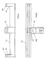
- the display stand comprises an upright member 10, three fixed arms 12 projecting forward from the upright 10 and provided with article support means 14, a bar 16 movable in relation to each arm 12, and means 18 for locking each bar 12 in relation to the upright 10.
- the upright 10 comprises two posts 20 secured to a base 21 and bearing fabric-covered panels 22 (Figure 3) front and back.
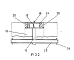
- Three cross pieces 24 ( Figure 2) are screwed at one end to each of the posts 20, and having one of the arms 12 welded thereto and projecting forward therefrom.
- the arms 12 each have a cross member fixed at the outer end bearing curved article support means 14 consisting of a plastics injection moulding.
- the arms 12 themselves are similarly covered, having a plastics injection moulding secured thereto by a bolt 26 ( Figure 3).
- the details of the bars 16 are best seen in Figure 3 where they have been indicated only adjacent the uppermost arm 12.
- the bar 16 has a fixed cross member 28 with flanges 30 projecting downward adjacent the ends of the article support means 14 to help prevent an article being slid off the end.
- the bar 16 is provided with an upward-projecting flange 32 to the rear of the upright 10.
- the flange 32 is provided with a hole through which the locking means 18 or catch projects into the back of the upright 10, and can be used to secure the bar 16 in its first or locked position so as to engage with the upright 10.
- the article support means 14 are each provided with a projection 34 at each end to prevent an article being slid off and removed.
- the uppermost article support means 14 is provided with a number of upright pins 38 approaching close to the cross member 28 of the bar 16 for passing through a link in a chain, for example, so as to help in preventing its removal.
- the lower two article support means 14 have no pins 38, but are suitable for displaying a bangle, for example.
- All the bars 16 in the drawings are shown in their first position in which they render it impossible to remove an article from the support means 14. It can readily be seen that an annular article passing between the support means 14 and the bar 16 can only be removed by breaking the article. By unlocking the catch 18 from the upright 10, the bar 16 can be slid to the left ( Figure 3), and thus separated by a short distance from the article support means 14. In this second position of the bar 16, an annular article can be loaded onto the article support means 14 or removed therefrom by lifting over either of the ends of the support means 14. The bar 16 can then be slid back rightward to the first or locking position shown in the drawings.
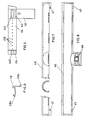
- a modified arm 112 of Figures 4 to 6 consists of plastics injection mouldings adhering together to form a unit having a cross member with a curved article support means 114.
- the means 114 are provided with a projection 134 at each end to prevent an article being slid off.
- the side shown in Figure 6 is provided with optional pins 128 to separate articles and help in preventing removal.
- the projections 134 and the arm 112 have at the top a flange 140 with lateral projections along which a bar 116 ( Figures 7 and 8) can be slid to left or right.
- Locking means 118 secures the arm 116 in a (first) position directly of the article support means 114 so that an article cannot be removed.
- the locking mean 118 comprises a catch receivable in a recess 119 in the lower side of the bar 116 for locking the bar 116 in the first position.
- the locking means 118 consists of an L-shaped piece of plastics material (see Figure 9) with the catch at the central or angled portion, secured at one end 118a to the inside of the bar 112, and having at the other end 118b a release member visible in Figure 5. Finger pressure on the release member flexes the locking means 118, withdraws the catch, and releases the bar 116 for sliding movement to left or right.
Landscapes
- Display Racks (AREA)
Applications Claiming Priority (2)
| Application Number | Priority Date | Filing Date | Title |
|---|---|---|---|
| GB868607115A GB8607115D0 (en) | 1986-03-21 | 1986-03-21 | Display apparatus |
| GB8607115 | 1986-03-21 |
Publications (2)
| Publication Number | Publication Date |
|---|---|
| EP0238175A2 true EP0238175A2 (de) | 1987-09-23 |
| EP0238175A3 EP0238175A3 (de) | 1989-05-03 |
Family
ID=10595050
Family Applications (1)
| Application Number | Title | Priority Date | Filing Date |
|---|---|---|---|
| EP87300664A Withdrawn EP0238175A3 (de) | 1986-03-21 | 1987-01-27 | Präsentierständer |
Country Status (3)
| Country | Link |
|---|---|
| US (1) | US4727992A (de) |
| EP (1) | EP0238175A3 (de) |
| GB (1) | GB8607115D0 (de) |
Cited By (2)
| Publication number | Priority date | Publication date | Assignee | Title |
|---|---|---|---|---|
| GB2239343A (en) * | 1989-12-21 | 1991-06-26 | Ver Kettenfabriken Gmbh | Display and sales stand for chains, hoses and similar materials |
| DE10358950A1 (de) * | 2003-12-15 | 2005-07-07 | Ewald Haas | Diebstahlgesichertes Display |
Families Citing this family (4)
| Publication number | Priority date | Publication date | Assignee | Title |
|---|---|---|---|---|
| US5039044A (en) * | 1988-10-20 | 1991-08-13 | Sher Joseph M | Vertically adjustable holder |
| US8167253B2 (en) * | 2008-06-02 | 2012-05-01 | Sony Corporation | Flat panel TV stand providing floating appearance |
| US20140203156A1 (en) * | 2013-01-22 | 2014-07-24 | Wild West Investments, LLC | Apparatus and method of manufacture of stand for supporting an electronic device |
| US11071397B1 (en) * | 2013-06-10 | 2021-07-27 | Gregory Allen Sprunk | Stand for holding smart watch bands |
Citations (4)
| Publication number | Priority date | Publication date | Assignee | Title |
|---|---|---|---|---|
| FR2031880A5 (de) * | 1969-02-11 | 1970-11-20 | See Jacques | |
| US3768662A (en) * | 1971-10-27 | 1973-10-30 | Telesco Brophey Ltd | Anti-pilferage umbrella stand |
| FR2427076A1 (fr) * | 1978-06-02 | 1979-12-28 | Villain Andre | Presentoir |
| FR2545343A1 (fr) * | 1983-05-05 | 1984-11-09 | Albouze Maurice | Presentoir rayonnant a securite |
Family Cites Families (6)
| Publication number | Priority date | Publication date | Assignee | Title |
|---|---|---|---|---|
| US3570676A (en) * | 1969-06-02 | 1971-03-16 | Mayer & Assoc Frank | Theftproof merchandise display |
| US3674156A (en) * | 1970-08-14 | 1972-07-04 | Chicago Show Printing Co | Display assembly and element therefor |
| US3805962A (en) * | 1972-06-19 | 1974-04-23 | A Bendiksen | Arrangement in combined display and sales racks |
| US4300690A (en) * | 1978-05-19 | 1981-11-17 | Securax, Inc. | Security display rack |
| US4420084A (en) * | 1982-05-17 | 1983-12-13 | Whelan Elizabeth M | Jewelry holding device |
| US4629263A (en) * | 1984-10-04 | 1986-12-16 | Hendriks John G | Cabinet drawer bar retaining mechanism |
-
1986
- 1986-03-21 GB GB868607115A patent/GB8607115D0/en active Pending
-
1987
- 1987-01-27 EP EP87300664A patent/EP0238175A3/de not_active Withdrawn
- 1987-02-12 US US07/013,945 patent/US4727992A/en not_active Expired - Fee Related
Patent Citations (4)
| Publication number | Priority date | Publication date | Assignee | Title |
|---|---|---|---|---|
| FR2031880A5 (de) * | 1969-02-11 | 1970-11-20 | See Jacques | |
| US3768662A (en) * | 1971-10-27 | 1973-10-30 | Telesco Brophey Ltd | Anti-pilferage umbrella stand |
| FR2427076A1 (fr) * | 1978-06-02 | 1979-12-28 | Villain Andre | Presentoir |
| FR2545343A1 (fr) * | 1983-05-05 | 1984-11-09 | Albouze Maurice | Presentoir rayonnant a securite |
Cited By (3)
| Publication number | Priority date | Publication date | Assignee | Title |
|---|---|---|---|---|
| GB2239343A (en) * | 1989-12-21 | 1991-06-26 | Ver Kettenfabriken Gmbh | Display and sales stand for chains, hoses and similar materials |
| GB2239343B (en) * | 1989-12-21 | 1994-04-27 | Ver Kettenfabriken Gmbh | Display stand for chains, hoses cables and the like |
| DE10358950A1 (de) * | 2003-12-15 | 2005-07-07 | Ewald Haas | Diebstahlgesichertes Display |
Also Published As
| Publication number | Publication date |
|---|---|
| US4727992A (en) | 1988-03-01 |
| EP0238175A3 (de) | 1989-05-03 |
| GB8607115D0 (en) | 1986-04-30 |
Similar Documents
| Publication | Publication Date | Title |
|---|---|---|
| CN101578422B (zh) | 具有固定自由端的展示钩组件 | |
| CA2508188C (en) | Locking attachment for product display hooks | |
| US4466540A (en) | Merchandizing package | |
| US20050073413A1 (en) | Alarming merchandise display system | |
| US9240090B2 (en) | Security shelving apparatus and method for securely storing and/or dispensing retail articles | |
| EP1227744B1 (de) | Sicherheitseinrichtung zur verhinderung von schneller abfuhr von waren | |
| CN101426408A (zh) | 展示杆的锁定机构 | |
| KR100654247B1 (ko) | 진열대 | |
| ATE158053T1 (de) | Diebstahlsicherer schaukasten | |
| US4727992A (en) | Display stands | |
| US20070224879A1 (en) | Adapter For Attaching An Electronic Shelf Labet To A Blister Hook | |
| SE9103326A (de) | ||
| US4011942A (en) | Wristwatch display case having detachable flexible watch-supporting cuff | |
| WO2001029354A1 (en) | Tack assembly for electronic article surveillance tags | |
| US7780000B2 (en) | Anti-theft display container | |
| US20040000558A1 (en) | Blister hook display | |
| US3570676A (en) | Theftproof merchandise display | |
| US20130181583A1 (en) | Mounted display case | |
| US5363575A (en) | Display card holder | |
| US20230255366A1 (en) | System for presentation of self-service items | |
| FR2436276A1 (fr) | Dispositif pour l'accrochage de petits articles de maroquinerie ou autres, sur un presentoir ou similaire | |
| JPH0975185A (ja) | 商品の陳列台 | |
| CA2459228C (en) | Rail for checkout dividers | |
| SE523369C2 (sv) | Låsbart upphängningssystem för varuexponering | |
| IT202100025916A1 (it) | Borchia per articolo di gioielleria con inserto intercambiabile. |
Legal Events
| Date | Code | Title | Description |
|---|---|---|---|
| PUAI | Public reference made under article 153(3) epc to a published international application that has entered the european phase |
Free format text: ORIGINAL CODE: 0009012 |
|
| AK | Designated contracting states |
Kind code of ref document: A2 Designated state(s): DE FR GB IT NL |
|
| PUAL | Search report despatched |
Free format text: ORIGINAL CODE: 0009013 |
|
| AK | Designated contracting states |
Kind code of ref document: A3 Designated state(s): DE FR GB IT NL |
|
| 17P | Request for examination filed |
Effective date: 19890919 |
|
| 17Q | First examination report despatched |
Effective date: 19900222 |
|
| STAA | Information on the status of an ep patent application or granted ep patent |
Free format text: STATUS: THE APPLICATION HAS BEEN WITHDRAWN |
|
| 18W | Application withdrawn |
Withdrawal date: 19900612 |
|
| R18W | Application withdrawn (corrected) |
Effective date: 19900612 |
|
| RIN1 | Information on inventor provided before grant (corrected) |
Inventor name: SHARP, JOHN MICHAEL |