EP0237759A2 - Vehicle roof - Google Patents
Vehicle roof Download PDFInfo
- Publication number
- EP0237759A2 EP0237759A2 EP87101704A EP87101704A EP0237759A2 EP 0237759 A2 EP0237759 A2 EP 0237759A2 EP 87101704 A EP87101704 A EP 87101704A EP 87101704 A EP87101704 A EP 87101704A EP 0237759 A2 EP0237759 A2 EP 0237759A2
- Authority
- EP
- European Patent Office
- Prior art keywords
- frame
- lid
- extended
- vehicle
- sun
- Prior art date
- Legal status (The legal status is an assumption and is not a legal conclusion. Google has not performed a legal analysis and makes no representation as to the accuracy of the status listed.)
- Granted
Links
Images

Classifications
-
- B—PERFORMING OPERATIONS; TRANSPORTING
- B60—VEHICLES IN GENERAL
- B60J—WINDOWS, WINDSCREENS, NON-FIXED ROOFS, DOORS, OR SIMILAR DEVICES FOR VEHICLES; REMOVABLE EXTERNAL PROTECTIVE COVERINGS SPECIALLY ADAPTED FOR VEHICLES
- B60J7/00—Non-fixed roofs; Roofs with movable panels, e.g. rotary sunroofs
- B60J7/0007—Non-fixed roofs; Roofs with movable panels, e.g. rotary sunroofs moveable head-liners, screens, curtains or blinds for ceilings
- B60J7/0015—Non-fixed roofs; Roofs with movable panels, e.g. rotary sunroofs moveable head-liners, screens, curtains or blinds for ceilings roller blind
-
- B—PERFORMING OPERATIONS; TRANSPORTING
- B60—VEHICLES IN GENERAL
- B60J—WINDOWS, WINDSCREENS, NON-FIXED ROOFS, DOORS, OR SIMILAR DEVICES FOR VEHICLES; REMOVABLE EXTERNAL PROTECTIVE COVERINGS SPECIALLY ADAPTED FOR VEHICLES
- B60J7/00—Non-fixed roofs; Roofs with movable panels, e.g. rotary sunroofs
- B60J7/08—Non-fixed roofs; Roofs with movable panels, e.g. rotary sunroofs of non-sliding type, i.e. movable or removable roofs or panels, e.g. let-down tops or roofs capable of being easily detached or of assuming a collapsed or inoperative position
- B60J7/16—Non-fixed roofs; Roofs with movable panels, e.g. rotary sunroofs of non-sliding type, i.e. movable or removable roofs or panels, e.g. let-down tops or roofs capable of being easily detached or of assuming a collapsed or inoperative position non-foldable and rigid, e.g. a one-piece hard-top or a single rigid roof panel
- B60J7/1628—Non-fixed roofs; Roofs with movable panels, e.g. rotary sunroofs of non-sliding type, i.e. movable or removable roofs or panels, e.g. let-down tops or roofs capable of being easily detached or of assuming a collapsed or inoperative position non-foldable and rigid, e.g. a one-piece hard-top or a single rigid roof panel for covering the passenger compartment
- B60J7/1635—Non-fixed roofs; Roofs with movable panels, e.g. rotary sunroofs of non-sliding type, i.e. movable or removable roofs or panels, e.g. let-down tops or roofs capable of being easily detached or of assuming a collapsed or inoperative position non-foldable and rigid, e.g. a one-piece hard-top or a single rigid roof panel for covering the passenger compartment of non-convertible vehicles
- B60J7/1642—Roof panels, e.g. sunroofs or hatches, movable relative to the main roof structure, e.g. by lifting or pivoting
Abstract
Description
Die Erfindung bezieht sich auf ein Fahrzeugdach mit einem eine Dachöffnung mindestens teilweise umgebenden Rahmen, einem Dekkel, der in einer Schließstellung die Dachöffnung verschließt und der durch Schwenken gegenüber dem Rahmen um eine nahe seiner Vorderkante liegende Schwenkachse mit seiner Hinterkante über die feste Dachfläche ausstellbar ist, sowie zwei unterhalb des Deckels zu beiden Seiten der Fahrzeuglängsmittelachse am Rahmen angebrachten Rollovorrichtungen mit jeweils einer quer zur Fahrzeuglängsmittelachse verstellbaren Sonnenschutzblende.The invention relates to a vehicle roof with a frame which at least partially surrounds a roof opening, a cover which closes the roof opening in a closed position and which can be pivoted with respect to the frame about a pivot axis lying near its front edge with its rear edge over the fixed roof surface, as well as two roller blind devices attached to the frame below the cover on both sides of the vehicle's longitudinal center axis, each with a sun visor adjustable transversely to the vehicle's longitudinal center axis.
Bei einem bekannten Fahrzeugdach dieser Art (DE-OS 24 17 983) liegen die Befestigungspunkte für die Rollovorrichtungen und die dazu parallelen Längskanten der freien Enden der Sonnenschutzblenden an gegenüberliegenden Streben des Rahmens. Wenn bei dem bekannten Fahrzeugdach der Deckel ausgestellt und die Sonnenschutzblenden beide ausgefahren werden, ist die durch das Ausstellen des Deckels angestrebte Belüftung des Fahrzeuginnenraumes praktisch vereitelt oder mindestens stark beeinträchtigt, weil die ausgefahrenen Sonnenschutzblenden die Dachöffnung im wesentlichen verschließen.In a known vehicle roof of this type (DE-OS 24 17 983), the fastening points for the roller blind devices and the parallel longitudinal edges of the free ends of the sun visors are located on opposite struts of the frame. If in the known vehicle roof the cover is opened and the sun visors are both extended, the ventilation of the vehicle interior aimed at by the opening of the cover is practically prevented or at least severely impaired because the extended sun visors essentially close the roof opening.
Der im Anspruch 1 angegebenen Erfindung liegt die Aufgabe zugrunde, ein Fahrzeugdach der eingangs genannten Art zu schaffen, das eine wirkungsvolle Belüftung des Fahrzeuginnenraums auch dann gewährleistet, wenn bei ausgestelltem Deckel die Sonnenschutzblenden ausgefahren werden, und bei dem gleichwohl die Befestigung und Führung der Rollovorrichtungen und deren Sonnenschutzblenden einfach und sicher aufgebaut werden können.The invention specified in claim 1 has for its object to provide a vehicle roof of the type mentioned, which ensures effective ventilation of the vehicle interior even when the sun visors are extended with the cover open, and in which the fastening and guiding of the roller blinds and whose sun visors can be installed easily and safely.
Diese Aufgabe wird erfindungsgemäß dadurch gelöst, daß die Sonnenschutzblenden im ausgefahrenen Zustand im Bereich ihres freien Endes vorne an dem Rahmen und hinten an dem Deckel gehalten sind.This object is achieved in that the sun visors are held in the extended state in the region of their free end on the front of the frame and on the back of the cover.
Bei dem erfindungsgemäßen Fahrzeugdach macht die ausgefahrene Sonnenschutzblende die Ausstellbewegung des Deckels mindestens teilweise mit. Wird der Deckel ausgestellt, wird die ausgefahrene Sonnenschutzblende an ihrem freien Ende hinten mitangehoben. Dadurch wird eine einwandfreie Fahrzeugbelüftung in Kombination mit einem wirkungsvollen Sonnenschutz sichergestellt, unabhängig davon, wie weit der Deckel jeweils ausgestellt wird. Durch die Mitnahme der ausgefahrenen Sonnenschutzblende beim Ausstellen des Deckels wird zugleich einem Flattern der Sonnenschutzblende entgegengewirkt.In the vehicle roof according to the invention, the extended sun visor at least partially participates in the opening movement of the cover. If the cover is opened, the extended sunshield is lifted at the free end at the back. This ensures proper ventilation in combination with effective sun protection, regardless of how far the cover is opened. Carrying the extended sun visor when the cover is opened also counteracts a fluttering of the sun visor.
Grundsätzlich ist es zwar möglich, die beiden Rollovorrichtungen im mittleren Bereich des Rahmens anzuordnen und dementsprechend die Sonnenschutzblenden seitlich nach außen auszufahren. Vorzugsweise sind jedoch die Rollovorrichtungen zu beiden Seiten des Rahmens angeordnet, und im Bereich der Fahrzeuglängsmittelachse sind Widerlager für die ausgefahrenen Sonnenschutzblenden vorne am Rahmen und hinten an der Deckelunterseite angebracht. Die seitliche Anordnung der Rollovorrichtungen erlaubt bei eingefahrenen Sonnenschutzblenden eine im mittleren Deckelbereich unbehinderte Sicht durch den zweckmäßig aus Glas oder einem anderen durchsichtigen Werkstoff gefertigten Deckel.In principle, it is possible to arrange the two roller blind devices in the central region of the frame and accordingly to extend the sun visors laterally outwards. However, the roller blind devices are preferably arranged on both sides of the frame, and in the region of the vehicle's longitudinal center axis, abutments for the extended sun visors are attached to the front of the frame and to the rear of the underside of the cover. The lateral arrangement of the roller blind devices allows an unobstructed view in the central area of the cover when the sun protection blinds are retracted through the cover, which is expediently made of glass or some other transparent material.
In vorteilhafter weiterer Ausgestaltung der Erfindung sind die Sonnenschutzblenden an ihrem freien Ende mit jeweils einer vorne und hinten über das freie Sonnenschutzblendenende vorragenden Verstärkungsleiste versehen, und bei ausgefahrender Sonnenschutzblende ist die zugehörige Verstärkungsleiste vorne mit einem rahmenfesten Widerlager und hinten mit einem deckelfesten Widerlager in Eingriff bringbar. Dies trägt zu einem einfachen Aufbau und zu einer stabilen Halterung der ausgefahrenen Sonnenschutzblenden bei.In an advantageous further embodiment of the invention, the sunshades are provided at their free ends with a reinforcement strip projecting from the front and rear over the free sunshield end, and when the sunshade is extended, the associated reinforcement strip can be engaged at the front with a frame-fixed abutment and at the rear with a cover-fixed abutment. This contributes to a simple structure and to a stable mounting of the extended sun visors.
Vorzugsweise sind die Widerlager ferner derart ausgebildet und angeordnet, daß die freien Enden der Sonnenschutzblenden spaltfrei oder näherungsweise spaltfrei zusammentreffen, wenn beide Sonnenblenden ausgefahren sind. Die Sonnenblenden geben in einem solchen Fall im eingefahrenen Zustand nahezu die gesamte Dachöffnung frei und decken andererseits im ausgefahrenen Zustand praktisch den gesamten Hebedachbereich gegen Sonneneinstrahlung ab.Preferably, the abutments are further designed and arranged such that the free ends of the sun visors meet without a gap or approximately without a gap, if both Sun visors are extended. In such a case, the sun visors expose almost the entire roof opening when retracted and, on the other hand, cover practically the entire area of the sunroof when extended.
Vorteilhaft liegt sowohl in der Deckelschließstellung als auch bei ausgestelltem Deckel der vordere Rand der ausgefahrenen Sonnenschutzblenden in lotrechter Richtung zwischen dem die Dachöffnung nach vorne begrenzenden Rahmeninnenrand und dem Deckel. Entsprechend liegt vorzugsweise mindestens in der Deckelschließstellung der hintere Rand der ausgefahrenen Sonnenschutzblenden in lotrechter Richtung zwischen dem die Dachöffnung nach hinten begrenzenden Rahmeninnenrand und dem Deckel. Durch ein solches Überstehen der Ränder der ausgefahrenen Sonnenschutzblenden über den vorderen und/oder den hinteren Rahmeninnenrand wird einem Flattern der Sonnenschutzblenden zusätzlch entgegengewirkt. Es wird sowohl von innen als auch von außen ein besonders ansprechendes Aussehen des Fahrzeugdachs auch bei ausgefahrenen Sonnenschutzblenden gewährleistet.Advantageously, both in the lid closed position and when the lid is open, the front edge of the extended sun visors lies in a vertical direction between the inner edge of the frame that limits the roof opening to the front and the lid. Correspondingly, the rear edge of the extended sun protection blinds preferably lies at least in the lid closed position in the vertical direction between the inner frame edge bordering the roof opening to the rear and the lid. By protruding the edges of the extended sun visors over the front and / or the rear frame inner edge, fluttering of the sun visors is additionally counteracted. A particularly attractive appearance of the vehicle roof is guaranteed both from the inside and from the outside, even when the sunshades are extended.
Ein bevorzugtes Ausführungsbeispiel der Erfindung ist im folgenden anhand der Zeichnungen näher erläutert. Es zeigen:
- Fig. 1 eine Draufsicht auf den linken Teil eines erfindungsgemäßen Fahrzeugdachs, teilweise abgebrochen und unter Weglassung des Deckels,
- Fig. 2 einen Schnitt entlang der Linie II-II der Fig. 1,
- Fign. 3 und 4 einen Schnitt entlang der Linie III-III der Fig. 1 in der Deckelschließstellung bzw. bei ausgestelltem Deckel, und
- Fig. 5 einen Schnitt entlang der Linie V-V der Fig. 1.
- 1 is a plan view of the left part of a vehicle roof according to the invention, partially broken off and with the cover omitted,
- 2 shows a section along the line II-II of FIG. 1,
- Fig. 3 and 4 a section along the line III-III of FIG. 1 in the lid closed position or with the lid open, and
- 5 shows a section along the line VV of FIG. 1st
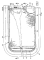
Das veranschaulichte Fahrzeugdach ist als Hebedach mit einem einteiligen Kunststoffrahmen 10 ausgebildet, der in an sich bekannter, nicht näher dargestellter Weise einen vorzugsweise abnehmbaren Deckel 11 aus durchsichtigem oder durchscheinendem Werkstoff trägt. Der Deckel 11 kann mittels einer Ausstellvorrichtung 12 um eine nahe seiner Vorderkante liegende Schwenkachse verschwenkt und dadurch mit seiner Hinterkante 13 über die feste Dachfläche 14 ausgestellt werden. Die Ausstellvorrichtung kann in beliebiger bekannter Weise ausgebildet sein. Beispielsweise kann es sich um einen handbetätigten Drehgriff oder eine motorisch angetriebene Ausstellvorrichtung (DE-PS 25 08 487, DE-PS 27 10 193, DE-PS 31 14 502) handeln. In den Fign. 1, 3 und 4 ist beispielshalber ein handbetätigter Dreh-Klappgriff angedeutet, wie er im einzelnen in der älteren Anmeldung PCT/GB 85/00090 offenbart ist. Die Ausstellvorrichtung 12 ist einerseits im mittleren hinteren Bereich des Rahmens 10 abgestützt und steht andererseits mit dem Deckel 11 nahe dessen Hinterkante 13 in Verbindung.The vehicle roof illustrated is designed as a lifting roof with a one-piece
Der Rahmen 10 sitzt unterhalb der festen Dachfläche 14. Er stützt sich dabei mit Nasen 16, 17 an der Unterseite der Dachfläche 14 ab. Die Nasen 17, 16 begrenzen rillenförmige Aufnahmeräume für eine Dicht- und/oder Klebmasse 18. Ein im Querschnitt im wesentlichen Z-förmiger Trimmring 19 weist einen nach außen abstehenden Flansch 20 auf, der sich im Randbereich einer mittels des Deckels 11 verschließbaren Dachöffnung 21 gegen die Außenseite der festen Dachfläche 14 anlegt. Ein Steg 22 des Trimmrings 19 greift durch die Dachöffnung 21 hindurch und geht unten in einen nach innen abgewinkelten Flansch 23 über. Der Steg 22 und der Flansch 23 greifen in einen umlaufenden Schlitz 24 des Rahmens 10 ein. Der Steg 22 liegt an der äußeren Begrenzungswand 25 des Schlitzes 24 an. Auf dem Flansch 23 sitzt eine Klemmleiste 26 mit im wesentlichen V-förmigem Querschnitt auf. Die Klemmleiste 26 weist einen äußeren Schenkel 27 und einen inneren Schenkel 28 auf. Der äußere Schenkel 27 liegt an dem Steg 22 an, während der innere Schenkel 28 mit seinem oberen Rand unter eine nach außen vorspringende Nase 29 greift, die an oberen Ende der den Schlitz 24 an seiner Innenseite begrenzenden Wand 30 ausgebildet ist. Der äußere Schenkel 27 der Klemmleiste 26 setzt sich oben in einem nach innen gerichteten Flansch 31 fort, der auf dem oberen Rand der Wand 30 aufliegt und dessen Oberseite eine im wesentlichen starre Auflagefläche für den Deckel 11 bildet. In einen zum Schlitz 24 parallelen Schlitz 33 des Rahmens 10 ist eine Dichtung 34 eingesteckt, die aus einem relativ harten unteren Teil 35 und einem zur Anlage an der Deckelunterseite bestimmten, relativ weichen oberen Teil 36 besteht. Auf einen Innensteg 37 des Rahmens 10 ist ein Kantenschutzprofil 38 aufgesteckt. Ein Abdeckprofil 39, das für einen sauberen Abschluß zwischen dem Rahmen 10 und einem (nicht dargestellten) Dachhimmel sorgt, greift in einen sich nach unten öffnenden Rahmenschlitz 40 ein.The
Das Fahrzeugdach ist im wesentlichen symmetrisch zu einer bei 42 angedeuteten Längsmittelachse ausgebildet. Infolgedessen ist in den Zeichnungen nur die der linken Dachseite zugeordnete Rolloanordnung veranschaulicht. Die Rolloanordnung auf der rechten Dachseite ist im wesentlichen spiegelsymmetrisch ausgebildet und eingebaut.The vehicle roof is essentially symmetrical with respect to a longitudinal central axis indicated at 42. As a result, only the blind arrangement assigned to the left roof side is illustrated in the drawings. The blind arrangement on the right side of the roof is essentially mirror-symmetrical and installed.
Die dargestellte, insgesamt mit 43 bezeichnete Rolloanordnung weist eine Lagerschale 44 auf, die mit dem seitlichen Teil (Fig. 2) des Rahmens 10 verbunden, z.B. am Rahmen 10 angeklipst, ist. Die Lagerschale 44 weist Lagerböcke 45 für eine Rollovorrichtung 46 auf, zu der eine Wickelrolle 47 und ein an sich bekannter, nicht näher dargestellter Rückholmechanismus gehören. Auf der Wickelrolle 47 ist eine aus flexiblem Werkstoff bestehende Sonnenschutzblende 48 im eingefahrenen Zustand aufgewickelt. Beim Ausfahren wird die Sonnenschutzblende 48 entgegen der Kraft des Rückholmechanismus von der Wickelrolle 47 abgewickelt. Die Sonnenschutzblende 48 ist an ihrem freien Ende 49 mit einer Verstär kungsleiste 50 versehen, die entsprechend Fig.1 über die Sonnenschutzblende 48 vorne und hinten übersteht. An der Verstärkungsleiste 50 ist ein Handgriff 51 befestigt. Ein Widerlager 52 für das vordere Ende der Verstärkunsleiste 50 und eine entsprechende Verstärkungsleiste 50ʹ der in Fig.1 bei 48ʹ angedeuteten rechten Sonnenschutzblende ist am vorderen mittleren Bereich des Rahmens 10 angebracht. Ein Widerlager 53 für das hintere Ende der Verstärkungsleisten 50, 50ʹ ist an der Unterseite des Deckels 11 befestigt. Das Widerlager 53 sitzt dabei nahe der Deckelhinterkante 13. Die Widerlager 52, 53 sind jeweils mit zwei Fangnasen 54, 54ʹ bzw. 55, 55ʹ versehen, hinter denen die Verstärkungsleisten 50 bzw. 50ʹ eingerastet werden können.The roller blind arrangement shown, designated overall by 43, has a
Wie die Fig. 1 erkennen läßt, ist die Sonnenschutzblende 48 breiter als der eine Rahmenöffnung 57 begrenzende Innenteil des Rahmens 10, d.h. breiter als dies dem Abstand zwischen dem Innensteg 37 im vorderen Rahmenbereich und dem Innensteg 37 im hinteren Rahmenbereich entspricht. Dadurch kommt sowohl in der Dekkelschließstellung (Fig. 3) als auch bei ausgestelltem Deckel 11 (Fig. 4) der vordere Rand 58 der ausgefahrenen Sonnenschutzblende 48 in lotrechter Richtung zwischen dem Kantenschutzprofil 38 und dem Deckel zu liegen. Mindestens in der Deckelschließstellung befindet sich ferner der hintere Rand 59 der Sonnenschutzblende 48 in lotrechter Richtung zwischen dem Kantenschutzprofil und dem Deckel 11. Der Rahmen 10 und das Kantenschutzprofil 38 verdecken dadurch die Sicht von unten auf die Ränder 58, 59 der Sonnenschutzblende 48. Die Anordnung kann so getroffen sein, daß die Sonnenschutzblende 48 im ausgefahrenen Zustand über mindestens einen Teil ihrer Länge mit den Rändern 58, 59 auf dem Kantenschutzprofil 38 des Rahmeninnenstegs 37 aufliegt und von diesem geführt wird. Die Sonnenschutzblende 48 ist im übrigen im Bereich ihres freien Endes mit einer solchen Aussparung 60 versehen, daß die Sonnenschutzblende die Funktion der Ausstellvorrichtung 12 nicht behindert.As can be seen in FIG. 1, the
Im eingefahrenen Zustand ist die Sonnenschutzblende 48 auf die Wickelrolle 47 aufgewickelt. Mittels des Handgriffs 51 läßt sich die Sonnenschutzblende 48 entgegen der Rückstellkraft des Rückholmechanismus (nicht veranschaulicht) ausfahren, bis die Enden der Verstärkungsleiste 50 die Fangnasen 54, 55 der Widerlager 52, 53 überlaufen haben. Läßt man jetzt den Rückholmechanismus wirksam werden, und zieht dabei den Handgriff 51 geringfügig nach unten, rasten die Verstärksungsleistenenden hinter den Fangnasen 54, 55 ein, wie dies aus den Fign. 1, 2 und 5 hervorgeht. Infolge des Eingriffs zwischen dem hinteren Ende der Verstärkungsleiste 50 und dem Widerlager 53 macht die Sonnenschutzblende 48 Ausstellbewegungen des Deckels 11 in gewissem Umfang mit. Dies ist insbesondere aus einem Vergleich der Fign. 3 und 4 zu erkennen. Durch geringfügiges weiteres Ausziehen der Sonnenschutzblende 48 und gleichzeitiges Hochdrücken des Handgriffs 51 kommt die Verstärkungsleiste 50 von den Widerlagern 52, 53 frei. Die Sonnenschutzblende 48 kann wieder eingefahren werden.In the retracted state, the
Die bei dem oben geschilderten Ausführungsbiespeil vorgesehene Verwendung gesonderter Lagerschalen 44 erlaubt es, ein Fahrzeugdach auch noch nachträglich mit Rollos auszurüsten. Grundsätzlich ist es aber auch möglich, die Rollovorrichtung 46 unmittelbar am Rahmen 10 zu lagern bzw. die Lagerschale 44 und den Rahmen 10 einstückig miteinander zu verbinden. Falls es erwünscht ist, die Sonnenshutzblenden 48, 48ʹ in Zwischenstellungen zu fixieren, können entsprechend zusätzliche Widelager am Rahmen und am Dekkel angebracht werden. Das deckelseitige Widerlager 53 kann gegebenenfalls auch mit dem an dem Deckel 11 angreifenden Teil der Ausstellvorrichtung 12 einstückig verbunden sein.The use of
Claims (6)
Applications Claiming Priority (2)
| Application Number | Priority Date | Filing Date | Title |
|---|---|---|---|
| DE19863607725 DE3607725A1 (en) | 1986-03-08 | 1986-03-08 | VEHICLE ROOF |
| DE3607725 | 1986-03-08 |
Publications (3)
| Publication Number | Publication Date |
|---|---|
| EP0237759A2 true EP0237759A2 (en) | 1987-09-23 |
| EP0237759A3 EP0237759A3 (en) | 1989-07-26 |
| EP0237759B1 EP0237759B1 (en) | 1991-05-08 |
Family
ID=6295868
Family Applications (1)
| Application Number | Title | Priority Date | Filing Date |
|---|---|---|---|
| EP87101704A Expired - Lifetime EP0237759B1 (en) | 1986-03-08 | 1987-02-07 | Vehicle roof |
Country Status (3)
| Country | Link |
|---|---|
| EP (1) | EP0237759B1 (en) |
| JP (1) | JPS62221914A (en) |
| DE (2) | DE3607725A1 (en) |
Cited By (8)
| Publication number | Priority date | Publication date | Assignee | Title |
|---|---|---|---|---|
| EP0478156A1 (en) * | 1990-09-08 | 1992-04-01 | Britax Weathershields Limited | Blind for vehicle opening roof |
| US5134733A (en) * | 1990-11-15 | 1992-08-04 | Britax Romer Kindersicherheit Gmbh | Car bed for infants |
| EP0531074A2 (en) * | 1991-08-30 | 1993-03-10 | Mirle International Limited | Blinds, especially for vehicles |
| EP0644075A1 (en) * | 1993-09-21 | 1995-03-22 | Mirle International Limited | Sun blind |
| EP1266781A1 (en) * | 2001-06-12 | 2002-12-18 | Webasto Vehicle Systems International GmbH | Vehicle roof with an opening and a movable closure panel |
| EP1285794A1 (en) * | 2001-08-22 | 2003-02-26 | Webasto Vehicle Systems International GmbH | Roller blind for a vehicle roof |
| FR3011202A1 (en) * | 2013-09-30 | 2015-04-03 | Peugeot Citroen Automobiles Sa | PAVILLON GLASS OCCULTOR FOR MOTOR VEHICLE |
| WO2019197071A1 (en) * | 2018-04-09 | 2019-10-17 | Webasto SE | Vehicle roof comprising a roller blind arrangement with bearing units for a roller blind |
Families Citing this family (5)
| Publication number | Priority date | Publication date | Assignee | Title |
|---|---|---|---|---|
| DE3739529A1 (en) * | 1987-11-21 | 1989-06-01 | Webasto Ag Fahrzeugtechnik | VEHICLE ROOF |
| DE19538552C1 (en) * | 1995-10-17 | 1997-04-03 | Webasto Systemkomponenten Gmbh | Sun blind for vehicle roof panel |
| DE19538551C1 (en) * | 1995-10-17 | 1996-10-24 | Webasto Systemkomponenten Gmbh | Sun screen for motor vehicle sun-roof |
| DE102010053007B4 (en) | 2010-11-30 | 2012-11-29 | Webasto Ag | Shading device for a vehicle roof |
| DE102016125284B4 (en) | 2016-12-21 | 2018-07-05 | Webasto SE | Vehicle roof with carrier section and roller blind arrangement |
Citations (2)
| Publication number | Priority date | Publication date | Assignee | Title |
|---|---|---|---|---|
| EP0076218A1 (en) * | 1981-09-30 | 1983-04-06 | Etablissements FARNIER ET PENIN | Motor vehicle open roof for the receipt of a sunshade |
| DE3417983A1 (en) * | 1984-05-15 | 1985-11-21 | Farmont Produktion | SUNROOF FOR VEHICLES WITH RADIATION PROTECTION |
Family Cites Families (2)
| Publication number | Priority date | Publication date | Assignee | Title |
|---|---|---|---|---|
| DE2710193C2 (en) * | 1977-03-09 | 1979-04-26 | Webasto-Werk W. Baier Gmbh & Co, 8031 Stockdorf | Vehicle roof |
| JPS56155925U (en) * | 1980-04-19 | 1981-11-20 |
-
1986
- 1986-03-08 DE DE19863607725 patent/DE3607725A1/en active Granted
-
1987
- 1987-02-07 EP EP87101704A patent/EP0237759B1/en not_active Expired - Lifetime
- 1987-02-07 DE DE8787101704T patent/DE3769818D1/en not_active Expired - Fee Related
- 1987-03-03 JP JP62049866A patent/JPS62221914A/en active Pending
Patent Citations (2)
| Publication number | Priority date | Publication date | Assignee | Title |
|---|---|---|---|---|
| EP0076218A1 (en) * | 1981-09-30 | 1983-04-06 | Etablissements FARNIER ET PENIN | Motor vehicle open roof for the receipt of a sunshade |
| DE3417983A1 (en) * | 1984-05-15 | 1985-11-21 | Farmont Produktion | SUNROOF FOR VEHICLES WITH RADIATION PROTECTION |
Cited By (10)
| Publication number | Priority date | Publication date | Assignee | Title |
|---|---|---|---|---|
| EP0478156A1 (en) * | 1990-09-08 | 1992-04-01 | Britax Weathershields Limited | Blind for vehicle opening roof |
| US5134733A (en) * | 1990-11-15 | 1992-08-04 | Britax Romer Kindersicherheit Gmbh | Car bed for infants |
| EP0531074A2 (en) * | 1991-08-30 | 1993-03-10 | Mirle International Limited | Blinds, especially for vehicles |
| EP0531074A3 (en) * | 1991-08-30 | 1993-05-05 | Mirle International Limited | Blinds, especially for vehicles |
| EP0644075A1 (en) * | 1993-09-21 | 1995-03-22 | Mirle International Limited | Sun blind |
| EP1266781A1 (en) * | 2001-06-12 | 2002-12-18 | Webasto Vehicle Systems International GmbH | Vehicle roof with an opening and a movable closure panel |
| EP1285794A1 (en) * | 2001-08-22 | 2003-02-26 | Webasto Vehicle Systems International GmbH | Roller blind for a vehicle roof |
| FR3011202A1 (en) * | 2013-09-30 | 2015-04-03 | Peugeot Citroen Automobiles Sa | PAVILLON GLASS OCCULTOR FOR MOTOR VEHICLE |
| WO2019197071A1 (en) * | 2018-04-09 | 2019-10-17 | Webasto SE | Vehicle roof comprising a roller blind arrangement with bearing units for a roller blind |
| US10974579B2 (en) | 2018-04-09 | 2021-04-13 | Webasto SE | Vehicle roof, comprising a roller blind assembly having bearing units for a roller blind web |
Also Published As
| Publication number | Publication date |
|---|---|
| EP0237759A3 (en) | 1989-07-26 |
| JPS62221914A (en) | 1987-09-30 |
| EP0237759B1 (en) | 1991-05-08 |
| DE3607725A1 (en) | 1987-09-17 |
| DE3607725C2 (en) | 1988-09-15 |
| DE3769818D1 (en) | 1991-06-13 |
Similar Documents
| Publication | Publication Date | Title |
|---|---|---|
| EP2039547B1 (en) | Side window blind with intake aid | |
| EP0164532B1 (en) | Sunroof for vehicles with radiation protection screen | |
| EP0374421B1 (en) | Wind deflectors for motor vehicle roofs, removable roof segments or the like | |
| EP0380013B1 (en) | Device for fastening a roof liner to the construction of a sliding sun roof of a sliding pivoting sun roof | |
| DE3840491C1 (en) | ||
| EP0237759B1 (en) | Vehicle roof | |
| EP0716946A1 (en) | Wind deflector for vehicular sliding roof | |
| DE3308065C2 (en) | ||
| DE3822378A1 (en) | Window blind for a motor vehicle | |
| DE4018743A1 (en) | WINDOW SEALING AND WINDOW GUIDE DEVICE | |
| EP0631893A1 (en) | Tilting or sliding roof for vehicles | |
| EP0534390B1 (en) | Florentine blind | |
| DE3419900C2 (en) | ||
| WO2007003172A1 (en) | Roller blind arrangement with an improved guiding system | |
| EP0592855A1 (en) | Sun visor for motor vehicles | |
| EP1052125A2 (en) | Glare protection device for vehicles | |
| DE3024619A1 (en) | Hard top for cross country vehicle has integral stiffening ribs - giving permanent form and is esp. of glass fibre reinforced polyester | |
| DE1082508B (en) | Device for draining rainwater from the interior of a motor vehicle door | |
| DE3925801C2 (en) | Window roller blind for a non-rectangular motor vehicle window pane | |
| DE10220947B4 (en) | Sun protection roller blind for motor vehicle windows | |
| DE202018104188U1 (en) | Cover for a vehicle sliding or vehicle sliding lifting roof | |
| EP0408885A2 (en) | Vehicle roof with a two-part panel | |
| DE3719896C1 (en) | Partition wall | |
| DE19821358A1 (en) | Ventilation strip for sliding sunshade in glass motor vehicle roof | |
| DE3333215A1 (en) | Spoiler |
Legal Events
| Date | Code | Title | Description |
|---|---|---|---|
| PUAI | Public reference made under article 153(3) epc to a published international application that has entered the european phase |
Free format text: ORIGINAL CODE: 0009012 |
|
| AK | Designated contracting states |
Kind code of ref document: A2 Designated state(s): DE FR GB NL |
|
| RAP1 | Party data changed (applicant data changed or rights of an application transferred) |
Owner name: WEBASTO-WERK W.BAIER GMBH & CO. |
|
| PUAL | Search report despatched |
Free format text: ORIGINAL CODE: 0009013 |
|
| AK | Designated contracting states |
Kind code of ref document: A3 Designated state(s): DE FR GB NL |
|
| 17P | Request for examination filed |
Effective date: 19891025 |
|
| RAP1 | Party data changed (applicant data changed or rights of an application transferred) |
Owner name: WEBASTO AG FAHRZEUGTECHNIK |
|
| 17Q | First examination report despatched |
Effective date: 19900830 |
|
| GRAA | (expected) grant |
Free format text: ORIGINAL CODE: 0009210 |
|
| AK | Designated contracting states |
Kind code of ref document: B1 Designated state(s): DE FR GB NL |
|
| ET | Fr: translation filed | ||
| GBT | Gb: translation of ep patent filed (gb section 77(6)(a)/1977) | ||
| REF | Corresponds to: |
Ref document number: 3769818 Country of ref document: DE Date of ref document: 19910613 |
|
| PLBE | No opposition filed within time limit |
Free format text: ORIGINAL CODE: 0009261 |
|
| STAA | Information on the status of an ep patent application or granted ep patent |
Free format text: STATUS: NO OPPOSITION FILED WITHIN TIME LIMIT |
|
| 26N | No opposition filed | ||
| PGFP | Annual fee paid to national office [announced via postgrant information from national office to epo] |
Ref country code: NL Payment date: 19940228 Year of fee payment: 8 Ref country code: FR Payment date: 19940228 Year of fee payment: 8 |
|
| PGFP | Annual fee paid to national office [announced via postgrant information from national office to epo] |
Ref country code: DE Payment date: 19940329 Year of fee payment: 8 |
|
| PGFP | Annual fee paid to national office [announced via postgrant information from national office to epo] |
Ref country code: GB Payment date: 19950119 Year of fee payment: 9 |
|
| PG25 | Lapsed in a contracting state [announced via postgrant information from national office to epo] |
Ref country code: NL Effective date: 19950901 |
|
| PG25 | Lapsed in a contracting state [announced via postgrant information from national office to epo] |
Ref country code: FR Effective date: 19951031 |
|
| NLV4 | Nl: lapsed or anulled due to non-payment of the annual fee |
Effective date: 19950901 |
|
| PG25 | Lapsed in a contracting state [announced via postgrant information from national office to epo] |
Ref country code: DE Effective date: 19951101 |
|
| REG | Reference to a national code |
Ref country code: FR Ref legal event code: ST |
|
| PG25 | Lapsed in a contracting state [announced via postgrant information from national office to epo] |
Ref country code: GB Effective date: 19960207 |
|
| GBPC | Gb: european patent ceased through non-payment of renewal fee |
Effective date: 19960207 |