EP0236414B1 - Tool change apparatus - Google Patents
Tool change apparatus Download PDFInfo
- Publication number
- EP0236414B1 EP0236414B1 EP86905372A EP86905372A EP0236414B1 EP 0236414 B1 EP0236414 B1 EP 0236414B1 EP 86905372 A EP86905372 A EP 86905372A EP 86905372 A EP86905372 A EP 86905372A EP 0236414 B1 EP0236414 B1 EP 0236414B1
- Authority
- EP
- European Patent Office
- Prior art keywords
- tool
- tools
- resistor
- identity
- signal
- Prior art date
- Legal status (The legal status is an assumption and is not a legal conclusion. Google has not performed a legal analysis and makes no representation as to the accuracy of the status listed.)
- Expired - Lifetime
Links
Images

Classifications
-
- G—PHYSICS
- G01—MEASURING; TESTING
- G01B—MEASURING LENGTH, THICKNESS OR SIMILAR LINEAR DIMENSIONS; MEASURING ANGLES; MEASURING AREAS; MEASURING IRREGULARITIES OF SURFACES OR CONTOURS
- G01B7/00—Measuring arrangements characterised by the use of electric or magnetic techniques
- G01B7/004—Measuring arrangements characterised by the use of electric or magnetic techniques for measuring coordinates of points
- G01B7/008—Measuring arrangements characterised by the use of electric or magnetic techniques for measuring coordinates of points using coordinate measuring machines
-
- B—PERFORMING OPERATIONS; TRANSPORTING
- B23—MACHINE TOOLS; METAL-WORKING NOT OTHERWISE PROVIDED FOR
- B23Q—DETAILS, COMPONENTS, OR ACCESSORIES FOR MACHINE TOOLS, e.g. ARRANGEMENTS FOR COPYING OR CONTROLLING; MACHINE TOOLS IN GENERAL CHARACTERISED BY THE CONSTRUCTION OF PARTICULAR DETAILS OR COMPONENTS; COMBINATIONS OR ASSOCIATIONS OF METAL-WORKING MACHINES, NOT DIRECTED TO A PARTICULAR RESULT
- B23Q3/00—Devices holding, supporting, or positioning work or tools, of a kind normally removable from the machine
- B23Q3/155—Arrangements for automatic insertion or removal of tools, e.g. combined with manual handling
- B23Q3/1552—Arrangements for automatic insertion or removal of tools, e.g. combined with manual handling parts of devices for automatically inserting or removing tools
- B23Q3/15546—Devices for recognizing tools in a storage device, e.g. coding devices
-
- G—PHYSICS
- G01—MEASURING; TESTING
- G01B—MEASURING LENGTH, THICKNESS OR SIMILAR LINEAR DIMENSIONS; MEASURING ANGLES; MEASURING AREAS; MEASURING IRREGULARITIES OF SURFACES OR CONTOURS
- G01B7/00—Measuring arrangements characterised by the use of electric or magnetic techniques
- G01B7/002—Constructional details of contacts for gauges actuating one or more contacts
-
- G—PHYSICS
- G01—MEASURING; TESTING
- G01B—MEASURING LENGTH, THICKNESS OR SIMILAR LINEAR DIMENSIONS; MEASURING ANGLES; MEASURING AREAS; MEASURING IRREGULARITIES OF SURFACES OR CONTOURS
- G01B7/00—Measuring arrangements characterised by the use of electric or magnetic techniques
- G01B7/004—Measuring arrangements characterised by the use of electric or magnetic techniques for measuring coordinates of points
- G01B7/008—Measuring arrangements characterised by the use of electric or magnetic techniques for measuring coordinates of points using coordinate measuring machines
- G01B7/012—Contact-making feeler heads therefor
-
- G—PHYSICS
- G05—CONTROLLING; REGULATING
- G05B—CONTROL OR REGULATING SYSTEMS IN GENERAL; FUNCTIONAL ELEMENTS OF SUCH SYSTEMS; MONITORING OR TESTING ARRANGEMENTS FOR SUCH SYSTEMS OR ELEMENTS
- G05B19/00—Programme-control systems
- G05B19/02—Programme-control systems electric
- G05B19/04—Programme control other than numerical control, i.e. in sequence controllers or logic controllers
- G05B19/12—Programme control other than numerical control, i.e. in sequence controllers or logic controllers using record carriers
- G05B19/128—Programme control other than numerical control, i.e. in sequence controllers or logic controllers using record carriers the workpiece itself serves as a record carrier, e.g. by its form, by marks or codes on it
-
- G—PHYSICS
- G05—CONTROLLING; REGULATING
- G05B—CONTROL OR REGULATING SYSTEMS IN GENERAL; FUNCTIONAL ELEMENTS OF SUCH SYSTEMS; MONITORING OR TESTING ARRANGEMENTS FOR SUCH SYSTEMS OR ELEMENTS
- G05B19/00—Programme-control systems
- G05B19/02—Programme-control systems electric
- G05B19/18—Numerical control [NC], i.e. automatically operating machines, in particular machine tools, e.g. in a manufacturing environment, so as to execute positioning, movement or co-ordinated operations by means of programme data in numerical form
- G05B19/414—Structure of the control system, e.g. common controller or multiprocessor systems, interface to servo, programmable interface controller
- G05B19/4142—Structure of the control system, e.g. common controller or multiprocessor systems, interface to servo, programmable interface controller characterised by the use of a microprocessor
-
- G—PHYSICS
- G01—MEASURING; TESTING
- G01B—MEASURING LENGTH, THICKNESS OR SIMILAR LINEAR DIMENSIONS; MEASURING ANGLES; MEASURING AREAS; MEASURING IRREGULARITIES OF SURFACES OR CONTOURS
- G01B2210/00—Aspects not specifically covered by any group under G01B, e.g. of wheel alignment, caliper-like sensors
- G01B2210/60—Unique sensor identification
-
- G—PHYSICS
- G05—CONTROLLING; REGULATING
- G05B—CONTROL OR REGULATING SYSTEMS IN GENERAL; FUNCTIONAL ELEMENTS OF SUCH SYSTEMS; MONITORING OR TESTING ARRANGEMENTS FOR SUCH SYSTEMS OR ELEMENTS
- G05B2219/00—Program-control systems
- G05B2219/30—Nc systems
- G05B2219/34—Director, elements to supervisory
- G05B2219/34224—Select appropriate interface, according to kind of tool or other detection
-
- G—PHYSICS
- G05—CONTROLLING; REGULATING
- G05B—CONTROL OR REGULATING SYSTEMS IN GENERAL; FUNCTIONAL ELEMENTS OF SUCH SYSTEMS; MONITORING OR TESTING ARRANGEMENTS FOR SUCH SYSTEMS OR ELEMENTS
- G05B2219/00—Program-control systems
- G05B2219/30—Nc systems
- G05B2219/34—Director, elements to supervisory
- G05B2219/34244—Multiplex for control only
-
- G—PHYSICS
- G05—CONTROLLING; REGULATING
- G05B—CONTROL OR REGULATING SYSTEMS IN GENERAL; FUNCTIONAL ELEMENTS OF SUCH SYSTEMS; MONITORING OR TESTING ARRANGEMENTS FOR SUCH SYSTEMS OR ELEMENTS
- G05B2219/00—Program-control systems
- G05B2219/30—Nc systems
- G05B2219/37—Measurements
- G05B2219/37193—Multicoordinate measuring system, machine, cmm
-
- G—PHYSICS
- G05—CONTROLLING; REGULATING
- G05B—CONTROL OR REGULATING SYSTEMS IN GENERAL; FUNCTIONAL ELEMENTS OF SUCH SYSTEMS; MONITORING OR TESTING ARRANGEMENTS FOR SUCH SYSTEMS OR ELEMENTS
- G05B2219/00—Program-control systems
- G05B2219/30—Nc systems
- G05B2219/49—Nc machine tool, till multiple
- G05B2219/49296—Identification workpiece by dimension, height, resistance value, but no code
-
- G—PHYSICS
- G05—CONTROLLING; REGULATING
- G05B—CONTROL OR REGULATING SYSTEMS IN GENERAL; FUNCTIONAL ELEMENTS OF SUCH SYSTEMS; MONITORING OR TESTING ARRANGEMENTS FOR SUCH SYSTEMS OR ELEMENTS
- G05B2219/00—Program-control systems
- G05B2219/30—Nc systems
- G05B2219/50—Machine tool, machine tool null till machine tool work handling
- G05B2219/50249—Tool, probe, pen changer
Definitions
- This invention relates to tool change apparatus, for example for changing the measuring tools used for inspection of workpieces on a co-ordinate measuring machine, or for a machine tool.
- the apparatus exemplified by that application comprises a head for releasably supporting one of a plurality of tools.
- the tool may for example be a probe which generates a signal in response to contact with a workpiece.
- Such a signal is then transmitted via confronting electrical contacts on the tool and on the head to a computer (which may be part of the co-ordinate measuring machine or machine tool).
- a computer which may be part of the co-ordinate measuring machine or machine tool.
- GB-A-2141364 discloses infra-red signal transmission.
- an interface is commonly required to condition the signal before passing it to the computer, and/or also to provide appropriate power and possibly control signals to the tool.
- the appropriate requirements for the tool currently connected must be met, and for example a tool may be damaged if an incorrect power supply is inadvertently applied to it.
- tool change apparatus comprising:
- a co-ordinate measuring machine (known per se and not described in detail) has a head 10 movable relative to a table 11 on which a plurality of different tools 12 are arranged in respective storage locations of a support 13.
- the head 10 is adapted to be connected to any one of the tools 12 and to move the tool to a workpiece (not shown) for measuring or inspecting the workpiece all as known in general from our said International Patent Application.
- the tools 12 may include a probe, known per se, for sensing contact with a workpiece and opening electrical contacts within the probe when the workpiece is touched. They may also include analogue probes for responding to contact with the workpiece, proximity probes, crack detecting probes, laser and other optical measuring probes, video cameras etc. enabling the co-ordinate measuring machine to be used as a very flexible inspection system for inspecting a wide variety of quality aspects of the workpiece.
- Each tool 12 has an electric circuit 14 connected to a plurality of contacts 15, 16 co-operating with confronting contacts 15A, 16A on the head 10 to connect the tool circuit 14 to a signal conditioning unit ("SCU") 18 provided on the head 10.
- SCU signal conditioning unit
- Certain contacts, 15, are used to enable the SCU to recognise the particular tool being connected to the head 10 while other contacts, 16, are used for transmitting an operational group of signals 17 to and from the tool.
- the tools 12 include respective resistors 19 of different resistance value connected to the contacts 15.
- the SCU 18 of the present embodiment includes means (described below) for determining the resistance of the resistor of whatever tool 12 is connected to the head thereby to positively identify the tool.
- a microprocessor system 20 (also described below) is used in the SCU for this purpose and is adapted to produce discrete identifying signals 21 for the respective tools 12.
- the same purpose could obviously be achieved by non-microprocessor circuity if preferred.
- Said other contacts 16 are connected through the SCU 18 to a multiplexer 22 for transmission of the operational signal groups from the tool 12 to a respective interface unit 23 where the operational signals are processed to appear at 25 in useful form for further processing by computer or for display e.g. in the form of printed characters.
- the interface 23 may also provide appropriate power and/or control signals to the respective tool 12 via the multiplexer.
- the multiplexer 22 is operated by the SCU in response to the identifying signals 21 so that the operational group of signals 17 of any one tool 12 identified by the SCU 18 is connected by the multiplexer 22 to the appropriate interface unit 23.
- the SCU 18 is also adapted to produce signals 24 responsive to the respective signals 21 and connected to the respective interface units 23 to initiate the processing of the operational signals 17 connected thereto by the multiplexer.
- processing may include the digitisation of analogue values.
- the SCU itself may include amplifiers for amplifying any such analogue values prior to onward transmission.
- the microprocessor 20 is in communication via a channel 26 with a host computer of the co-ordinate measuring machine, which has overall control of the machine and governs the picking up, use and setting down of the tools 12 by the head 10.
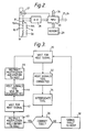
- Fig 2 shows more detail of part of the SCU 18, and Fig 3 shows the sequence of operations performed by the microprocessor 20.
- the microprocessor is waiting for a signal from the host computer.
- a signal is received from the host via the communication channel 26, advising the microprocessor that the host has caused the head 10 to pick up a tool 12 from a given location on the support 13 (in the manner described in the above-mentioned international patent application).
- the signal includes a code for identifying the tool concerned.
- the microprocessor interrogates the tool 12 which has been picked up.
- the microprocessor 20 takes the tool identification code received from the host at step 32 and addresses a table stored in its memory 29. From the table, it obtains a corresponding voltage value, being the value expected to be produced in the converter 28 by the tool which the host intended to be picked up. The microprocessor decides whether the correct tool has in fact been picked up by comparing this expected value with the value actually received in step 34. If the values do not agree (to within a specified tolerance) the microprocessor proceeds to step 38, where it signals a fault condition to the host. The host may then halt operation of the machine, or possibly it may attempt to correct the fault.
- Such a fault may occur for example, if the machine operator has placed the wrong tool in the chosen location of the support 13, or if the tool has not been successfully picked up for some reason. Signalling the fault in this way prevents the host from continuing its cycle with the wrong tool and possibly causing collision damage between the tool and the workpiece.
- the microprocessor sends the signal 21 to the multiplexer 22 to connect the corresponding interface 23 to the tool 12 (setp 40).
- the signal 24 is also sent to the appropriate interface to activate it. Prior to this time, no interface at all has been connected to the tool. This is important in order to ensure that the tool is not inadvertently connected to an incorrect power supply which could damage it. Having instructed the multiplexer and corresponding interface, the microprocessor confirms this fact to the host.
- the microprocessor then simply waits for a further signal from the host (step 42), during which time the host is controlling a measurement or inspection operation on the workpiece, using the selected tool 12.
- the host again signals the microprocessor 20 (step 44).
- the microprocessor then issues a signal 24 to disable the selected interface 23, and a signal 21 to cause the multiplexer 22 to disconnect the interface from the contacts 16A (step 46). Having done so, it confirms this fact to the host which will proceed to disconnect the tool from the head.
- the microprocessor can now return directly to step 30 to repeat the whole process for the next selected tool.
- Fig. 4 illustrates a further type of tool, one or more of which may be present in the support 13.
- This is an extension bar tool 50 which can be used as an accessory in conjunction with any one of the measuring tools 12.
- One end 52 of the bar is provided with mechanical and electrical connections identical with the tools 12, in order that it can be picked up by the head 10 (though the mechanical connections are not shown in the figure).
- the other end 54 has mechanical and electrical connections identical with the head 10, so that once the bar has been picked up by the head, it can then in turn pick up either a selected tool or another extension bar 50.
- the use of an extension bar is known per se, and enable the measuring tool 12 to inspect regions of the workpiece which would otherwise be inacessible, e.g. the internal surfaces of a bore. Often, to provide the greatest flexibility, several extension bars 50 of differing lengths will be stored in the support 13.
- a series of parallel electrical lines 15B, 16B run the length of the extension bar 50, connecting the contacts 15, 16 at the end 52 with the respective contacts 15A, 16A at the end 54. Additionally, it is desirable to be able to identify the extension bar or combination of bars which has been connected. To this end, each bar is provided with a unique-valued resistor 56 connected between one of the lines 15B and one of the lines 16B.
- the microprocessor 20 controls a switch 31 to connect the constant current source 27 and analogue-to-digital converter 28 across the corresponding contacts 15A, 16A.
- the identifying resistor 56 is interrogated in exactly the same way as described above for the resistor 19. If two or more extension bars 50 are connected in series, their resistors will appear in parallel to decrease the voltage measured by the analogue-to-digital converter.
- the combination of bars can be uniquely identified if the respective resistance values are suitable chosen: for example, so that the conductance of each bar is proportional to its length, or is in a binary sequence such as 100 ⁇ S, 200 ⁇ S, 400 ⁇ S, 800 ⁇ S etc.
- the resistor 56 is connected between a line 15B and a line 16B, rather than across the two lines 15B, in order to facilitate identification of the measurement tools 12 separately from the extension bar tools 50. Since this reduces the number of the electrical connections 16, 16A which are available for signal and power purposes, and since it is likely that the number of pins available for these purposes will be limited, it may be desirable to use the two connections 15, 15A for both identification functions. This can be done if the extensions bars (for example) are each identified with a unique capacitance value instead of a unique resistance value; but this leads to an excessively complicated arrangement and is not preferred.
- the tool change apparatus described is particularly useful with measuring and inspection tools on co-ordinate measuring machines, and can also be used with measuring and inspection tools on an automatic machine tool. It enables the correct interface to be selected and prevents electrical and mechanical damage being caused if the wrong tool is picked up. However, it is also useful for confirming the identity of tools not themselves intended for measurement or inspection, including the accessory extension bars already discussed, and even (if desired) the cutting tools of a machine tool, provided an appropriate resistor for identification can be applied to them.
Abstract
Description
- This invention relates to tool change apparatus, for example for changing the measuring tools used for inspection of workpieces on a co-ordinate measuring machine, or for a machine tool.
- An example of such a tool change apparatus is shown in our international patent application published under the number W085/02138. The apparatus exemplified by that application comprises a head for releasably supporting one of a plurality of tools. The tool may for example be a probe which generates a signal in response to contact with a workpiece. Such a signal is then transmitted via confronting electrical contacts on the tool and on the head to a computer (which may be part of the co-ordinate measuring machine or machine tool). Alternatively, GB-A-2141364 discloses infra-red signal transmission. In practice, an interface is commonly required to condition the signal before passing it to the computer, and/or also to provide appropriate power and possibly control signals to the tool.
- A problem arises where more than one type of tool is to be connected to the head, if different tools have different requirements for signal conditioning, power supply and/or control signals. The appropriate requirements for the tool currently connected must be met, and for example a tool may be damaged if an incorrect power supply is inadvertently applied to it. It is known from DE-A-1652694 and from EP-A-0132528 to provide identification means on a cutting tool for a machine tool, which can be read to identify the tool, but such cutting tools do not suffer from the above problem and therefore these two documents neither address that problem nor provide a solution to it.
- According to this invention we provide tool change apparatus comprising:
- (a) a tool-holding head having means for releasably supporting (in operation) one of a plurality of tools, the tools to be supported each including a respective identification resistance means having a resistance value unique to the tool, and
- (b) means for detecting the identity of a said tool, when supported by the head, from the resistance value of said resistance means of the tool, and for producing an output signal indicative of the identity.
- An embodiment of the invention will be described by way of example with reference to the accompanying drawings, in which:
- Fig 1 is a diagrammatic layout of a tool change apparatus,
- Fig 2 in a more detailed schematic diagram of part of the apparatus,
- Fig 3 is a flow chart explaining the operation of the apparatus, and
- Fig 4 shows diagrammatically an extension bar for use with the apparatus
- Referring to Fig 1, a co-ordinate measuring machine (known per se and not described in detail) has a
head 10 movable relative to a table 11 on which a plurality ofdifferent tools 12 are arranged in respective storage locations of asupport 13. Thehead 10 is adapted to be connected to any one of thetools 12 and to move the tool to a workpiece (not shown) for measuring or inspecting the workpiece all as known in general from our said International Patent Application. - The
tools 12 may include a probe, known per se, for sensing contact with a workpiece and opening electrical contacts within the probe when the workpiece is touched. They may also include analogue probes for responding to contact with the workpiece, proximity probes, crack detecting probes, laser and other optical measuring probes, video cameras etc. enabling the co-ordinate measuring machine to be used as a very flexible inspection system for inspecting a wide variety of quality aspects of the workpiece. - Each
tool 12 has anelectric circuit 14 connected to a plurality ofcontacts contacts head 10 to connect thetool circuit 14 to a signal conditioning unit ("SCU") 18 provided on thehead 10. Certain contacts, 15, are used to enable the SCU to recognise the particular tool being connected to thehead 10 while other contacts, 16, are used for transmitting an operational group ofsignals 17 to and from the tool. - For the purpose of said recognition, the
tools 12 includerespective resistors 19 of different resistance value connected to thecontacts 15. - The
SCU 18 of the present embodiment includes means (described below) for determining the resistance of the resistor of whatevertool 12 is connected to the head thereby to positively identify the tool. In this example a microprocessor system 20 (also described below) is used in the SCU for this purpose and is adapted to produce discrete identifyingsignals 21 for therespective tools 12. However, the same purpose could obviously be achieved by non-microprocessor circuity if preferred. - Said
other contacts 16 are connected through theSCU 18 to amultiplexer 22 for transmission of the operational signal groups from thetool 12 to arespective interface unit 23 where the operational signals are processed to appear at 25 in useful form for further processing by computer or for display e.g. in the form of printed characters. Theinterface 23 may also provide appropriate power and/or control signals to therespective tool 12 via the multiplexer. - The
multiplexer 22 is operated by the SCU in response to the identifyingsignals 21 so that the operational group ofsignals 17 of any onetool 12 identified by theSCU 18 is connected by themultiplexer 22 to theappropriate interface unit 23. TheSCU 18 is also adapted to producesignals 24 responsive to therespective signals 21 and connected to therespective interface units 23 to initiate the processing of theoperational signals 17 connected thereto by the multiplexer. Such processing may include the digitisation of analogue values. The SCU itself may include amplifiers for amplifying any such analogue values prior to onward transmission. Furthermore, themicroprocessor 20 is in communication via achannel 26 with a host computer of the co-ordinate measuring machine, which has overall control of the machine and governs the picking up, use and setting down of thetools 12 by thehead 10. - Fig 2 shows more detail of part of the
SCU 18, and Fig 3 shows the sequence of operations performed by themicroprocessor 20. Atstep 30 in Fig 3, the microprocessor is waiting for a signal from the host computer. At 32, a signal is received from the host via thecommunication channel 26, advising the microprocessor that the host has caused thehead 10 to pick up atool 12 from a given location on the support 13 (in the manner described in the above-mentioned international patent application). The signal includes a code for identifying the tool concerned. On receipt of this signal, atstep 34, the microprocessor interrogates thetool 12 which has been picked up. It does this by switching on a constantcurrent source 27 within the SCU, to pass a known constant current through theresistor 19 of the tool via thecontacts digital converter 28, indicating the voltage developed across theresistor 19 by the constant current. This input value, of course, is unique to the tool picked up. Having received the value, thecurrent source 27 is switched off. - Next, at
step 36, themicroprocessor 20 takes the tool identification code received from the host atstep 32 and addresses a table stored in itsmemory 29. From the table, it obtains a corresponding voltage value, being the value expected to be produced in theconverter 28 by the tool which the host intended to be picked up. The microprocessor decides whether the correct tool has in fact been picked up by comparing this expected value with the value actually received instep 34. If the values do not agree (to within a specified tolerance) the microprocessor proceeds tostep 38, where it signals a fault condition to the host. The host may then halt operation of the machine, or possibly it may attempt to correct the fault. Such a fault may occur for example, if the machine operator has placed the wrong tool in the chosen location of thesupport 13, or if the tool has not been successfully picked up for some reason. Signalling the fault in this way prevents the host from continuing its cycle with the wrong tool and possibly causing collision damage between the tool and the workpiece. - Assuming that the correct tool is identified, then the microprocessor sends the
signal 21 to themultiplexer 22 to connect thecorresponding interface 23 to the tool 12 (setp 40). Thesignal 24 is also sent to the appropriate interface to activate it. Prior to this time, no interface at all has been connected to the tool. This is important in order to ensure that the tool is not inadvertently connected to an incorrect power supply which could damage it. Having instructed the multiplexer and corresponding interface, the microprocessor confirms this fact to the host. - After this step, the microprocessor then simply waits for a further signal from the host (step 42), during which time the host is controlling a measurement or inspection operation on the workpiece, using the
selected tool 12. When this is completed on returning the tool to its storage location on thesupport 13 and immediately prior to disconnection of the tool from thehead 10, the host again signals the microprocessor 20 (step 44). The microprocessor then issues asignal 24 to disable theselected interface 23, and asignal 21 to cause themultiplexer 22 to disconnect the interface from thecontacts 16A (step 46). Having done so, it confirms this fact to the host which will proceed to disconnect the tool from the head. The microprocessor can now return directly tostep 30 to repeat the whole process for the next selected tool. - Fig. 4 illustrates a further type of tool, one or more of which may be present in the
support 13. This is anextension bar tool 50 which can be used as an accessory in conjunction with any one of themeasuring tools 12. Oneend 52 of the bar is provided with mechanical and electrical connections identical with thetools 12, in order that it can be picked up by the head 10 (though the mechanical connections are not shown in the figure). Theother end 54 has mechanical and electrical connections identical with thehead 10, so that once the bar has been picked up by the head, it can then in turn pick up either a selected tool or anotherextension bar 50. The use of an extension bar is known per se, and enable the measuringtool 12 to inspect regions of the workpiece which would otherwise be inacessible, e.g. the internal surfaces of a bore. Often, to provide the greatest flexibility, several extension bars 50 of differing lengths will be stored in thesupport 13. - To permit identification of the
tools 12 in exactly the same manner as above, and to allow for transmission of signals and power to and from the tool, a series of parallelelectrical lines extension bar 50, connecting thecontacts end 52 with therespective contacts end 54. Additionally, it is desirable to be able to identify the extension bar or combination of bars which has been connected. To this end, each bar is provided with a unique-valuedresistor 56 connected between one of thelines 15B and one of thelines 16B. Themicroprocessor 20 controls aswitch 31 to connect the constantcurrent source 27 and analogue-to-digital converter 28 across the correspondingcontacts resistor 56 is interrogated in exactly the same way as described above for theresistor 19. If two or more extension bars 50 are connected in series, their resistors will appear in parallel to decrease the voltage measured by the analogue-to-digital converter. The combination of bars can be uniquely identified if the respective resistance values are suitable chosen: for example, so that the conductance of each bar is proportional to its length, or is in a binary sequence such as 100µS, 200µS, 400µS, 800µS etc. - The
resistor 56 is connected between aline 15B and aline 16B, rather than across the twolines 15B, in order to facilitate identification of themeasurement tools 12 separately from theextension bar tools 50. Since this reduces the number of theelectrical connections connections - The tool change apparatus described is particularly useful with measuring and inspection tools on co-ordinate measuring machines, and can also be used with measuring and inspection tools on an automatic machine tool. It enables the correct interface to be selected and prevents electrical and mechanical damage being caused if the wrong tool is picked up. However, it is also useful for confirming the identity of tools not themselves intended for measurement or inspection, including the accessory extension bars already discussed, and even (if desired) the cutting tools of a machine tool, provided an appropriate resistor for identification can be applied to them.
Claims (13)
Applications Claiming Priority (2)
| Application Number | Priority Date | Filing Date | Title |
|---|---|---|---|
| GB8522984 | 1985-09-17 | ||
| GB858522984A GB8522984D0 (en) | 1985-09-17 | 1985-09-17 | Tool change apparatus |
Related Child Applications (1)
| Application Number | Title | Priority Date | Filing Date |
|---|---|---|---|
| EP90202139.3 Division-Into | 1990-08-07 |
Publications (2)
| Publication Number | Publication Date |
|---|---|
| EP0236414A1 EP0236414A1 (en) | 1987-09-16 |
| EP0236414B1 true EP0236414B1 (en) | 1991-05-08 |
Family
ID=10585308
Family Applications (2)
| Application Number | Title | Priority Date | Filing Date |
|---|---|---|---|
| EP19900202139 Expired EP0404275B1 (en) | 1985-09-17 | 1986-09-17 | Exchangeable tools |
| EP86905372A Expired - Lifetime EP0236414B1 (en) | 1985-09-17 | 1986-09-17 | Tool change apparatus |
Family Applications Before (1)
| Application Number | Title | Priority Date | Filing Date |
|---|---|---|---|
| EP19900202139 Expired EP0404275B1 (en) | 1985-09-17 | 1986-09-17 | Exchangeable tools |
Country Status (5)
| Country | Link |
|---|---|
| EP (2) | EP0404275B1 (en) |
| JP (1) | JPS62502569A (en) |
| DE (2) | DE3679177D1 (en) |
| GB (1) | GB8522984D0 (en) |
| WO (1) | WO1987001798A1 (en) |
Cited By (3)
| Publication number | Priority date | Publication date | Assignee | Title |
|---|---|---|---|---|
| WO2003002296A1 (en) * | 2001-06-28 | 2003-01-09 | Renishaw Plc | Tool identification |
| US11175131B2 (en) | 2017-06-30 | 2021-11-16 | Mitutoyo Corporation | Self-configuring component identification and signal processing system for a coordinate measurement machine |
| US11426257B2 (en) * | 2017-05-12 | 2022-08-30 | Cyber Surgery, S.L. | Self-identifying surgical clamp, fiducial element for use with such a clamp and kits comprising such clamps and fiducial elements |
Families Citing this family (31)
| Publication number | Priority date | Publication date | Assignee | Title |
|---|---|---|---|---|
| DE3823373A1 (en) * | 1988-07-09 | 1990-01-11 | Zeiss Carl Fa | METHOD FOR DETECTING THE TEMPERATURE OF MEASURING OBJECTS ON COORDINATE MEASURING DEVICES |
| DE3834117A1 (en) * | 1988-10-07 | 1990-04-12 | Zeiss Carl Fa | COORDINATE MEASURING DEVICE WITH AN OPTICAL PROBE |
| DE8813875U1 (en) * | 1988-11-05 | 1988-12-22 | Fa. Carl Zeiss, 7920 Heidenheim, De | |
| DE3919699A1 (en) * | 1989-06-16 | 1991-01-03 | Isleib Hans Gerd | TOOL IDENTIFICATION |
| US5208436A (en) * | 1991-04-12 | 1993-05-04 | The Lincoln Electric Company | Plasma torch with identification circuit |
| US5611147A (en) * | 1993-02-23 | 1997-03-18 | Faro Technologies, Inc. | Three dimensional coordinate measuring apparatus |
| DE4330873A1 (en) * | 1993-09-13 | 1995-03-16 | Zeiss Carl Fa | Coordinate measuring device with a probe and electronics for processing the probe signal |
| AU7121094A (en) * | 1994-06-14 | 1996-01-05 | Dansk Industri Syndikat A/S | Method and arrangement for identifying tools in a moulding machine |
| DE19531843A1 (en) * | 1995-08-29 | 1997-03-13 | Hubert Niemann | Procedure for determining the cut dimensions for tops |
| DE19543763B4 (en) * | 1995-11-24 | 2005-07-21 | Leitz Messtechnik Gmbh | Method for automatically detecting different sensors in coordinate measuring machines and devices for carrying out the method |
| DE19631425A1 (en) * | 1996-08-06 | 1998-02-12 | Wolf & Beck Gmbh Dr | Identification method for interchangeable accessories of machines tools |
| DE19722121A1 (en) * | 1997-05-27 | 1998-12-03 | Wendt Gmbh | Device for the identification and automatic identification and classification of tools |
| US5953687A (en) * | 1997-08-18 | 1999-09-14 | Giddings & Lewis, Inc. | Method and apparatus for displaying active probe tip status of a coordinate measuring machine |
| US6536268B1 (en) * | 1999-11-01 | 2003-03-25 | Siemens Vdo Automotive Corporation | Utilizing increasing width for identification voltages |
| FR2803978A1 (en) * | 2000-01-17 | 2001-07-20 | Air Liquide | PLASMA TORCH WITH HEAD, ELECTRODE OR TIPE IDENTIFICATION SYSTEM |
| US6629048B1 (en) * | 2000-11-20 | 2003-09-30 | Tektronix, Inc. | Measurement test instrument and associated voltage management system for accessory device |
| DE10209288B4 (en) * | 2002-03-01 | 2005-04-28 | Rittal Gmbh & Co Kg | Control cabinet monitoring and control system |
| US6829547B2 (en) * | 2002-04-29 | 2004-12-07 | Tektronix, Inc. | Measurement test instrument and associated voltage management system for accessory device |
| DE202004011364U1 (en) * | 2004-07-20 | 2004-09-09 | Klingelnberg Gmbh | Device for recognizing a measuring head used on a measuring device |
| DE102004048095A1 (en) * | 2004-09-30 | 2006-04-06 | Carl Zeiss Industrielle Messtechnik Gmbh | Stylus and stylus replacement holder for a coordinate measuring machine |
| DE102006024904B4 (en) * | 2006-05-24 | 2012-10-25 | Franz Klaiber | A method of providing tools for making and / or processing objects, wherein identifiers are associated with the tools and locations |
| CN101511529B (en) | 2006-08-31 | 2013-01-30 | 法罗技术股份有限公司 | Method capable of removing smart probea and combination system, and using coordinate measuring machine |
| WO2008126112A1 (en) * | 2007-04-12 | 2008-10-23 | C.O.B.O. S.P.A. | Device and method to control operating machines |
| DE102007021362A1 (en) * | 2007-05-04 | 2008-11-06 | Carl Zeiss Industrielle Messtechnik Gmbh | Identification of interchangeable coordinate measuring equipment |
| DE102010031976A1 (en) | 2010-07-22 | 2012-01-26 | Carl Zeiss Industrielle Messtechnik Gmbh | Determination of the coupling of parts to a machine |
| JP5843531B2 (en) | 2010-09-27 | 2016-01-13 | 株式会社ミツトヨ | Coordinate measuring head unit and coordinate measuring machine |
| WO2013091697A1 (en) * | 2011-12-21 | 2013-06-27 | Carl Zeiss Industrielle Messtechnik Gmbh | Method for coupling two system components of a measuring device, in particular a co-ordinate measuring device |
| DE102015119440A1 (en) | 2015-09-18 | 2017-03-23 | Werth Messtechnik Gmbh | Method and device for detecting interchangeable components present on a coordinate measuring machine, such as sensor head |
| JP6491698B2 (en) | 2017-06-23 | 2019-03-27 | 株式会社ミツトヨ | Three-dimensional measurement unit and measuring probe identification method |
| DE102017118313A1 (en) * | 2017-08-11 | 2019-02-14 | M & H Inprocess Messtechnik Gmbh | Measuring system set |
| JP6568167B2 (en) * | 2017-08-25 | 2019-08-28 | ファナック株式会社 | Anomaly detection device and machine learning device |
Family Cites Families (8)
| Publication number | Priority date | Publication date | Assignee | Title |
|---|---|---|---|---|
| DE1652694A1 (en) * | 1968-02-13 | 1971-02-25 | Hermann Kolb Maschinenfabrik | Machine tool with automatic tool changing device |
| US3823466A (en) * | 1970-04-22 | 1974-07-16 | Devlieg Machine Co | Machine tool with automatic tool changing mechanism |
| JPS4886181A (en) * | 1972-02-18 | 1973-11-14 | ||
| JPS5890113A (en) * | 1981-11-25 | 1983-05-28 | Yamazaki Mazak Corp | Establishment control of coordinate system at machining center |
| JPS58173425A (en) * | 1982-04-06 | 1983-10-12 | Mitsutoyo Mfg Co Ltd | Three-dimensional measuring machine |
| US4509266A (en) * | 1982-06-14 | 1985-04-09 | Gte Valeron Corporation | Touch probe |
| DE3326615A1 (en) * | 1983-07-23 | 1985-01-31 | Otto Bilz, Werkzeugfabrik, 7302 Ostfildern | TOOL OR TOOL HOLDER, IN PARTICULAR FOR CUTTING MACHINING ON NUMERICALLY CONTROLLED MACHINING CENTERS |
| GB8330412D0 (en) * | 1983-11-15 | 1983-12-21 | Renishaw Plc | Tool change apparatus |
-
1985
- 1985-09-17 GB GB858522984A patent/GB8522984D0/en active Pending
-
1986
- 1986-09-17 DE DE8686905372T patent/DE3679177D1/en not_active Expired - Fee Related
- 1986-09-17 DE DE9090202139T patent/DE3682212D1/en not_active Expired - Fee Related
- 1986-09-17 EP EP19900202139 patent/EP0404275B1/en not_active Expired
- 1986-09-17 WO PCT/GB1986/000551 patent/WO1987001798A1/en active IP Right Grant
- 1986-09-17 JP JP50489886A patent/JPS62502569A/en active Granted
- 1986-09-17 EP EP86905372A patent/EP0236414B1/en not_active Expired - Lifetime
Non-Patent Citations (2)
| Title |
|---|
| IEEE Standard dictionary of Electrical & Electronics terms, 2nd Edition, page 430 * |
| The new Penguin dictionary of Electronics, page 334 * |
Cited By (5)
| Publication number | Priority date | Publication date | Assignee | Title |
|---|---|---|---|---|
| WO2003002296A1 (en) * | 2001-06-28 | 2003-01-09 | Renishaw Plc | Tool identification |
| US7096077B2 (en) | 2001-06-28 | 2006-08-22 | Renishaw Plc | Tool identification |
| US11426257B2 (en) * | 2017-05-12 | 2022-08-30 | Cyber Surgery, S.L. | Self-identifying surgical clamp, fiducial element for use with such a clamp and kits comprising such clamps and fiducial elements |
| IL270546B1 (en) * | 2017-05-12 | 2023-09-01 | Cyber Surgery S L | Self-identifying surgical clamp, fiducial element for use with such a clamp and kits comprising such clamps and fiducial elements |
| US11175131B2 (en) | 2017-06-30 | 2021-11-16 | Mitutoyo Corporation | Self-configuring component identification and signal processing system for a coordinate measurement machine |
Also Published As
| Publication number | Publication date |
|---|---|
| GB8522984D0 (en) | 1985-10-23 |
| DE3682212D1 (en) | 1991-11-28 |
| JPS62502569A (en) | 1987-10-01 |
| JPH0525282B2 (en) | 1993-04-12 |
| WO1987001798A1 (en) | 1987-03-26 |
| DE3679177D1 (en) | 1991-06-13 |
| EP0236414A1 (en) | 1987-09-16 |
| EP0404275B1 (en) | 1991-10-23 |
| EP0404275A1 (en) | 1990-12-27 |
Similar Documents
| Publication | Publication Date | Title |
|---|---|---|
| EP0236414B1 (en) | Tool change apparatus | |
| EP1401612B1 (en) | Tool identification | |
| US4895454A (en) | Method of determining the temperature of a workpiece in a flexible manufacturing system | |
| EP0116553B1 (en) | Method and apparatus for bus fault location | |
| KR20020001752A (en) | Tester and testing method, and testing unit | |
| EP0352683B1 (en) | Programmable controller module identification system | |
| US4956786A (en) | Marking or engraving machine | |
| EP3418683A1 (en) | Coordinate measuring unit and method for recognizing measuring probe | |
| US6618629B2 (en) | Communications interface for assembly-line monitoring and control | |
| KR100295249B1 (en) | Ic testing apparatus | |
| CA2060419A1 (en) | Multiple adapter response detection circuit | |
| JPH0886822A (en) | Wire harness inspection instrument | |
| JP2978774B2 (en) | Radio inspection equipment | |
| JPH10115653A (en) | Conduction inspection device and inspection method thereof and its inspection probe | |
| KR100190661B1 (en) | Automatic deflecting apparatus to detect a class of deflection yoke | |
| JP2000510625A (en) | Bus system and method for diagnosing a plurality of subscribers interconnected via the bus system | |
| JPS60123091A (en) | Printed board mounting device | |
| JPH06246569A (en) | Control device for printed circuit board boring machine | |
| KR100193442B1 (en) | How to check the wire harness | |
| JPH07244105A (en) | Bridged solder detecting method by board inspecting device for mounting board | |
| JP4508468B2 (en) | Relay unit structure in control equipment | |
| JP2808966B2 (en) | Prober | |
| KR100642127B1 (en) | Voltage Control Unit of Printed Circuit Board and Method | |
| JP4585717B2 (en) | Component mounting error detection apparatus and detection method for electronic component mounting machine | |
| JPH05333102A (en) | Ic handling device |
Legal Events
| Date | Code | Title | Description |
|---|---|---|---|
| PUAI | Public reference made under article 153(3) epc to a published international application that has entered the european phase |
Free format text: ORIGINAL CODE: 0009012 |
|
| 17P | Request for examination filed |
Effective date: 19870506 |
|
| AK | Designated contracting states |
Kind code of ref document: A1 Designated state(s): CH DE FR GB IT LI SE |
|
| 17Q | First examination report despatched |
Effective date: 19890220 |
|
| RAP3 | Party data changed (applicant data changed or rights of an application transferred) |
Owner name: RENISHAW PLC |
|
| GRAA | (expected) grant |
Free format text: ORIGINAL CODE: 0009210 |
|
| AK | Designated contracting states |
Kind code of ref document: B1 Designated state(s): CH DE FR GB IT LI SE |
|
| ITF | It: translation for a ep patent filed |
Owner name: BARZANO' E ZANARDO MILANO S.P.A. |
|
| XX | Miscellaneous (additional remarks) |
Free format text: TEILANMELDUNG 90202139.3 EINGEREICHT AM 17/09/86. |
|
| REF | Corresponds to: |
Ref document number: 3679177 Country of ref document: DE Date of ref document: 19910613 |
|
| PGFP | Annual fee paid to national office [announced via postgrant information from national office to epo] |
Ref country code: FR Payment date: 19910812 Year of fee payment: 6 |
|
| PGFP | Annual fee paid to national office [announced via postgrant information from national office to epo] |
Ref country code: SE Payment date: 19910816 Year of fee payment: 6 |
|
| PGFP | Annual fee paid to national office [announced via postgrant information from national office to epo] |
Ref country code: CH Payment date: 19910819 Year of fee payment: 6 |
|
| ET | Fr: translation filed | ||
| PLBE | No opposition filed within time limit |
Free format text: ORIGINAL CODE: 0009261 |
|
| STAA | Information on the status of an ep patent application or granted ep patent |
Free format text: STATUS: NO OPPOSITION FILED WITHIN TIME LIMIT |
|
| 26N | No opposition filed | ||
| PG25 | Lapsed in a contracting state [announced via postgrant information from national office to epo] |
Ref country code: SE Effective date: 19920918 |
|
| PG25 | Lapsed in a contracting state [announced via postgrant information from national office to epo] |
Ref country code: LI Effective date: 19920930 Ref country code: CH Effective date: 19920930 |
|
| PG25 | Lapsed in a contracting state [announced via postgrant information from national office to epo] |
Ref country code: FR Effective date: 19930528 |
|
| REG | Reference to a national code |
Ref country code: CH Ref legal event code: PL |
|
| REG | Reference to a national code |
Ref country code: FR Ref legal event code: ST |
|
| EUG | Se: european patent has lapsed |
Ref document number: 86905372.8 Effective date: 19930406 |
|
| PGFP | Annual fee paid to national office [announced via postgrant information from national office to epo] |
Ref country code: GB Payment date: 19960820 Year of fee payment: 11 |
|
| PGFP | Annual fee paid to national office [announced via postgrant information from national office to epo] |
Ref country code: DE Payment date: 19960826 Year of fee payment: 11 |
|
| PG25 | Lapsed in a contracting state [announced via postgrant information from national office to epo] |
Ref country code: GB Free format text: LAPSE BECAUSE OF NON-PAYMENT OF DUE FEES Effective date: 19970917 |
|
| GBPC | Gb: european patent ceased through non-payment of renewal fee |
Effective date: 19970917 |
|
| PG25 | Lapsed in a contracting state [announced via postgrant information from national office to epo] |
Ref country code: DE Free format text: LAPSE BECAUSE OF NON-PAYMENT OF DUE FEES Effective date: 19980603 |
|
| PG25 | Lapsed in a contracting state [announced via postgrant information from national office to epo] |
Ref country code: IT Free format text: LAPSE BECAUSE OF NON-PAYMENT OF DUE FEES Effective date: 20050917 |