EP0235662B1 - Optischer Sender mit einem optischen Frequenzdiskriminator - Google Patents
Optischer Sender mit einem optischen Frequenzdiskriminator Download PDFInfo
- Publication number
- EP0235662B1 EP0235662B1 EP87102199A EP87102199A EP0235662B1 EP 0235662 B1 EP0235662 B1 EP 0235662B1 EP 87102199 A EP87102199 A EP 87102199A EP 87102199 A EP87102199 A EP 87102199A EP 0235662 B1 EP0235662 B1 EP 0235662B1
- Authority
- EP
- European Patent Office
- Prior art keywords
- optical
- frequency
- intensity
- mark
- modulated
- Prior art date
- Legal status (The legal status is an assumption and is not a legal conclusion. Google has not performed a legal analysis and makes no representation as to the accuracy of the status listed.)
- Expired - Lifetime
Links
Images


Classifications
-
- H—ELECTRICITY
- H04—ELECTRIC COMMUNICATION TECHNIQUE
- H04B—TRANSMISSION
- H04B10/00—Transmission systems employing electromagnetic waves other than radio-waves, e.g. infrared, visible or ultraviolet light, or employing corpuscular radiation, e.g. quantum communication
- H04B10/50—Transmitters
- H04B10/501—Structural aspects
- H04B10/503—Laser transmitters
- H04B10/504—Laser transmitters using direct modulation
-
- H—ELECTRICITY
- H04—ELECTRIC COMMUNICATION TECHNIQUE
- H04B—TRANSMISSION
- H04B10/00—Transmission systems employing electromagnetic waves other than radio-waves, e.g. infrared, visible or ultraviolet light, or employing corpuscular radiation, e.g. quantum communication
- H04B10/50—Transmitters
- H04B10/516—Details of coding or modulation
- H04B10/54—Intensity modulation
- H04B10/541—Digital intensity or amplitude modulation
-
- H—ELECTRICITY
- H04—ELECTRIC COMMUNICATION TECHNIQUE
- H04B—TRANSMISSION
- H04B10/00—Transmission systems employing electromagnetic waves other than radio-waves, e.g. infrared, visible or ultraviolet light, or employing corpuscular radiation, e.g. quantum communication
- H04B10/50—Transmitters
- H04B10/516—Details of coding or modulation
- H04B10/548—Phase or frequency modulation
Definitions
- This invention relates to an optical transmitter which is for use in an optical communication network and comprises a directly modulated semiconductor laser.
- optical communication electric signals are ordinarily transmitted as an optical beam representative of mark and space codes.
- the semiconductor laser is supplied with a modulated injection current to produce an intensity modulated optical signal as the optical beam.
- the semiconductor laser is preliminarily supplied with a d.c. bias current of a level which is near to the oscillation threshold level of the semiconductor laser.
- An electric pulse current representative of the mark and the space codes is superimposed on the d.c. bias current to provide the modulated injection current.
- the optical beam has a high intensity for each mark code and a low intensity for each space code. At any rate, a ratio of the high intensity to the low intensity is called an extinction ratio.
- US-A-4,561,119 discloses an optical frequency modulation system according to the preamble of claim 1.
- FR-A-2538195 discloses a similar optical communication system without an indication of the light source which may be coherent or non-coherent.
- an optical transmitter is for use in an optical communication network and comprises a semiconductor laser 11 according to a first embodiment of the present invention.
- the semiconductor laser 11 has a certain oscillation threshold level and is directly modulated. More particularly, the semiconductor laser 11 is supplied with a d.c. bias current from a d.c. source 12 through an adder 13.
- the d.c. bias current is given a level which is a little higher than the oscillation threshold level.
- a signal source 14 is for producing an electric pulse current representative of mark and space codes.
- the adder 13 is for superimposing the electric pulse current on the d.c. bias current to supply an adder output signal to the semiconductor laser 11 as a modulating injection current.
- the semiconductor laser 11 generates an optical signal which includes a frequency modulated component in the manner discribed in an article which was contributed by Soichi Kobayashi et al to IEEE Journal of Quantum Electronics, Volume QE-18. Number 4 (April 1982), pages 582 to 595 and entitled "Direct Frequency Modulation in AlGaAs Semiconductor Lasers.”
- the optical signal is linearly polarized and is delivered to a Mach-Zehnder interferometer 15 which is used as an optical frequency discriminator. More particularly, the optical signal is equally divided by a first semitransparent mirror 16 into first and second parts. The first part is led directly to a second semitransparent mirror 17. The second part is led to the second semitransparent mirror 17 through first and second mirrors 18 and 19 which are placed nearer to the first and the second semitransparent mirrors 16 and 17. In this manner, the first part reaches the second semitransparent mirror 17 through a first or direct optical path 21. The second part reaches the second semitransparent mirror 17 through a second or broken-line optical path 22.
- the second semitransparent mirror 17 Depending on a path difference between the first and the second optical paths 21 and 22, the second semitransparent mirror 17 produces first and second intensity modulated optical signals which travel substantially along the first optical path 21 and along an optical path from the second mirror 19 to the second semitransparent mirror 17.
- the first intensity modulated optical signal is delivered from the second semitransparent mirror 17 to an optical fiber 25 of the optical communication network as an output optical beam.
- the optical transmitter includes the semiconductor laser 11 responsive to the modulated injection current for generating the optical signal which includes a frequency modulated component.
- the optical frequency discriminator (15) is used to convert the frequency modulated component to an intensity modulated component and to produce the optical output beam which consists essentially of the intensity modulated component.
- the optical signal of the semiconductor laser 11 is linearly polarized, it is unnecessary to control polarization of the first and the second parts which travel along the optical frequency discriminator and are subjected to interference at the second semitransparent mirror 17.
- the oscillation threshold level of the semiconductor laser 11 was 20 mA.
- the semiconductor laser 11 was for generating the optical signal at a wavelength range of 1.5 microns in the single axial or longitudinal mode.
- the signal source 14 was for, the electric pulse current of a bit rate of 1 Gb/s.
- the injection current had an instantaneous current value I which had a first current value I1 of 50 mA for each mark code and a second current value I2 of 30 mA for each space code.
- the frequency modulated component has a first or lower frequency F1 for each mark code and a second or higher frequency F2 for each space code.
- the first and the second frequencies F1 and F2 had a frequency difference of about 20 GHz.
- the semiconductor laser 11 was stably operable even at the high bit rate of 1 Go/s without chirping.
- the current value I and the frequency F are interrelated by a characteristic curve of a positive or a negative slope depending on the bit rate at which the semiconductor laser 11 is driven.
- the Mach-Zehnder interferometer 15 has a path difference of about 7.5 mm between the first and the second optical paths 21 and 22. In the manner exemplified in Fig. 3, the path difference is for discriminating between the first and the second frequencies F1 and F2. More specifically, the Mach-Zehnder interferometer 15 has a transmissivity T which varies between a first transmissivity of unity for the first frequency F1 and a second transmissivity of zero for the second frequency F2. In practice, the path difference was minutely adjusted so as to make the Mach-Zehnder interferometer 15 have the second transmissivity of substantially zero for the second frequency F2.
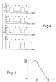
- FIG. 4 operation will be described as regards a typical optical transmitter of the type illustrated with reference to Fig. 1.
- Time t is shown along the abscissa of each figure part of Fig. 4.
- Each mark code is represented by "1" and each space code, by "0".
- the current value I of the electric pulse current varies between the first and the second current values I1 and I2.
- the semiconductor laser 11 generates the optical signal with an intensity level L which varies between a high level for each mark code and a low level for each space code.
- the frequency F of the optical signal varies between the first or lower frequency F1 and the second or higher frequency F2 for the mark and the space codes.
- the Mach-Zehnder interferometer 15 produces the output optical beam with an intensity or power P which varies between a high intensity for each mark code and a low intensity of substantially zero for each space code.
- the Mach-Zehnder interferometer 15 inevitably gives rise to jitter in leading and trailing edges of a pulse waveform of the optical output beam due to the path difference.
- the jitter was, however, less than 25 picoseconds and was negligible at the bit rate of 1 Gb/s.
- the high intensity of the optical output beam was at least 90°/o of the high level of the optical signal which was generated by the semiconductor laser 11 and supplied to the Mach-Zehnder interferometer 15.
- the output optical beam had an astonishingly high extinction ratio of 1 : 100 where the extinction ratio is a ratio of the low level or intensity to the high level or intensity.
- the optical output beam had an intensity difference which is 1.4 times a level difference between the high and the low levels of the optical signal.
- the optical transmitter comprises similar parts which are designated by like reference numerals.
- the d.c. source 12, the adder 13, and the signal source 14 of Fig. 1 are collectively depicted as a modulating signal source 26.
- the semiconductor laser 11 is accompanied by a temperature controller 27.
- the semiconductor laser 11 had an oscillation threshold level of 20 mA and was directly modulated by the injection current which was produced by the modulating signal source 26 to represent the mark and the space codes.
- the semiconductor laser 11 was for generating the optical signal which had a frequency difference of about 20 GHz between the first or lower frequency F1 for each mark code and a second or higher frequency F2 for each space code.
- the Mach-Zehnder interferometer 15 or a similar optical frequency discriminator has a frequency discrimination characteristic which also fluctuates due to mechanical shocks or other external disturbances, It is therefore very disirable to prevent the extinction ratio from degrading as a result of such external disturbances,
- the semiconductor laser 11 supplies the Mach-Zehnder interferometer 15 with the optical signal of a first power P1 for each mark code and a second power P2 for each space code.
- the first transmissivity undergoes a first-order small variation in the direction with sense of the shift.
- the second transmissivity always becomes greater than zero by a second-order small value.
- the first transmissivity of the Mach-Zehnder interferometer 15 (Fig. 5) is set at 0.9 or 90°/o for the first frequency F1 of the optical signal supplied thereto from the semiconductor laser 11.
- the first and the second optical paths 21 and 22 are made to have a path difference of about 6.0 mm.
- the Mach-Zehnder interferometer 15 is capable of discriminating a frequency difference of 25 GHz which is wider than the frequency difference of 20 GHz between the first and the second frequencies F1 and F2 of the optical signal.
- the path difference was minutely adjusted so as to render the second transmissivity substantially equal to zero for the second frequency F2.
- the first intensity modulated optical signal is delivered from the Mach-Zehnder interferometer 15 to the optical fiber 25 of the optical communication network in the manner described earlier.
- the second intensity modulated optical signal is supplied to an optical detector or photodetector 31 which is for producing an electric signal of a variable voltage representative of the average power of the second intensity modulated optical signal and consequently of the output optical beam.
- a reference voltage source 32 is for generating a reference voltage representative of the optimum power Po.
- a differential amplifier 33 delivers a control signal to the temperatur controller 27.
- the control signal has a zero voltage and is used in making the semiconductor laser 11 generate the optical signal variable between the first and the second frequencies F1 and F2 which are for rendering the average power equal to the optimum power Po.
- variable voltage represents the fluctuating power Pf in general.
- the control signal is used to raise the frequency F of the optical signal as by reducing the temperature of the semiconductor laser 11.
- the control signal is used to reduce the frequency F of the optical signal.
- a combination of the reference voltage source 32 and the differential amplifier 33 serves as a negative feedback circuit for the semiconductor laser 11.
- the negative feedback circuit is used so as to keep the extinction ratio substantially at an optimum value.
- the first transmissivity is equal to 0.9
- the high intensity of the output optical beam was only 0.5 dB less than the high level of the optical signal.
- the intensity difference of the output optical beam was 1.3 times the level difference of the optical signal.
- the extinction ratio was kept substantially at 1 : 100.
- phase adjuster 34 is interposed in the first optical path 21 of the Mach-Zehnder interferometer 15 between the first and the second semitransparent mirrors 16 and 17 for the purpose which will shortly become clear.
- the phase adjuster 34 may be a crystal of lithium niobate (LiNbO3) which has an effective optical length variable with a control voltage supplied across the crystal.
- the phase adjuster 34 may be a piezoelectric crystal which is supplied with a control voltage to have a variable refractive index.
- the second intensity modulated optical signal is supplied from the Mach-Zehnder interferometer 15 to the optical detector 31.
- the control signal of the differential amplifier 33 is used to provide the control voltage for the phase adjuster 34.
- the control signal is used to reduce the effective optical length. This shifts the frequency discrimination characteristic of the Mach-Zehnder interferometer 15 towards a higher frequency region.
- the control signal is used in shifting the frequency discrimination characteristic towards a lower frequency region by lengthening the effective optical length. It has been confirmed that the extinction ratio is kept substantially at the optimum value even when the negative feedback circuit is used in this manner to control the Mach-Zehnder interferometer 15.
- FIG. 8 Similar parts are designated by like reference numerals in an optical transmitter according to a fourth embodiment of this invention.
- a diffraction grating 35 is used in place of the Mach-Zehnder interferometer 15 described heretobefore.
- First and second slits 36 and 37 are coupled to the diffraction grating 35. In this manner, the diffraction grating 35 serves as an optical frequency discriminator.
- the first slit 36 is for directing a first intensity modulated optical signal to an optical coupler 38 and thence to the optical fiber 25 of the optical communication network as the output optical beam.
- the second slit 37 is for supplying a second intensity modulated optical signal to the optical detector 31.
- the control signal is delivered from the differential amplifier 33 to the modulating signal source 26 and is used in controlling the semiconductor laser 11 by adjusting the injection current.
- the second intensity modulated optical signal has a power which varies complementarily in relation to the first intensity modulated optical signal. It is nevertheless possible to use the negative feedback circuit in keeping the extinction ratio substantially at the optimum value.
- the second slit 37 has a width which is narrower than the first slit 36.
- the negative feedback circuit is used to control only one of the semiconductor laser 11 and the optical frequency discriminator which may either be the Mach-Zehnder interferometer 15 or the diffraction grating 35. It will readily be appreciated that the negative feedback circuit can be used in controlling whichever of the semiconductor laser 11 and the optical frequency discriminator 15 or 35 so as to compensate for the fluctuations which might result from the semicondustor laser 11 and/or the optical frequency discriminator 15 or 35 subjected to external disturbances.
- a Fabry-Perot interferometer or a Michelson interferometer can be substituted for the Mach-Zehnder interferometer 15.
- Such an interferometer can be implemented either by integrated-optics or by fiber-optics.
- the diffraction grating 35 may be a reflecting grating or a concave grating.
Landscapes
- Physics & Mathematics (AREA)
- Electromagnetism (AREA)
- Engineering & Computer Science (AREA)
- Computer Networks & Wireless Communication (AREA)
- Signal Processing (AREA)
- Optics & Photonics (AREA)
- Optical Communication System (AREA)
- Semiconductor Lasers (AREA)
Claims (9)
- Optischer Sender mit:a) einem Halbleiterlaser (11), der auf einen modulierten Injektionsstrom reagiert, um ein optisches Signal zu erzeugen, das eine frequenzmodulierte Komponente enthält; undb) einem optischen Frequenzdiskriminator (15), der auf das optische Signal reagiert, um die frequenzmodulierte Komponente in eine intensitätsmodulierte Komponente umzuwandeln, um einen optischen Ausgangsstrahl zu erzeugen, der die intensitätsmodulierte Komponente aufweist,dadurch gekennzeichnet, daß der Halbleiterlaser eine Einfach-Axial-Modus-Laserdiode (11) ist.
- Optischer Sender nach Anspruch 1, dadurch gekennzeichnet, daß der modulierte Injektionsstrom Zeichen/Pausecodes darstellt, und der optische Ausgangsstrahl eine hohe und eine niedrige Intensität aufweist, wenn der modulierte Injektionsstrom jeweils den einen oder anderen Zeichencode oder Pausencode darstellt.
- Optischer Sender nach Anspruch 2 der weiter aufweist:
eine Überwachungseinrichtung (38) zur Überwachung des optischen Ausgangsstrahls, um ein elektrisches Signal zu erzeugen, das ein Verhältnis der niedrigen Intensität zur hohen Intensität darstellt; und
eine negative Rückkopplungsschaltung (32, 33), die auf das elektrische Signal reagiert, um mindestens entweder die Laserdiode (11) oder den optischen Frequenzdiskriminator (15) zu steuern, um das Verhältnis auf einem optimalen Wert zu halten. - Optischer Sender nach Anspruch 3, wobei die frequenzmodulierte Komponente eine erste und eine zweite Frequenz aufweist, wenn der modulierte Injektionsstrom jeweils den einen oder den anderen von den Zeichen- und den Pausencodes darstellt, wobei dem optischen Frequenzdiskriminator durch den optimalen Wert ein erster Transmissionsgrad von mindestens 90 % für die frequenzmodulierte Komponente der ersten Frequenz und ein zweiter Transmissionsgrad von Null für die frequenzmodulierte Komponente der zweiten Frequenz verliehen wird.
- Optischer Sender nach Anspruch 3 oder 4, wobei der optische Frequenzdiskriminator dazu dient, um desweiteren einen zusätzlichen optischen Strahl mit einer höheren Intensität für den einen von den Zeichen/Pausecodes als für den anderen von den Zeichen/Pausecodes zu erzeugen, wobei die Überwachungsvorrichtung einen optischen Detektor (31) für den Empfang des zusätzlichen optischen Strahls aufweist, um damit den optischen Ausgangsstrahl zu überwachen, um das elektrische Signal zu erzeugen.
- Optischer Sender nach Anspruch 3, 4 oder 5, wobei der optische Frequenzdiskriminator ein optisches Interferometer aufweist, vorzugsweise ein Mach-Zehnder-Interferometer (15).
- Optischer Sender nach Anspruch 6, wobei die erste frequenzmodulierte Komponente eine erste und eine zweite Frequenz aufweist, wenn der modulierte Injektionsstrom den einen bzw. den anderen von den Zeichen/Pausecodes darstellt, wobei die negative Rückkopplungsschaltung (32, 33) der Steuerung der Laserdiode (11) und/oder des Mach-Zehnder-Interferometers (15) dient, um so dem Mach-Zehnder-Interferometer (15) einen ersten Transmissionsgrad von mindestens 90 % für die frequenzmodulierte Komponente der ersten Frequenz und einen zweiten Transmissionsgrad von Null für die frequenzmodulierte Komponente der zweiten Frequenz zu verleihen.
- Optischer Sender nach Anspruch 7, wobei das optische Signal in dem Mach-Zehnder-Interferometer (15) jeweils einen ersten und zweiten Teilstrahl mit einem ersten (21) bzw. einem zweiten (22) optischen Pfad aufweist, und wobei den ersten und zweiten optischen Pfaden (21 bzw. 22) eine Pfadlängendifferenz von 6 oder 7,5 mm verliehen ist, wenn das optische Signal eine Wellenlänge von 1,5 µm aufweist, und diese so abgestimmt ist, daß der zweite Transmissionsgrad Null wird.
- Optischer Sender nach einem der Ansprüche 1 bis 8, wobei der optische Frequenzdiskriminator aufweist:
ein Beugungsgitter (35) zur Beugung des optischen Signals in einen gebeugten Strahl;
einen ersten Spalt (36), um aus dem gebeugten Strahl den optischen Ausgangsstrahl zu erzeugen;
und einen zweiten Spalt (37), um aus dem gebeugten Strahl einen zusätzlichen optischen Strahl zu erzeugen; und
der optische Sender aufweist:
eine Überwachungsvorrichtung (31) zum Empfang des zusätzlichen optischen Strahls, um damit den optischen Ausgangsstrahl zu überwachen und ein elektrisches Signal zu erzeugen, das ein Verhältnis der niedrigen Intensität zur hohen Intensität darstellt; und
eine negative Rückkopplungsschaltung (32, 33), die auf das elektrische Signal reagiert, um die Laserdiode so zu steuern, daß sie das Verhältnis auf einem optimalen Wert hält.
Applications Claiming Priority (4)
| Application Number | Priority Date | Filing Date | Title |
|---|---|---|---|
| JP32284/86 | 1986-02-17 | ||
| JP61032284A JPS62189832A (ja) | 1986-02-17 | 1986-02-17 | 光送信装置 |
| JP102417/86 | 1986-05-02 | ||
| JP61102417A JPH0810848B2 (ja) | 1986-05-02 | 1986-05-02 | 光送信器 |
Publications (3)
| Publication Number | Publication Date |
|---|---|
| EP0235662A2 EP0235662A2 (de) | 1987-09-09 |
| EP0235662A3 EP0235662A3 (en) | 1990-01-17 |
| EP0235662B1 true EP0235662B1 (de) | 1993-10-27 |
Family
ID=26370830
Family Applications (1)
| Application Number | Title | Priority Date | Filing Date |
|---|---|---|---|
| EP87102199A Expired - Lifetime EP0235662B1 (de) | 1986-02-17 | 1987-02-17 | Optischer Sender mit einem optischen Frequenzdiskriminator |
Country Status (3)
| Country | Link |
|---|---|
| US (1) | US4805235A (de) |
| EP (1) | EP0235662B1 (de) |
| DE (1) | DE3787902T2 (de) |
Families Citing this family (80)
| Publication number | Priority date | Publication date | Assignee | Title |
|---|---|---|---|---|
| US5042086A (en) * | 1988-11-16 | 1991-08-20 | Dylor Corporation | Method and means for transmitting large dynamic analog signals in optical fiber systems |
| US4991229A (en) * | 1989-04-03 | 1991-02-05 | Honeywell Inc. | Optical transmitter power measurement and control |
| JP2917333B2 (ja) * | 1989-11-30 | 1999-07-12 | 日本電気株式会社 | 光送信方法及び光送信装置 |
| US4989212A (en) * | 1990-04-09 | 1991-01-29 | Trw, Inc. | Laser diode phase modulation technique |
| US5081710A (en) * | 1990-05-01 | 1992-01-14 | Hughes Danbury Optical Systems, Inc. | Laser transmitter |
| JPH0478235A (ja) * | 1990-07-18 | 1992-03-12 | Fujitsu Ltd | 直接変調psk伝送システム並びに該システムにおける自動周波数制御方法、復調方法及び位相雑音抑圧方法 |
| JPH04192729A (ja) * | 1990-11-27 | 1992-07-10 | Fujitsu Ltd | 光送信装置 |
| JP2970776B2 (ja) * | 1990-12-17 | 1999-11-02 | 富士通株式会社 | 光送信装置 |
| GB2253962A (en) * | 1991-03-21 | 1992-09-23 | Stc Plc | Optical transmitter modulation |
| GB2256762B (en) * | 1991-06-14 | 1994-11-23 | Northern Telecom Ltd | Direct detection of FSK |
| GB2257861A (en) * | 1991-07-18 | 1993-01-20 | Northern Telecom Ltd | Polarisation state insensitive optical discriminator |
| CA2083219C (en) * | 1991-11-19 | 1999-01-05 | Hiroshi Nishimoto | Optical transmitter having optical modulator |
| GB2270609B (en) * | 1992-09-09 | 1996-01-24 | Northern Telecom Ltd | Clock recovery |
| US5359412A (en) * | 1992-10-20 | 1994-10-25 | Massachusetts Institute Of Technology | Optical frequency discriminator using two mach-zehnder interferometer arrangement |
| GB2273838B (en) * | 1992-12-23 | 1996-09-11 | Northern Telecom Ltd | Optical pulse retiming and reshaping circuit |
| DE4333405A1 (de) * | 1993-09-30 | 1995-04-06 | Siemens Ag | Verfahren zur Nacheinstellung eines Frequenz- oder Phasenmodulationshubs von frequenz- oder phasenmoduliertem Sendelicht |
| DE69526412T2 (de) * | 1994-06-30 | 2002-12-12 | Koninkl Philips Electronics Nv | Einheit zur erzeugung von signalpulsen, sowie sender und übertragungssystem damit |
| US5625722A (en) * | 1994-12-21 | 1997-04-29 | Lucent Technologies Inc. | Method and apparatus for generating data encoded pulses in return-to-zero format |
| US5745274A (en) * | 1995-12-27 | 1998-04-28 | Lucent Technologies Inc. | Maintenance of optical networks |
| US6331991B1 (en) * | 1998-07-17 | 2001-12-18 | The United States Of America As Represented By The National Security Agency | Transmission system using a semiconductor laser and a fiber grating discriminator |
| US7127172B1 (en) | 1999-06-02 | 2006-10-24 | Massachusetts Institute Of Technology | Optical frequency filter |
| DE10392214T5 (de) * | 2002-01-09 | 2004-12-23 | Advantest Corp. | Phasenmodulationsschaltung, Prüfvorrichtung und Kommunikationssystem |
| WO2003062865A2 (en) * | 2002-01-16 | 2003-07-31 | Teraphase Technologies, Inc. | System and method of transmitting optical signals |
| US6963685B2 (en) * | 2002-07-09 | 2005-11-08 | Daniel Mahgerefteh | Power source for a dispersion compensation fiber optic system |
| US7663762B2 (en) * | 2002-07-09 | 2010-02-16 | Finisar Corporation | High-speed transmission system comprising a coupled multi-cavity optical discriminator |
| US7263291B2 (en) * | 2002-07-09 | 2007-08-28 | Azna Llc | Wavelength division multiplexing source using multifunctional filters |
| US7747171B1 (en) * | 2002-09-10 | 2010-06-29 | Meriton Networks Us Inc. | Method and apparatus for alleviating slope-induced impairments to chirped optical signals propagating in an optical transmission system |
| US7054538B2 (en) * | 2002-10-04 | 2006-05-30 | Azna Llc | Flat dispersion frequency discriminator (FDFD) |
| US7558488B2 (en) * | 2002-11-06 | 2009-07-07 | Finisar Corporation | Reach extension by using external Bragg grating for spectral filtering |
| US7433605B2 (en) * | 2002-11-06 | 2008-10-07 | Finisar Corporation | Adiabatic frequency modulated transmitter with negative chirp |
| US7187821B2 (en) * | 2002-11-06 | 2007-03-06 | Yasuhiro Matsui | Carrier suppression using adiabatic frequency modulation (AFM) |
| US7742542B2 (en) * | 2002-11-06 | 2010-06-22 | Finisar Corporation | Phase correlated quadrature amplitude modulation |
| US7536113B2 (en) * | 2002-11-06 | 2009-05-19 | Finisar Corporation | Chirp managed directly modulated laser with bandwidth limiting optical spectrum reshaper |
| US7555225B2 (en) * | 2002-11-06 | 2009-06-30 | Finisar Corporation | Optical system comprising an FM source and a spectral reshaping element |
| US7406266B2 (en) * | 2002-11-06 | 2008-07-29 | Finisar Corporation | Flat-topped chirp induced by optical filter edge |
| US7352968B2 (en) * | 2002-11-06 | 2008-04-01 | Finisar Corporation | Chirped managed, wavelength multiplexed, directly modulated sources using an arrayed waveguide grating (AWG) as multi-wavelength discriminator |
| US7376352B2 (en) * | 2002-11-06 | 2008-05-20 | Finisar Corporation | Chirp managed laser fiber optic system including an adaptive receiver |
| US7406267B2 (en) * | 2002-11-06 | 2008-07-29 | Finisar Corporation | Method and apparatus for transmitting a signal using thermal chirp management of a directly modulated transmitter |
| US7505694B2 (en) * | 2002-11-06 | 2009-03-17 | Finisar Corporation | Thermal chirp compensation systems for a chirp managed directly modulated laser (CML™) data link |
| US7564889B2 (en) * | 2002-11-06 | 2009-07-21 | Finisar Corporation | Adiabatically frequency modulated source |
| US7356264B2 (en) * | 2002-11-06 | 2008-04-08 | Azna Llc | Chirp managed laser with electronic pre-distortion |
| US7280721B2 (en) * | 2002-11-06 | 2007-10-09 | Azna Llc | Multi-ring resonator implementation of optical spectrum reshaper for chirp managed laser technology |
| DE60218546T2 (de) * | 2002-11-29 | 2007-11-22 | Pirelli & C. S.P.A. | Optisches kommunikationssystem |
| US7613401B2 (en) * | 2002-12-03 | 2009-11-03 | Finisar Corporation | Optical FM source based on intra-cavity phase and amplitude modulation in lasers |
| US7809280B2 (en) * | 2002-12-03 | 2010-10-05 | Finisar Corporation | Chirp-managed, electroabsorption-modulated laser |
| US7609977B2 (en) * | 2002-12-03 | 2009-10-27 | Finisar Corporation | Optical transmission using semiconductor optical amplifier (SOA) |
| US7474859B2 (en) * | 2002-12-03 | 2009-01-06 | Finisar Corporation | Versatile compact transmitter for generation of advanced modulation formats |
| US7480464B2 (en) * | 2002-12-03 | 2009-01-20 | Finisar Corporation | Widely tunable, dispersion tolerant transmitter |
| US7925172B2 (en) * | 2002-12-03 | 2011-04-12 | Finisar Corporation | High power, low distortion directly modulated laser transmitter |
| US7860404B2 (en) * | 2002-12-03 | 2010-12-28 | Finisar Corporation | Optical FM source based on intra-cavity phase and amplitude modulation in lasers |
| US7542683B2 (en) | 2002-12-03 | 2009-06-02 | Finisar Corporation | Chirp Managed Laser (CML) transmitter |
| US7813648B2 (en) * | 2002-12-03 | 2010-10-12 | Finisar Corporation | Method and apparatus for compensating for fiber nonlinearity in a transmission system |
| US7907648B2 (en) * | 2002-12-03 | 2011-03-15 | Finisar Corporation | Optical FM source based on intra-cavity phase and amplitude modulation in lasers |
| US8792531B2 (en) * | 2003-02-25 | 2014-07-29 | Finisar Corporation | Optical beam steering for tunable laser applications |
| US7630425B2 (en) * | 2003-02-25 | 2009-12-08 | Finisar Corporation | Optical beam steering for tunable laser applications |
| US7639955B2 (en) * | 2004-09-02 | 2009-12-29 | Finisar Corporation | Method and apparatus for transmitting a signal using a chirp managed laser (CML) and an optical spectrum reshaper (OSR) before an optical receiver |
| US20070012860A1 (en) * | 2005-05-05 | 2007-01-18 | Daniel Mahgerefteh | Optical source with ultra-low relative intensity noise (RIN) |
| US20070154218A1 (en) * | 2005-12-30 | 2007-07-05 | Bookham Technology, Plc | Optical discriminators and systems and methods |
| US7792432B2 (en) * | 2006-03-02 | 2010-09-07 | Emcore Corporation | Externally modulated laser optical transmission system with feed forward noise cancellation |
| US7593436B2 (en) * | 2006-06-16 | 2009-09-22 | Vi Systems Gmbh | Electrooptically Bragg-reflector stopband-tunable optoelectronic device for high-speed data transfer |
| US7697186B2 (en) * | 2006-10-24 | 2010-04-13 | Finisar Corporation | Spectral response modification via spatial filtering with optical fiber |
| WO2008080171A1 (en) * | 2006-12-22 | 2008-07-03 | Finisar Corporation | Optical transmitter having a widely tunable directly modulated laser and periodic optical spectrum reshaping element |
| US7941057B2 (en) * | 2006-12-28 | 2011-05-10 | Finisar Corporation | Integral phase rule for reducing dispersion errors in an adiabatically chirped amplitude modulated signal |
| US8131157B2 (en) * | 2007-01-22 | 2012-03-06 | Finisar Corporation | Method and apparatus for generating signals with increased dispersion tolerance using a directly modulated laser transmitter |
| WO2008097928A1 (en) * | 2007-02-02 | 2008-08-14 | Finisar Corporation | Temperature stabilizing packaging for optoelectronic components in a transmitter module |
| US8027593B2 (en) | 2007-02-08 | 2011-09-27 | Finisar Corporation | Slow chirp compensation for enhanced signal bandwidth and transmission performances in directly modulated lasers |
| US7991291B2 (en) * | 2007-02-08 | 2011-08-02 | Finisar Corporation | WDM PON based on DML |
| US7697847B2 (en) * | 2007-04-02 | 2010-04-13 | Finisar Corporation | Dispersion compensator for frequency reshaped optical signals |
| US8204386B2 (en) * | 2007-04-06 | 2012-06-19 | Finisar Corporation | Chirped laser with passive filter element for differential phase shift keying generation |
| US7991297B2 (en) * | 2007-04-06 | 2011-08-02 | Finisar Corporation | Chirped laser with passive filter element for differential phase shift keying generation |
| US7760777B2 (en) * | 2007-04-13 | 2010-07-20 | Finisar Corporation | DBR laser with improved thermal tuning efficiency |
| US7778295B2 (en) * | 2007-05-14 | 2010-08-17 | Finisar Corporation | DBR laser with improved thermal tuning efficiency |
| US8160455B2 (en) * | 2008-01-22 | 2012-04-17 | Finisar Corporation | Method and apparatus for generating signals with increased dispersion tolerance using a directly modulated laser transmitter |
| US8260143B2 (en) | 2008-03-12 | 2012-09-04 | Hypres, Inc. | Digital radio frequency tranceiver system and method |
| US7869473B2 (en) * | 2008-03-21 | 2011-01-11 | Finisar Corporation | Directly modulated laser with isolated modulated gain electrode for improved frequency modulation |
| US8260150B2 (en) * | 2008-04-25 | 2012-09-04 | Finisar Corporation | Passive wave division multiplexed transmitter having a directly modulated laser array |
| US8199785B2 (en) * | 2009-06-30 | 2012-06-12 | Finisar Corporation | Thermal chirp compensation in a chirp managed laser |
| US8781336B1 (en) * | 2011-02-10 | 2014-07-15 | Finisar Corporation | Optical filter for use in a laser transmitter |
| US9130681B2 (en) * | 2013-03-27 | 2015-09-08 | Infinera Corporation | Reducing phase noise associated with optical sources |
| US20210349213A1 (en) * | 2020-05-05 | 2021-11-11 | Ivan Grudinin | Arbitrary optical waveform generation utilizing frequency discriminators |
Family Cites Families (5)
| Publication number | Priority date | Publication date | Assignee | Title |
|---|---|---|---|---|
| US3435230A (en) * | 1966-12-08 | 1969-03-25 | Bell Telephone Labor Inc | Optical information transmission system |
| US3699445A (en) * | 1970-11-02 | 1972-10-17 | Bell Telephone Labor Inc | Frequency shift keyed communication system |
| GB2107147B (en) * | 1981-09-03 | 1985-07-10 | Standard Telephones Cables Ltd | Optical requency modulation system |
| FR2538195B1 (fr) * | 1982-12-16 | 1986-10-17 | Int Standard Electric Corp | Methode et systeme de transmission optique |
| JPH061912B2 (ja) * | 1984-12-05 | 1994-01-05 | 日本電気株式会社 | 周波数偏移変調光送信装置 |
-
1987
- 1987-02-17 EP EP87102199A patent/EP0235662B1/de not_active Expired - Lifetime
- 1987-02-17 US US07/015,705 patent/US4805235A/en not_active Expired - Lifetime
- 1987-02-17 DE DE87102199T patent/DE3787902T2/de not_active Expired - Lifetime
Also Published As
| Publication number | Publication date |
|---|---|
| DE3787902T2 (de) | 1994-02-17 |
| US4805235A (en) | 1989-02-14 |
| EP0235662A2 (de) | 1987-09-09 |
| EP0235662A3 (en) | 1990-01-17 |
| DE3787902D1 (de) | 1993-12-02 |
Similar Documents
| Publication | Publication Date | Title |
|---|---|---|
| EP0235662B1 (de) | Optischer Sender mit einem optischen Frequenzdiskriminator | |
| US4561119A (en) | Optical frequency modulation system | |
| US6331991B1 (en) | Transmission system using a semiconductor laser and a fiber grating discriminator | |
| US7321736B2 (en) | Optical receiving station, optical communication system, and dispersion controlling method | |
| US5023947A (en) | Optical equalization receiver for lightwave communication systems | |
| US5208817A (en) | Modulator-based lightwave transmitter | |
| EP1391064B1 (de) | Wellenlängensteuerung mit dither-modulation und rückkopplung | |
| US5943152A (en) | Laser wavelength control device | |
| US5715265A (en) | Dispersion compensation | |
| JP2917333B2 (ja) | 光送信方法及び光送信装置 | |
| EP0357799B1 (de) | Vorrichtung und verfahren zur modulierung eines halbleiterlasers | |
| US5828689A (en) | Etalon arrangement | |
| CA2510352A1 (en) | Power source for a dispersion compensation fiber optic system | |
| US4700352A (en) | FSK laser transmitting apparatus | |
| US6088147A (en) | Method and apparatus for transmitting signals in an optical fiber | |
| AU576678B2 (en) | Optical homodyne detection | |
| GB2378811A (en) | A Laser System | |
| US7620081B2 (en) | Semiconductor laser utilizing real-time linewidth reduction method | |
| JP2564622B2 (ja) | 半導体レーザの発振周波数安定化方法及び装置 | |
| GB2163286A (en) | Wavelength stabilisation and output power regulation of semiconductor light sources | |
| US20030072528A1 (en) | Tunable fiber bragg gratings and wavelength-locked loops for dispersion compensation | |
| EP1536579B1 (de) | Modifiziertes DPSK optisches Übertragungssystem | |
| US6327064B1 (en) | Frequency stabilized and crosstalk-free signal sources for optical communication systems | |
| CA1251342A (en) | Cleaved-coupled-cavity-laser-driven system for measuring small signals | |
| JPS60147716A (ja) | 消光比制御光送信装置 |
Legal Events
| Date | Code | Title | Description |
|---|---|---|---|
| PUAI | Public reference made under article 153(3) epc to a published international application that has entered the european phase |
Free format text: ORIGINAL CODE: 0009012 |
|
| 17P | Request for examination filed |
Effective date: 19870217 |
|
| AK | Designated contracting states |
Kind code of ref document: A2 Designated state(s): DE FR GB |
|
| PUAL | Search report despatched |
Free format text: ORIGINAL CODE: 0009013 |
|
| AK | Designated contracting states |
Kind code of ref document: A3 Designated state(s): DE FR GB |
|
| 17Q | First examination report despatched |
Effective date: 19911016 |
|
| GRAA | (expected) grant |
Free format text: ORIGINAL CODE: 0009210 |
|
| AK | Designated contracting states |
Kind code of ref document: B1 Designated state(s): DE FR GB |
|
| REF | Corresponds to: |
Ref document number: 3787902 Country of ref document: DE Date of ref document: 19931202 |
|
| ET | Fr: translation filed | ||
| PLBE | No opposition filed within time limit |
Free format text: ORIGINAL CODE: 0009261 |
|
| STAA | Information on the status of an ep patent application or granted ep patent |
Free format text: STATUS: NO OPPOSITION FILED WITHIN TIME LIMIT |
|
| 26N | No opposition filed | ||
| REG | Reference to a national code |
Ref country code: GB Ref legal event code: IF02 |
|
| PGFP | Annual fee paid to national office [announced via postgrant information from national office to epo] |
Ref country code: DE Payment date: 20060209 Year of fee payment: 20 |
|
| PGFP | Annual fee paid to national office [announced via postgrant information from national office to epo] |
Ref country code: GB Payment date: 20060215 Year of fee payment: 20 |
|
| PG25 | Lapsed in a contracting state [announced via postgrant information from national office to epo] |
Ref country code: GB Free format text: LAPSE BECAUSE OF EXPIRATION OF PROTECTION Effective date: 20070216 |
|
| REG | Reference to a national code |
Ref country code: GB Ref legal event code: PE20 |
|
| PGFP | Annual fee paid to national office [announced via postgrant information from national office to epo] |
Ref country code: FR Payment date: 20060228 Year of fee payment: 20 |