EP0234635A1 - Plancher de support pour le stockage de bobines d'acier - Google Patents
Plancher de support pour le stockage de bobines d'acier Download PDFInfo
- Publication number
- EP0234635A1 EP0234635A1 EP87200200A EP87200200A EP0234635A1 EP 0234635 A1 EP0234635 A1 EP 0234635A1 EP 87200200 A EP87200200 A EP 87200200A EP 87200200 A EP87200200 A EP 87200200A EP 0234635 A1 EP0234635 A1 EP 0234635A1
- Authority
- EP
- European Patent Office
- Prior art keywords
- floor
- concavity
- coil
- coils
- elements
- Prior art date
- Legal status (The legal status is an assumption and is not a legal conclusion. Google has not performed a legal analysis and makes no representation as to the accuracy of the status listed.)
- Granted
Links
- 239000000463 material Substances 0.000 title claims abstract description 16
- 230000007704 transition Effects 0.000 claims abstract description 5
- 239000004570 mortar (masonry) Substances 0.000 claims description 4
- 239000011210 fiber-reinforced concrete Substances 0.000 claims description 3
- 229920001684 low density polyethylene Polymers 0.000 claims description 3
- 239000004702 low-density polyethylene Substances 0.000 claims description 3
- 229910052751 metal Inorganic materials 0.000 claims description 3
- 239000002184 metal Substances 0.000 claims description 3
- 239000011150 reinforced concrete Substances 0.000 abstract 1
- 229910000831 Steel Inorganic materials 0.000 description 3
- 239000004033 plastic Substances 0.000 description 3
- 229920003023 plastic Polymers 0.000 description 3
- 239000010959 steel Substances 0.000 description 3
- 230000008901 benefit Effects 0.000 description 2
- 239000004567 concrete Substances 0.000 description 2
- 238000012423 maintenance Methods 0.000 description 2
- VYZAMTAEIAYCRO-UHFFFAOYSA-N Chromium Chemical compound [Cr] VYZAMTAEIAYCRO-UHFFFAOYSA-N 0.000 description 1
- 239000005030 aluminium foil Substances 0.000 description 1
- 229910052804 chromium Inorganic materials 0.000 description 1
- 239000011651 chromium Substances 0.000 description 1
- 239000010960 cold rolled steel Substances 0.000 description 1
- 238000010276 construction Methods 0.000 description 1
- 230000008878 coupling Effects 0.000 description 1
- 238000010168 coupling process Methods 0.000 description 1
- 238000005859 coupling reaction Methods 0.000 description 1
- 230000003292 diminished effect Effects 0.000 description 1
- 239000003822 epoxy resin Substances 0.000 description 1
- 239000011121 hardwood Substances 0.000 description 1
- 230000006872 improvement Effects 0.000 description 1
- 229920000647 polyepoxide Polymers 0.000 description 1
- 230000009467 reduction Effects 0.000 description 1
- 230000008439 repair process Effects 0.000 description 1
Images
Classifications
-
- B—PERFORMING OPERATIONS; TRANSPORTING
- B65—CONVEYING; PACKING; STORING; HANDLING THIN OR FILAMENTARY MATERIAL
- B65G—TRANSPORT OR STORAGE DEVICES, e.g. CONVEYORS FOR LOADING OR TIPPING, SHOP CONVEYOR SYSTEMS OR PNEUMATIC TUBE CONVEYORS
- B65G1/00—Storing articles, individually or in orderly arrangement, in warehouses or magazines
- B65G1/02—Storage devices
Definitions
- the invention relates to a support floor for the storage of a plurality of coils of coiled strip material, especially metal, such as cold rolled steel, with the axis of the coil generally horizontal.
- Such coils are heavy, e.g. 3 to 16 tons or even more, and pose special problems of storage.
- Examples are coils of untinned, tinned or chromium plated steel sheet and aluminium foil, although the invention is not limited to these.
- EP-A-75975 shows a support floor for metal coils formed by a plurality of resiliently deformable elements which when assembled provide rows transverse to the coil axis direction with a regularly repeating hill-and-valley profile which consists of narrow upward ridges and flat sloping regions extending down from the ridges to horizontal bottom regions. Each element has such a ridge at its centre and a half of one such horizontal region at each end. In the coil axis direction, the elements are short, compared with their length in the transverse direction.
- C A -A-1072919 shows a pallet for a steel coil which has at each end a segmental concave support surface for the coil. Steel or hardwood is used for the construction of the pallet.
- the object of the invention is to provide a support floor for the storage of heavy coils in which the problems stated above are overcome or greatly diminished, and in which more uniform support is provided than in the prior art mentioned.
- support floor for the storage of a plurality of coils of strip material with the coil axis of each coil generally horizontal
- the floor comprising a plurality of floor elements which provide concavities extending longitudinally in the coil axis direction in which concavities the coils lie, the floor elements being resiliently deformable under the coil weight characterised in that each floor element provides the whole transverse extent of the or each concavity formed in it and has a flat horizontal upper surface region at each side of the concavity joining the concavity to the adjacent,part of the floor surface.
- each concavity is substantially continuously curved and has smooth convex transitions at each side edge to said flat horizontal upper surface regions and preferably each concavity is, as seen in transverse cross-section, of generally segmental shape.
- the concavities extend over the whole length of the floor elements in the coil axis direction and the elements are arranged in one or more rows with their concavities aligned with each other in the or each row to provide a continuous surface for the coils.
- the elements are made from a material having a smooth surface structure.
- the advantage of a floor according to the invention is that the concavities can be smooth and provide large contact areas so that they themselves do not exert an impression upon the coil, while because of the resilient properties of the material used any foreign material is pressed into the floor element, and therefore causes no or only small impressions in the turns of the coil.
- a further reduction of damage caused by dirt is achieved according to another preferred feature of the invention by providing the concavity at its lowest part with a groove extending longitudinally into which loose dirt can collect, to avoid damaging the coils.
- Damage to the coil through dirt can be further limited as, because of the deformability of the material from which the elements are made, the coil is supported over a greater area than in the prior art so that high local forces are avoided or reduced.
- the coil support of the invention especially with a segmental shaped concavity prevents or reduces permanent deformation of the outermost turns of the coil at the places where the coil is supported in the concavity.
- a further advantage obtainable with the floor according to the invention is ease of maintenance. Because of the smooth top surface of the concavity, this surface is simple to inspect and clean. Repairs to damaged places in the concavities can be carried out quickly when the concavities are formed in exchangeable elements.
- plastics material such as low density polyethylene, for example, appears to be a suitable material for making the elements.
- the material used need not be virgin, but may be recycled plastics.
- Mutual movement of the elements with respect to one another is limited if the floor is provided with a flat layer of mortar on which the elements rest.
- the elements may be coupled to one another, e.g. using pegs and peg-holes, to reduce mutual movement still further.
- the part of the floor adjacent to the elements on at least one side is made from steel-fibre reinforced concrete to obtain adequate connection and thereby the mechanical strength required to withstand the load imposed by coil transport vehicles which travel over the floor to place or remove coils.
- the invention extends to such a support floor having coils stored thereon.
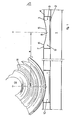
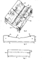
- Fig. 1 there is shown a concrete base floor 1 to which at certain regions flat layers 2 of mortar are applied.
- Floor elements 3 are laid on these layers 2.
- the base floor 1 is covered by a kerb 4 made of steel-fibre reinforced concrete which provides a track or surface suitable to carry the load of coil lifting transporters driving over it.
- Fig. 2 shows that the elements 3 are aligned and abutting end-to-end in longitudinal rows which present a continuous concavity for the coils. Two such elements 13,14 are shown in this figure.
- Each floor element 3 has a generally segmental cross-section smoothly curving concavity 5 whose defining chord lies in the same horizontal plane as the upper surface of the kerb region 4 on each side. At each side the segmental concavity passes gradually via a convex rounding 6 into the horizontal surface strip 7 of the element 3 which adjoins the upper surface of the kerb block. The lowest part of the concavity 5 has a groove 8 extending longitudinally in which loose dirt may collect.
- pegs 9 and peg-holes are used as coupling elements; the pegs 9 fit into matching peg-holes in the longitudinally adjacent element.
- Fig. 1 shows a second identical floor element 10, spaced laterally from the element 3, with a coil 11 having central hole 12 placed on it.
- the centre-to-centre distance between the two parallel concavities is designated a and is chosen so that the coils do not contact each other and that a transporter, by which the coils can be moved, such as a fork lift truck, can deposit a coil without damaging the coils in neighbouring rows.
- the elements 3 are made from a resiliently deformable plastics, such as low density polyethylene.
- the deformability must be chosen suitably in accordance with the load (pressure) applied by the coils.
- Fig. 3 shows the front view of a floor element.
- the radius of curvature r l of the segmental concavity corresponds to the largest radius of the coils to be stored.
- the radius of curvature r 2 avoids sharp edges at the convex transition from the segmental section to the flat section and is determined experimentally.
- the height h of the segment is 130 mm, the width b 700 mm, the length 1 500 mm, the radius r 1 850 mm, the radius r 2 100 mm, the depth of the concavity u 50 mm, the centre-to-centre spacing a between two consecutive concavities 1900 mm and the thickness of the mortar layer 2 is 20 mm.
Landscapes
- Engineering & Computer Science (AREA)
- Mechanical Engineering (AREA)
- Floor Finish (AREA)
- Storage Of Web-Like Or Filamentary Materials (AREA)
- Replacement Of Web Rolls (AREA)
- Unwinding Webs (AREA)
- Warehouses Or Storage Devices (AREA)
- Discharge Heating (AREA)
Priority Applications (1)
| Application Number | Priority Date | Filing Date | Title |
|---|---|---|---|
| AT87200200T ATE51376T1 (de) | 1986-02-17 | 1987-02-10 | Stuetzboden fuer die lagerung von blechrollen. |
Applications Claiming Priority (2)
| Application Number | Priority Date | Filing Date | Title |
|---|---|---|---|
| NL8600389A NL8600389A (nl) | 1986-02-17 | 1986-02-17 | Vloer voor de opslag van cilindrische voorwerpen zoals gewikkelde rollen. |
| NL8600389 | 1986-02-17 |
Publications (2)
| Publication Number | Publication Date |
|---|---|
| EP0234635A1 true EP0234635A1 (fr) | 1987-09-02 |
| EP0234635B1 EP0234635B1 (fr) | 1990-03-28 |
Family
ID=19847584
Family Applications (1)
| Application Number | Title | Priority Date | Filing Date |
|---|---|---|---|
| EP87200200A Expired - Lifetime EP0234635B1 (fr) | 1986-02-17 | 1987-02-10 | Plancher de support pour le stockage de bobines d'acier |
Country Status (6)
| Country | Link |
|---|---|
| EP (1) | EP0234635B1 (fr) |
| AT (1) | ATE51376T1 (fr) |
| DE (1) | DE3762030D1 (fr) |
| ES (1) | ES2014462B3 (fr) |
| GR (1) | GR3000414T3 (fr) |
| NL (1) | NL8600389A (fr) |
Citations (4)
| Publication number | Priority date | Publication date | Assignee | Title |
|---|---|---|---|---|
| US2588278A (en) * | 1948-06-23 | 1952-03-04 | Floyd B Noerr | Apparatus for transporting beams |
| CA1072919A (fr) * | 1976-10-25 | 1980-03-04 | Raymond K. Rogers | Palette berceau |
| US4195732A (en) * | 1978-02-28 | 1980-04-01 | Great Northern Corporation | Supporting and spacing member for web material rolls |
| EP0075975A1 (fr) * | 1981-09-24 | 1983-04-06 | Hoogovens Groep B.V. | Support pour objets cylindriques p.ex. des bandes métalliques enroulées |
-
1986
- 1986-02-17 NL NL8600389A patent/NL8600389A/nl not_active Application Discontinuation
-
1987
- 1987-02-10 EP EP87200200A patent/EP0234635B1/fr not_active Expired - Lifetime
- 1987-02-10 DE DE8787200200T patent/DE3762030D1/de not_active Expired - Lifetime
- 1987-02-10 ES ES87200200T patent/ES2014462B3/es not_active Expired - Lifetime
- 1987-02-10 AT AT87200200T patent/ATE51376T1/de active
-
1990
- 1990-03-29 GR GR90400133T patent/GR3000414T3/el unknown
Patent Citations (4)
| Publication number | Priority date | Publication date | Assignee | Title |
|---|---|---|---|---|
| US2588278A (en) * | 1948-06-23 | 1952-03-04 | Floyd B Noerr | Apparatus for transporting beams |
| CA1072919A (fr) * | 1976-10-25 | 1980-03-04 | Raymond K. Rogers | Palette berceau |
| US4195732A (en) * | 1978-02-28 | 1980-04-01 | Great Northern Corporation | Supporting and spacing member for web material rolls |
| EP0075975A1 (fr) * | 1981-09-24 | 1983-04-06 | Hoogovens Groep B.V. | Support pour objets cylindriques p.ex. des bandes métalliques enroulées |
Also Published As
| Publication number | Publication date |
|---|---|
| EP0234635B1 (fr) | 1990-03-28 |
| ATE51376T1 (de) | 1990-04-15 |
| NL8600389A (nl) | 1987-09-16 |
| DE3762030D1 (de) | 1990-05-03 |
| ES2014462B3 (es) | 1990-07-16 |
| GR3000414T3 (en) | 1991-06-28 |
Similar Documents
| Publication | Publication Date | Title |
|---|---|---|
| US5102286A (en) | Trailer and trailer unloading system | |
| US5809907A (en) | Pallet assembly | |
| US4013020A (en) | Flexure-compensating device for flexible pallets supporting very heavy loads | |
| US4597339A (en) | Pallet | |
| US20060179750A1 (en) | Composite beam | |
| US10836576B2 (en) | Storage decks and storage rack assemblies including same | |
| DE05812848T1 (de) | Doppelfolienpalette | |
| EP0291116B1 (fr) | Structure de support pour des semis | |
| EP0234635B1 (fr) | Plancher de support pour le stockage de bobines d'acier | |
| US20250042703A1 (en) | Nestable wheel ramps with removable chocks | |
| EP2930269B1 (fr) | Joint structurel | |
| CN112777084A (zh) | 货盘 | |
| EP0162406B1 (fr) | Traverses de voies ferrées | |
| EP3480086B1 (fr) | Tôle de fond et profilé de fond, en particulier en tant que surfaces d'appui pour véhicules à transporter | |
| US4832309A (en) | Moulding pallet | |
| EP2385173A1 (fr) | Système de pavage | |
| EP0302815A1 (fr) | Maillon à étai pour chaînes de pneu | |
| US2369733A (en) | Portable deck | |
| EP0344844B1 (fr) | Planche à fromage | |
| JPS6334034Y2 (fr) | ||
| AU643015B2 (en) | Traffic grating | |
| CN215154909U (zh) | 一种物料存储周转车 | |
| DE102019116971A1 (de) | Nutzfahrzeug-Ladebodenteil zum Bilden eines Ladebodens eines Nutzfahrzeugs | |
| JPH049317Y2 (fr) | ||
| DE9108561U1 (de) | Gepreßte Kunststoff-Palette |
Legal Events
| Date | Code | Title | Description |
|---|---|---|---|
| PUAI | Public reference made under article 153(3) epc to a published international application that has entered the european phase |
Free format text: ORIGINAL CODE: 0009012 |
|
| 17P | Request for examination filed |
Effective date: 19870210 |
|
| AK | Designated contracting states |
Kind code of ref document: A1 Designated state(s): AT BE CH DE ES FR GB GR IT LI LU NL SE |
|
| 17Q | First examination report despatched |
Effective date: 19881205 |
|
| GRAA | (expected) grant |
Free format text: ORIGINAL CODE: 0009210 |
|
| AK | Designated contracting states |
Kind code of ref document: B1 Designated state(s): AT BE CH DE ES FR GB GR IT LI LU NL SE |
|
| REF | Corresponds to: |
Ref document number: 51376 Country of ref document: AT Date of ref document: 19900415 Kind code of ref document: T |
|
| ITF | It: translation for a ep patent filed | ||
| ET | Fr: translation filed | ||
| REF | Corresponds to: |
Ref document number: 3762030 Country of ref document: DE Date of ref document: 19900503 |
|
| R20 | Corrections of a patent specification |
Effective date: 19900625 |
|
| REG | Reference to a national code |
Ref country code: GR Ref legal event code: FG4A Free format text: 3000414 |
|
| PLBE | No opposition filed within time limit |
Free format text: ORIGINAL CODE: 0009261 |
|
| STAA | Information on the status of an ep patent application or granted ep patent |
Free format text: STATUS: NO OPPOSITION FILED WITHIN TIME LIMIT |
|
| 26N | No opposition filed | ||
| ITTA | It: last paid annual fee | ||
| EPTA | Lu: last paid annual fee | ||
| EAL | Se: european patent in force in sweden |
Ref document number: 87200200.1 |
|
| PGFP | Annual fee paid to national office [announced via postgrant information from national office to epo] |
Ref country code: NL Payment date: 19971231 Year of fee payment: 12 |
|
| PGFP | Annual fee paid to national office [announced via postgrant information from national office to epo] |
Ref country code: FR Payment date: 19980112 Year of fee payment: 12 |
|
| PGFP | Annual fee paid to national office [announced via postgrant information from national office to epo] |
Ref country code: AT Payment date: 19980115 Year of fee payment: 12 |
|
| PGFP | Annual fee paid to national office [announced via postgrant information from national office to epo] |
Ref country code: SE Payment date: 19980116 Year of fee payment: 12 |
|
| PGFP | Annual fee paid to national office [announced via postgrant information from national office to epo] |
Ref country code: GB Payment date: 19980121 Year of fee payment: 12 |
|
| PGFP | Annual fee paid to national office [announced via postgrant information from national office to epo] |
Ref country code: DE Payment date: 19980126 Year of fee payment: 12 |
|
| PGFP | Annual fee paid to national office [announced via postgrant information from national office to epo] |
Ref country code: CH Payment date: 19980127 Year of fee payment: 12 |
|
| PGFP | Annual fee paid to national office [announced via postgrant information from national office to epo] |
Ref country code: GR Payment date: 19980130 Year of fee payment: 12 |
|
| PGFP | Annual fee paid to national office [announced via postgrant information from national office to epo] |
Ref country code: LU Payment date: 19980203 Year of fee payment: 12 |
|
| PGFP | Annual fee paid to national office [announced via postgrant information from national office to epo] |
Ref country code: BE Payment date: 19980205 Year of fee payment: 12 |
|
| PGFP | Annual fee paid to national office [announced via postgrant information from national office to epo] |
Ref country code: ES Payment date: 19980212 Year of fee payment: 12 |
|
| PG25 | Lapsed in a contracting state [announced via postgrant information from national office to epo] |
Ref country code: LU Free format text: LAPSE BECAUSE OF NON-PAYMENT OF DUE FEES Effective date: 19990210 Ref country code: GB Free format text: LAPSE BECAUSE OF NON-PAYMENT OF DUE FEES Effective date: 19990210 Ref country code: AT Free format text: LAPSE BECAUSE OF NON-PAYMENT OF DUE FEES Effective date: 19990210 |
|
| PG25 | Lapsed in a contracting state [announced via postgrant information from national office to epo] |
Ref country code: SE Free format text: LAPSE BECAUSE OF NON-PAYMENT OF DUE FEES Effective date: 19990211 Ref country code: ES Free format text: LAPSE BECAUSE OF NON-PAYMENT OF DUE FEES Effective date: 19990211 |
|
| PG25 | Lapsed in a contracting state [announced via postgrant information from national office to epo] |
Ref country code: LI Free format text: LAPSE BECAUSE OF NON-PAYMENT OF DUE FEES Effective date: 19990228 Ref country code: GR Free format text: LAPSE BECAUSE OF NON-PAYMENT OF DUE FEES Effective date: 19990228 Ref country code: CH Free format text: LAPSE BECAUSE OF NON-PAYMENT OF DUE FEES Effective date: 19990228 Ref country code: BE Free format text: LAPSE BECAUSE OF NON-PAYMENT OF DUE FEES Effective date: 19990228 |
|
| BERE | Be: lapsed |
Owner name: HOOGOVENS GROEP B.V. Effective date: 19990228 |
|
| PG25 | Lapsed in a contracting state [announced via postgrant information from national office to epo] |
Ref country code: NL Free format text: LAPSE BECAUSE OF NON-PAYMENT OF DUE FEES Effective date: 19990901 |
|
| GBPC | Gb: european patent ceased through non-payment of renewal fee |
Effective date: 19990210 |
|
| REG | Reference to a national code |
Ref country code: CH Ref legal event code: PL |
|
| PG25 | Lapsed in a contracting state [announced via postgrant information from national office to epo] |
Ref country code: FR Free format text: LAPSE BECAUSE OF NON-PAYMENT OF DUE FEES Effective date: 19991029 |
|
| EUG | Se: european patent has lapsed |
Ref document number: 87200200.1 |
|
| PG25 | Lapsed in a contracting state [announced via postgrant information from national office to epo] |
Ref country code: DE Free format text: LAPSE BECAUSE OF NON-PAYMENT OF DUE FEES Effective date: 19991201 |
|
| REG | Reference to a national code |
Ref country code: FR Ref legal event code: ST |
|
| REG | Reference to a national code |
Ref country code: ES Ref legal event code: FD2A Effective date: 20010910 |
|
| PG25 | Lapsed in a contracting state [announced via postgrant information from national office to epo] |
Ref country code: IT Free format text: LAPSE BECAUSE OF NON-PAYMENT OF DUE FEES;WARNING: LAPSES OF ITALIAN PATENTS WITH EFFECTIVE DATE BEFORE 2007 MAY HAVE OCCURRED AT ANY TIME BEFORE 2007. THE CORRECT EFFECTIVE DATE MAY BE DIFFERENT FROM THE ONE RECORDED. Effective date: 20050210 |