EP0234603B1 - X-ray generator with control of dosing power - Google Patents
X-ray generator with control of dosing power Download PDFInfo
- Publication number
- EP0234603B1 EP0234603B1 EP87200013A EP87200013A EP0234603B1 EP 0234603 B1 EP0234603 B1 EP 0234603B1 EP 87200013 A EP87200013 A EP 87200013A EP 87200013 A EP87200013 A EP 87200013A EP 0234603 B1 EP0234603 B1 EP 0234603B1
- Authority
- EP
- European Patent Office
- Prior art keywords
- value
- examination
- dose rate
- sampling
- controller
- Prior art date
- Legal status (The legal status is an assumption and is not a legal conclusion. Google has not performed a legal analysis and makes no representation as to the accuracy of the status listed.)
- Expired - Lifetime
Links
Images

Classifications
-
- H—ELECTRICITY
- H05—ELECTRIC TECHNIQUES NOT OTHERWISE PROVIDED FOR
- H05G—X-RAY TECHNIQUE
- H05G1/00—X-ray apparatus involving X-ray tubes; Circuits therefor
- H05G1/08—Electrical details
- H05G1/26—Measuring, controlling or protecting
- H05G1/30—Controlling
- H05G1/38—Exposure time
- H05G1/42—Exposure time using arrangements for switching when a predetermined dose of radiation has been applied, e.g. in which the switching instant is determined by measuring the electrical energy supplied to the tube
- H05G1/44—Exposure time using arrangements for switching when a predetermined dose of radiation has been applied, e.g. in which the switching instant is determined by measuring the electrical energy supplied to the tube in which the switching instant is determined by measuring the amount of radiation directly
-
- H—ELECTRICITY
- H05—ELECTRIC TECHNIQUES NOT OTHERWISE PROVIDED FOR
- H05G—X-RAY TECHNIQUE
- H05G1/00—X-ray apparatus involving X-ray tubes; Circuits therefor
- H05G1/08—Electrical details
- H05G1/26—Measuring, controlling or protecting
- H05G1/30—Controlling
- H05G1/36—Temperature of anode; Brightness of image power
-
- H—ELECTRICITY
- H05—ELECTRIC TECHNIQUES NOT OTHERWISE PROVIDED FOR
- H05G—X-RAY TECHNIQUE
- H05G1/00—X-ray apparatus involving X-ray tubes; Circuits therefor
- H05G1/08—Electrical details
- H05G1/26—Measuring, controlling or protecting
- H05G1/30—Controlling
- H05G1/46—Combined control of different quantities, e.g. exposure time as well as voltage or current
Definitions
- the invention relates to an X-ray generator with actuators at least for the tube current and the tube voltage, a controller which acts on the actuators as a function of the actual value and the target value of the dose rate, at least one measuring device for measuring the actual value of the dose rate, and with one by the user operable selection device which determines the type of examination and the target value of the dose rate.
- Such an X-ray generator is known from DE-OS 26 53 252. With this, on the one hand slice pictures can be taken and on the other hand bucky pictures in which the recording time does not exceed an upper and a lower limit value.
- the actuators for the tube current and the tube voltage have different time constants.
- different types of examination can have different actuating functions, i.e. a different assignment of the respective values of tube current and tube voltage.
- the controller is a sampling controller formed by a microprocessor system with an adjustable sampling frequency, that a memory is provided in which the sampling frequency and the actuating function are stored for the various types of examination, and that the sampling controller according to the actuating function and after calculates the manipulated variables for the next sampling interval in a program stored in a further memory and controls the actuators accordingly.
- the sampling frequency of the sampling controller and thus the control speed can be determined by means of a programmable counter contained in the microprocessor system, which is loaded from the memory with a value corresponding to the sampling interval and assigned to the respective type of examination.
- the implementation of these control functions and the control behavior (proportional behavior or integral behavior) of the dose rate control in the respective type of examination are determined by the program, according to which the manipulated variables for the next sampling interval are determined in the sampling controller.
- the dose rate in the different types of examination is not determined with the same measuring organ.
- the dose rate in a slice image can be determined, for example, with an ionization chamber, while it is determined in operation with a cinema camera by means of a photo multiplier and is derived from the video signal in fluoroscopic mode.
- a further development of the invention provides that several measuring devices are provided, one of which is effective for each type of examination, that matching amplifiers are provided which output the measuring device at a predetermined dose rate bring to a predetermined level, and that a switching device is provided which couples the measuring device intended for the respective examination with the sampling controller.
- the scanning frequency has a first value in a first section of an X-ray image and a second value in a subsequent section, and that the first value is significantly greater than the second value.
- a favorable transient response can be achieved if the first section is ended with a high sampling frequency as soon as, for example, the tube voltage has reached a predeterminable fraction of its starting value.
- simpler and shorter control algorithms must be used because of the increased sampling frequency, which ensure that an evaluable dose rate signal is available sufficiently quickly as long as the tube voltage does not yet deviate significantly from its starting value.
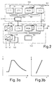
- Fig. I shows a schematic representation X-ray system with an X-ray generator I and an X-ray tube 2, the radiation of which passes through an examination area symbolized by the body 13 and generates an X-ray silhouette either on a film positioned in a cassette holder 4 or on the output screen of an X-ray image intensifier 5.
- the dose or the dose rate is measured by means of an ionization chamber 3 and fed to a unit 30 for dose evaluation.
- the output image of the image intensifier 5 can be recorded by means of a cinema camera 7, a sheet or roll film camera 8 or a television camera 9 or a television chain 90 with monitor 91 connected to it.
- An adjustable iris diaphragm 11 is located in the optical beam path.
- the X-ray generator I contains i.a. Actuators with which the tube voltage, the tube current and the focal spot size can be set.
- the tube voltage actuator 100 can contain, for example, a medium frequency converter with a high voltage generator and a rectifier combination.
- a grid control unit or an electronically controlled heating circuit can serve as the tube current actuator 110, and the focal spot actuator 120 can also be designed such that only the focal spot size can be switched between two values.
- the actuators 100, 110 and 120 receive their actuating signals via lines 143, 141 and 142 from a sampling controller 140. This receives its setpoints and actuating functions from a central control unit and its actual values either from the ionization chamber 3, the photomultiplier 12 or the television chain 90 Matching amplifiers 171, 172 and 173, which bring the output signals of these measuring operations to a normalized level and via the switching device 170, which is controlled via line 175 in such a way that the output signal of one of the three matching amplifiers 171. .173 is fed.
- the central control unit 160 is coupled via a bidirectional connection 162 to a selection device in the form of an operating panel 180.
- the user selects the type of examination, for example by pressing a key, whereupon the associated sampling frequency and the actuating function are called up in a memory of the central control unit 160 and loaded into a memory of the sampling controller 140 via the connection 159.
- sampling controller 140 and the central control unit 160 results from FIG. 2. Both contain a microprocessor 147 and 165 as well as read-only and read / write memories 148 and 166 and input / output units 149 and 164, 167. Both units contain one Programmable counters 150 and 169, respectively.
- the sampling controller 140 also contains an analog-to-digital converter 146 for converting the analog signals representing the actual values on line 144 into digital values and digital-to-analog converters 145 which produce the digital actuating signals generated by the microprocessor 147 convert into analog signals, which reach the associated actuators via lines 141, 142 and 143.
- the optimal actuating function, the required sampling frequency and further parameters e.g. the frame rate, the minimum and the maximum recording time (with cinema recording technology) etc. are saved.
- These programs can be called up from the control panel 180 via the bidirectional connection 162.
- They are transmitted via the input / output interface 167 of the central control unit 160 and the connection 159 to the input / output interface 149 of the sampling controller 140.
- the recording time is set by means of the programmable counter 169, which is started by the recording start signal and generates a signal when the recording expires, which is transmitted via the u.a.
- Line 161 connected to high-voltage actuator 100 switches off the tube voltage and thus the X-ray radiation, and this acts on microprocessor 147 in sampling controller 140 via interrupt line 158.
- the latter calculates the actuating signals for the next sampling interval within a sampling interval.
- x-ray images are generated with the cinema camera, generally between 50 and 300 images per second, x-ray images being generated. It is necessary to regulate the dose per image. Dose deviations occurring due to disturbance variables do not have to be corrected within a picture, but after a few ten pictures, since otherwise a restless picture impression (flickering) would result. The dose is therefore a scanning signal that is available after each image. The sampling frequency thus corresponds to the frame rate.
- U i is the tube voltage set during the last image and a is the exponent with which the dose rate changes when the tube voltage changes.
- the voltage U x calculated in this way represents the value that would be required in the case of a control with proportional behavior, in which the dose or the dose rate is regulated exclusively by changing the tube voltage.
- the tube current I x associated with U x is then determined as a function of the actuating function loaded for this type of examination.
- An actuating function suitable for cinema operation is shown in FIG. 3a.
- the curve entered in the tube current / tube voltage diagram indicates the manner in which tube voltage and tube current are to be changed in order to achieve a change in the dose rate.
- the curve begins with the smallest possible tube voltage and the smallest possible tube current with a horizontal section, ie only the voltage is changed in this area to change the dose rate.
- This section is followed by a second section in which tube current and tube voltage are changed in the same direction in order to change the dose rate.
- This second section is followed by a third, again horizontally running section, which is determined by the maximum tube current.
- This third section is followed by a fourth section, which is predetermined by the resilience of the focal spot of the X-ray tube and which has a hyperbolic shape.
- tube voltage and tube current are changed in opposite directions to one another so that their product remains constant.
- the actuating function shown in Fig. 3a is stored in that the values of tube current and tube voltage are stored at the start and end points of the individual sections.
- the description of the characteristic curve using the start and end points may not be sufficient. In this case, a large number of points are stored on the characteristic curve.
- a tube current change AI x is determined according to the formula calculated.
- h is a factor that determines the proportional behavior of the control, while the factor k defines the integral behavior of the control.
- the value l il is the tube current during the penultimate picture.
- the regulation in the case of pulsed fluoroscopy in which the actual value is derived from the signals of the television chain 90, can be carried out in a similar manner. However, a different sampling frequency and a different actuating function can be specified.
- each image should be correctly exposed, whereby the recording time should not exceed a lower and an upper limit frequency.
- the imaging dose rate In order not to exceed the limit of the exposure time for no single exposure, the imaging dose rate must be regulated.
- An adapted sampling frequency results from the shortest recording time. If it is 10 to 20 ms, the sampling frequency should be around I kHz.
- the end of admission takes place when the target dose required for admission has been reached.
- the sampling frequency is at a value at the start of an image in the period from switching on until approximately 95% of the starting value of the tube voltage has been reached is set, which is much higher, e.g. 5 kHz.
- simpler and shorter control algorithms must be used, which differ from the above-mentioned ones in that on the one hand it should be detected whether there is an evaluable dose rate and on the other hand a sufficiently rapid tube voltage change should occur if the measured dose rate is significantly too high. This prevents overexposure of the X-ray image.
- the sampling frequency is set to the above-mentioned value (I kHz).
Description
Die Erfindung betrifft einen Röntgengenerator mit Stellgliedern zumindest für den Röhrenstrom und die Röhrenspannung, einem Regler, der in Abhängigkeit von dem Istwert und dem Sollwert der Dosisleistung auf die Stellglieder einwirkt, wenigstens einer Meßeinrichtung zur Messung des Istwertes der Dosisleistung, und mit einer durch den Benutzer betätigbaren, die Untersuchungsart sowie den Sollwert der Dosisleistung festlegenden Wähleinrichtung.The invention relates to an X-ray generator with actuators at least for the tube current and the tube voltage, a controller which acts on the actuators as a function of the actual value and the target value of the dose rate, at least one measuring device for measuring the actual value of the dose rate, and with one by the user operable selection device which determines the type of examination and the target value of the dose rate.
Ein solcher Röntgengenerator ist aus der DE-OS 26 53 252 bekannt. Damit können einerseits Schichtaufnahmen angefertigt werden und andererseits Buckyaufnahmen, bei denen die Aufnahmezeit einen oberen und einen unteren Grenzwert nicht überschreitet. Die Stellglieder für den Röhrenstrom und die Röhrenspannung weisen unterschiedliche Zeitkonstanten auf.Such an X-ray generator is known from DE-OS 26 53 252. With this, on the one hand slice pictures can be taken and on the other hand bucky pictures in which the recording time does not exceed an upper and a lower limit value. The actuators for the tube current and the tube voltage have different time constants.
Viele Untersuchungsarten erfordern unterschiedliche Zeitkonstanten. Im Kinobetrieb und im gepulsten Durchleuchtungsbetrieb beispielsweise sind relativ große Zeitkonstanten erforderlich, um einen unruhigen Bildeindruck zu vermeiden. Bei Serienaufnahmebetrieb mit bis zu 15 Bildern pro Sekunde hingegen ist eine wesentlich schnellere Dosisleistungsregelung erforderlich.Many types of examination require different time constants. In cinema mode and in pulsed fluoroscopy mode, for example, relatively large time constants are required in order to avoid an uneasy picture impression. In contrast, in series recording mode with up to 15 frames per second, a much faster dose rate control is required.
Weiterhin können unterschiedliche Untersuchungsarten unterschiedliche Stellfunktionen, d.h. eine unterschiedliche Zuordnung der jeweiligen Werte von Röhrenstrom und Röhrenspannung, erfordern. Man müßte also für jede Untersuchungsart einen gesonderten Regler vorsehen, wenn man mit dem bekannten Röntgengenerator eine Dosisleistungsregelung bei den verschiedenen Untersuchungsarten erreichen wollte.Furthermore, different types of examination can have different actuating functions, i.e. a different assignment of the respective values of tube current and tube voltage. One would have to provide a separate controller for each type of examination if one wanted to achieve dose rate control for the various types of examination using the known X-ray generator.
Es ist Aufgabe der Erfindung, einen Röntgengenerator der engangs genannten Art so auszugestalten, daß mit geringem Aufwand eine für verschiedene Untersuchungsarten geeignete Dosisleistungsregelung erreicht wird.It is an object of the invention to design an X-ray generator of the type mentioned in such a way that a dose rate control suitable for different types of examination is achieved with little effort.
Diese Aufgabe wird dadurch gelöst, daß der Regler ein durch ein Mikroprozessorsystem gebildeter Abtastregler mit einstellbarer Abtastfrequenz ist, daß ein Speicher vorgesehen ist, in dem für die verschiedenen Untersuchungsarten jeweils die Abtastfrequenz und die Stellfunktion abgelegt sind, und daß der Abtastregler entsprechend der Stellfunktion und nach einem in einem weiteren Speicher abgelegten Programm die Stellgrößen für das nächste Abtastintervall berechnet und die Stellglieder entprechend steuert.This object is achieved in that the controller is a sampling controller formed by a microprocessor system with an adjustable sampling frequency, that a memory is provided in which the sampling frequency and the actuating function are stored for the various types of examination, and that the sampling controller according to the actuating function and after calculates the manipulated variables for the next sampling interval in a program stored in a further memory and controls the actuators accordingly.
Die Abtastfrequenz des Abtastreglers und damit die Regelgeschwindigkeit können mittels eines in dem Mikroprozessorsystem enthaltenen programmierbaren Zählers bestimmt werden, der mit einem dem Abtastintervall entsprechenden und der jeweiligen Untersuchungsart zugeordneten Wert aus dem Speicher geladen wird. Das gleiche gilt für die Stellfunktionen. Die Realisierung dieser Stellfunktionen und das Regelverhalten (Proportionalverhalten bzw. Integralverhalten) der Dosisleistungsregelung bei der jeweiligen Untersuchungsart werden durch das Programm bestimmt, nach dem in dem Abtastregler die Stellgrößen für das nächste Abtastintervall bestimmt werden.The sampling frequency of the sampling controller and thus the control speed can be determined by means of a programmable counter contained in the microprocessor system, which is loaded from the memory with a value corresponding to the sampling interval and assigned to the respective type of examination. The same applies to the control functions. The implementation of these control functions and the control behavior (proportional behavior or integral behavior) of the dose rate control in the respective type of examination are determined by the program, according to which the manipulated variables for the next sampling interval are determined in the sampling controller.
In der Regel wird die Dosisleistung in den verschiedenen Untersuchungsarten nicht mit demselben Meßorgan bestimmt. Die Dosisleistung bei einer Schichtaufnahme kann beispielsweise mit einer lonisationskammer bestimmt werden, während sie bei Betrieb mit einer Kinokamera mittels eines Fotovervielfachers bestimmt und im Durchleuchtungsbetrieb aus dem Videosignal abgeleitet wird. Um die Dosisleistungsregelung unabhängig vom konkreten Aufbau der jeweils benutzten Meßeinrichtung zu gewährleisten, sieht eine Weiterbildung der Erfindung vor, daß mehrere Meßeinrichtungen vorgesehen sind, von denen bei jeder Untersuchungsart jeweils eine wirksam ist, daß Anpaßverstärker vorgesehen sind, die das Ausgangssignal der Meßeinrichtung bei vorgegebener Dosisleistung auf einen vorgegebenen Pegel bringen, und daß eine Umschaltvorrichtung vorgesehen ist, die die für die jeweilige Untersuchung bestimmte Meßeinrichtung mit dem Abtastregler koppelt.As a rule, the dose rate in the different types of examination is not determined with the same measuring organ. The dose rate in a slice image can be determined, for example, with an ionization chamber, while it is determined in operation with a cinema camera by means of a photo multiplier and is derived from the video signal in fluoroscopic mode. In order to ensure the dose rate control independently of the specific structure of the measuring device used in each case, a further development of the invention provides that several measuring devices are provided, one of which is effective for each type of examination, that matching amplifiers are provided which output the measuring device at a predetermined dose rate bring to a predetermined level, and that a switching device is provided which couples the measuring device intended for the respective examination with the sampling controller.
Eine andere Weiterbildung der Erfindung sieht vor, daß die Abtastfrequenz in einem ersten Abschnitt einer Röntgenaufnahme einen ersten Wert und in einem darauffolgenden Abschnitt einen zweiten Wert hat, und daß der erste Wert wesentlich größer ist als der zweite Wert. Dadurch kann ein günstiges Einschwingverhalten erreicht werden, wenn der erste Abschnitt mit hoher Abtastfrequenz beendet wird, sobald beispielsweise die Röhrenspannung einen vorgebbaren Bruchteil ihres Startwertes erreicht hat. In der ersten Phase müssen wegen der erhöhten Abtastfrequenz einfachere und verkürzte Regelalgorithmen verwendet werden, die sicherstellen, daß hinreichend schnell schon ein auswertbares Dosisleistungssignal vorliegt, solange die Röhrenspannung noch nicht wesentlich von ihrem Startwert abweicht.Another development of the invention provides that the scanning frequency has a first value in a first section of an X-ray image and a second value in a subsequent section, and that the first value is significantly greater than the second value. As a result, a favorable transient response can be achieved if the first section is ended with a high sampling frequency as soon as, for example, the tube voltage has reached a predeterminable fraction of its starting value. In the first phase, simpler and shorter control algorithms must be used because of the increased sampling frequency, which ensure that an evaluable dose rate signal is available sufficiently quickly as long as the tube voltage does not yet deviate significantly from its starting value.
Die Erfindung wird nachstehend anhand der Zeichnung näher erläutert. Es zeigen:
- Fig. I ein Blockschaltbild eines Röntgengenerators nach der Erfindung,
- Fig. 2 ein Blockschaltbild eines Teils des Röntgengenerators und
- Fig. 3a und 3b Stellfunktionen für verschiedene Untersuchungsarten.
- I is a block diagram of an X-ray generator according to the invention,
- Fig. 2 is a block diagram of part of the X-ray generator and
- 3a and 3b actuating functions for different types of examination.
Fig. I zeigt in schematischer Darstellung eine Röntgenanlage mit einem Röntgengenerator I und einer Röntgenröhre 2, deren Strahlung einen durch den Körper 13 symbolisierten Untersuchungsbereich durchsetzt und entweder auf einem in einem Kassettenhalter 4 positionierten Film oder am Ausgangsschirm eines Röntgenbildverstärkers 5 ein Röntgenschattenbild erzeugt. Bei Verwendung eines Röntgenfilms wird die Dosis bzw. die Dosisleistung mittels einer lonisationskammer 3 gemessen und einer Einheit 30 zur Dosisauswertung zugeführt. Das Ausgangsbild des Bildverstärkers 5 kann mittels einer Kinokamera 7, einer Blatt- oder Rollfilmkamera 8 oder einer Fernsehkamera 9 bzw einer daran angeschlossenen Fernsehkette 90 mit Monitor 91 aufgenommen werden. Im optischen Strahlengang befindet sich eine einstellbare Irisblende 11.Fig. I shows a schematic representation X-ray system with an X-ray generator I and an
Der Röntgengenerator I enthält u.a. Stellglieder, mit denen die Röhrenspannung, der Röhrenstrom und die Brennfleckgröße eingestellt werden können. Das Röhrenspannungs-Stellglied 100 kann beispielsweise einen Mittelfrequenzumrichter mit Hochspannungserzeuger und Gleichrichterkombination enthalten. Als Röhrenstrom-Stellglied 110 kann eine Gittersteuerungseinheit dienen oder ein elektronisch geregelter Heizkreis, und das Brennfleck-Stellglied 120 kann auch so ausgebildet sein, daß damit nur die Brennfleckgröße zwischen zwei Werten umgeschaltet werden kann.The X-ray generator I contains i.a. Actuators with which the tube voltage, the tube current and the focal spot size can be set. The
Die Stellglieder 100, 110 bzw. 120 erhalten ihre Stellsignale über Leitungen 143, 141 bzw. 142 von einem Abtastregler 140. Dieser erhält seine Sollwerte und Stellfunktionen aus einer Zentralsteuereinheit und seine Istwerte entweder von der lonisationskammer 3, dem Fotovervielfacher 12 oder der Fernsehkette 90 über Anpaßverstärker 171, 172 und 173, die die Ausgangssignale dieser Meßorgange auf einen normierten Pegel bringen und über die Umschaltvorrichtung 170, die über die Leitung 175 so gesteuert wird, daß dem Abtastregler 140 über die Leitung 144 das Ausgangssignal jeweils eines der drei Anpaßverstärker 171...173 zugeführt wird.The
Die Zentralsteuereinheit 160 ist über eine bidirektionale Verbindung 162 mit einer Wähleinrichtung in Form eines Bedienpultes 180 gekoppelt. Der Benutzer wählt hierbei beispielsweise durch Betätigen einer Taste die Untersuchungsart, woraufhin in einem Speicher der Zentralsteuereinheit 160 die zugehörige Abtastfrequenz sowie die Stellfunktion aufgerufen und über die Verbindung 159 in einen Speicher des Abtastreglers 140 geladen werden.The
Der Aufbau des Abtastreglers 140 und der Zentralsteuereinheit 160 ergibt sich aus Fig. 2. Beide enthalten einen Mikroprozessor 147 bzw. 165 sowie Festwert- und Schreib/Lesespeicher 148 bzw. 166 und Ein/Ausgabeeinheiten 149 bzw. 164, 167. Beide Einheiten enthalten einen programmierbaren Zähler 150 bzw. 169. Der Abtastregler 140 enthält darüber hinaus einen Analog-Digital-Wandler 146 zur Umsetzung der die Istwerte darstellenden analogen Signale auf der Leitung 144 in Digitalwerte und Digital-Analog-Wandler 145, die die vom Mikroprozessor 147 erzeugten digitalen Stellsignale in Analogsignale umsetzen, welche über die Leitungen 141, 142 und 143 zu den zugehörigen Stellgliedern gelangen.The structure of the
In dem Speicher 166 der Zentralsteuereinheit 160 sind für jede Untersuchungsart die optimale Stellfunktion, die erforderliche Abtastfrequenz sowie weitere Parameter, z.B. die Bildfrequenz, die minimale und die maximale Aufnahmezeit (bei Kinoaufnahmetechnik) usw. gespeichert. Diese Programme können über die bidirektionale Verbindung 162 vom Bedienpult 180 aus aufgerufen werden. Sie werden vor Beginn der Aufnahme über die Ein/Ausgabe-Schnittstelle 167 der Zentralsteuereinheit 160 und die Verbindung 159 an die Ein/Ausgabe-Schnittstelle 149 des Abtastreglers 140 übertragen. Die Stellung der Aufnahmezeit erfolgt mittels des programmierbaren Zählers 169, der vom Aufnahmebeginnsignal gestartet wird und bei Ablauf der Aufnahme ein Signal erzeugt, das über die u.a. mit dem Hochspannungs-Stellglied 100 verbundene Leitung 161 die Röhrenspannung und damit die Röntgenstrahlung abschaltet, und das über die Interruptleitung 158 auf den Mikroprozessor 147 im Abtastregler 140 einwirkt. Dieser berechnet nach einem in dem Speicher 148 abgelegten Programm, das in Abhängigkeit von der jeweiligen Untersuchungsart aufgerufen wird, innerhalb eines Abtastintervalls die Stellsignale für das nächste Abtastintervall.In the
Die Funktion des Röntgengenerators soll nachstehend für zwei verschiedene Untersuchungsarten erläutert werden.The function of the X-ray generator will be explained below for two different types of examination.
Bei dieser Untersuchungsart wird mit der Kinokamera eine Vielzahl von Röntgenbilder erzeugt, im allgemeinen zwischen 50 und 300 Bildern pro Sekunde, Röntgenbilder erzeugt. Dabei ist an sich eine Regelung der Dosis pro Bild erforderlich. Aufgrund von Störgrößen auftretende Dosisabweichungen müssen jedoch nicht innerhalb eines Bildes, sondern nach einigen zehn Bildern ausgeregelt werden, da anderenfalls ein unruhiger Bildeindruck (Flackern) entstünde. Die Dosis ist damit ein Abtastsignal, das nach jedem Bild zur Verfügung steht. Die Abtastfrequenz entspricht also dabei der Bildfrequenz.In this type of examination, a large number of x-ray images are generated with the cinema camera, generally between 50 and 300 images per second, x-ray images being generated. It is necessary to regulate the dose per image. Dose deviations occurring due to disturbance variables do not have to be corrected within a picture, but after a few ten pictures, since otherwise a restless picture impression (flickering) would result. The dose is therefore a scanning signal that is available after each image. The sampling frequency thus corresponds to the frame rate.
Es sei angenommen, daß nach dem i-ten Bild einer Folge von Kinobildern ein Signal D; anliege, das die während dieses Bildes empfangene Dosis darstellen soll. Die für die richtige Schwärzung eines Bildes erforderliche Dosis möge jedoch Ds sein und von D; abweichen. Die erforderlichen Stellsignale für das Röhrenspannungs-Stellglied 100 und dasRöhrenstrom-Stellglied 110 werden dann wie folgt berechnet:It is assumed that after the i-th picture of a sequence of cinema pictures a signal D ; to represent the dose received during this image. However, the dose required to properly darken an image may be D s and D ; differ. The Required control signals for the
A.I) Es wird zunächst eine Röhrenspannung Ux nach der Beziehung![]()
![]()
Dabei ist Ui die während des letzten Bildes eingestellte Röhrenspannung und a der Exponent, mit dem sich die Dosisleistung bei einer Änderung der Röhrenspannung ändert. Die so berechnete Spannung Ux stellt den Wert dar, der bei einer Regelung mit Proportionalverhalten erforderlich wäre, bei der die Dosis bzw. die Dosisleistung ausschließlich durch Änderung der Röhrenspannung geregelt wird.U i is the tube voltage set during the last image and a is the exponent with which the dose rate changes when the tube voltage changes. The voltage U x calculated in this way represents the value that would be required in the case of a control with proportional behavior, in which the dose or the dose rate is regulated exclusively by changing the tube voltage.
Anschließend wird in Abhängigkeit von der für diese Untersuchungsart geladenen Stellfunktion der zu Ux zugehörende Röhrenstrom Ix bestimmt. Eine für den Kinobetrieb geeignete Stellfunktion ist in Fig. 3a dargestellt. Die in dem Röhrenstrom/Röhrenspannungsdiagramm eingetragene Kurve gibt an, in welcher Weise Röhrenspannung und Röhrenstrom geändert werden sollen, um eine Änderung der Dosisleistung zu erreichen. Die Kurve beginnt bei der kleinstmöglichen Röhrenspannung und dem kleinstmöglichen Röhrenstrom mit einem horizontalen Abschnitt, d.h. zur Änderung der Dosisleistung wird in diesem Bereich lediglich die Spannung geändert. An diesen Abschnitt schließt sich ein zweiter Abschnitt an, in dem zur Änderung der Dosisleistung Röhrenstrom und Röhrenspannung gleichsinnig geändert werden. Diesem zweiten Abschnitt folgt ein dritter, wiederum horizontal verlaufender Abschnitt, der durch den maximalen Röhrenstrom bestimmt ist. Auf diesen dritten Abschnitt folgt ein vierter Abschnitt, der durch die Belastbarkeit des Brennflecks der Röntgenröhre vorgegeben ist und der einen hyperbelförmigen Verlauf hat. In diesem Abschnitt werden zur Änderung einer Dosisleistung Röhrenspannung und Röhrenstrom gegensinnig zueinander so verändert, daß ihr Produkt konstant bleibt. Die in Fig. 3a dargestellte Stellfunktion wird dadurch gespeichert, daß die Werte von Röhrenstrom und Röhrenspannung an den Anfangs- bzw. Endpunkten der einzelnen Abschnitte gespeichert werden. Für Zwischenstellgrößen (z.B. Heizstrom), die nichtlineare Abhängigkeiten zu Röhrenstrom und Röhrenspannung aufweisen, kann die Beschreibung der Kennlinie mittels der Anfangs- und Endpunkte nicht ausreichend sein. In diesem Fall werden eine Vielzahl von Punkten auf der Kennlinie gespeichert. A.3) Nachdem auf diese Weise anhand der Stellfunktion gemäß Fig. 3a der zu der Röhrenspannung Ux gehörendeRöhrenstrom Ix bestimmt ist, wird eine Röhrenstromänderung A Ix nach der Formel![]()
![]()
![]()
![]()
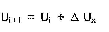
A.5) Die bei dem nächsten Röntgenbild einzustellende Röhrenspannung Ui+l wird nach der Beziehung![]()
![]()
In ähnliche Weise kann die Regelung bei der gepulsten Durchleuchtung erfolgen, bei der der Istwert aus den Signalen der Fernsehkette 90 abgeleitet wird. Allerdings können dabei eine andere Abtastfrequenz und eine andere Stellfunktion vorgegeben sein.The regulation in the case of pulsed fluoroscopy, in which the actual value is derived from the signals of the
Bei dieser Untersuchungsart mit Bildfrequenzen bis zu 15 Bildern pro Sekunde sollte jedes Bild korrekt belichtet sein, wobei die Aufnahmedauer einen unteren und einen oberen Grenzfrequenz nicht überschreiten soll. Um die Grenze der Aufnahmedauer bei keiner Einzelaufnahme zu überschreiten, muß die bildgebende Dosisleistung geregelt werden. Eine angepaßte Abtastfrequenz ergibt sich aus der kürzesten Aufnahmezeit. Wenn diese 10 bis 20 ms beträgt, sollte die Abtastfrequenz etwa I kHz betragen.In this type of examination with image frequencies of up to 15 frames per second, each image should be correctly exposed, whereby the recording time should not exceed a lower and an upper limit frequency. In order not to exceed the limit of the exposure time for no single exposure, the imaging dose rate must be regulated. An adapted sampling frequency results from the shortest recording time. If it is 10 to 20 ms, the sampling frequency should be around I kHz.
Zu diesem Zweck wird ein interner Teiler der Taktfrequenz des Abtastreglers entsprechend eingestellt und auf einen Interrupteingang der Zentraleinheit geschaltet, sobald die Röhrenspannung ihren zu Beginn vorgegebenen Startwert erreicht hat. In jedem dadurch angestoßenen Abtastintervall wird die Dosisleistung bzw. die bis dahin aufgelaufene Dosis über den Analog-Digital-Wandler 146 als Istwert eingelesen und die Differenz zu dem Führungswert aus dem Speicher wird bestimmt. Die Berechnung der Stellgröße erfolgt dabei wie folgt:
- B.I) Es wird zunächst eine Spannung Ux nach der Beziehung

- B.2) Im zweiten Schritt wird mit Hilfe des so berechneten Wertes Ux ein Wert A Ux gemäß der Formel

- B.4) In einem weiteren Schritt wird der zugehörige Röhrenstrom li,1 anhand der Stellfunktion ermittelt, die in diesem Fall gemäß Gleichung B.3) durch eine Gerade definiert wird, deren Eckpunkte gespeichert sind.
- BI) First there is a voltage U x according to the relationship
- B.2) In the second step, the value U x calculated in this way becomes a value AU x according to the formula
- B.4) In a further step, the associated tube current l i , 1 is determined on the basis of the actuating function, which in this case is defined according to equation B.3) by a straight line whose corner points are stored.
Das Aufnahmeende erfolgt, wenn die für die Aufnahme erforderliche Solldosis erreicht ist.The end of admission takes place when the target dose required for admission has been reached.
In ähnlicher Weise erfolgt die Regelung bei Schichtaufnahmen. Da bei diesen die Aufnahmezeit jedoch fest vorgegeben ist, erfolgt das Aufnahmeende in diesem Fall mit Hilfe eines programmierbaren Zählers.The control of slice images is carried out in a similar way. However, since the recording time is fixed in these cases, the end of the recording is done in this case with the aid of a programmable counter.
Bei den zuvor beschriebenen Untersuchungsarten, bei denen schon die einzelne Aufnahme richtig belichtet sein muß, ergibt sich ein besonders günstiges Einschwingverhalten, wenn zu Beginn einer Aufnahme im Zeitraum vom Einschalten bis zum Erreichen von ca. 95% des Startwertes der Röhrenspannung die Abtastfrequenz auf einen Wert gesetzt wird, der wesentlich höher ist, z.B. 5 kHz. Bei dieser erhöhten Abtastfrequenz müssen einfachere und verkürzte Regelalgorithmen verwendet werden, die sich von den oben genannten insofern unterscheiden, als einerseits detektiert werden soll, ob ein auswertbares Dosisleistung vorliegt und andererseits eine genügend schnelle Röhrenspannungsänderung erfolgen soll, wenn die gemessene Dosisleistung wesentlich zu hoch ist. Dadurch wird eine Überbelichtung des Röntgenbildes verhindert. Nach Ablauf des Einschwingvorganges wird die Abtastfrequenz auf den oben genannten Wert (I kHz) eingestellt.In the types of examination described above, in which the individual image must already be correctly exposed, there is a particularly favorable transient response if the sampling frequency is at a value at the start of an image in the period from switching on until approximately 95% of the starting value of the tube voltage has been reached is set, which is much higher, e.g. 5 kHz. With this increased sampling frequency, simpler and shorter control algorithms must be used, which differ from the above-mentioned ones in that on the one hand it should be detected whether there is an evaluable dose rate and on the other hand a sufficiently rapid tube voltage change should occur if the measured dose rate is significantly too high. This prevents overexposure of the X-ray image. After the settling process, the sampling frequency is set to the above-mentioned value (I kHz).
Claims (3)
Applications Claiming Priority (2)
| Application Number | Priority Date | Filing Date | Title |
|---|---|---|---|
| DE3600464 | 1986-01-10 | ||
| DE19863600464 DE3600464A1 (en) | 1986-01-10 | 1986-01-10 | X-RAY GENERATOR WITH DOSAGE PERFORMANCE CONTROL |
Publications (3)
| Publication Number | Publication Date |
|---|---|
| EP0234603A2 EP0234603A2 (en) | 1987-09-02 |
| EP0234603A3 EP0234603A3 (en) | 1988-08-17 |
| EP0234603B1 true EP0234603B1 (en) | 1992-07-08 |
Family
ID=6291589
Family Applications (1)
| Application Number | Title | Priority Date | Filing Date |
|---|---|---|---|
| EP87200013A Expired - Lifetime EP0234603B1 (en) | 1986-01-10 | 1987-01-07 | X-ray generator with control of dosing power |
Country Status (4)
| Country | Link |
|---|---|
| US (1) | US4797905A (en) |
| EP (1) | EP0234603B1 (en) |
| JP (1) | JP2591739B2 (en) |
| DE (2) | DE3600464A1 (en) |
Cited By (3)
| Publication number | Priority date | Publication date | Assignee | Title |
|---|---|---|---|---|
| US6553095B2 (en) | 1999-10-08 | 2003-04-22 | Dentsply Research & Development Corp | Automatic exposure control for dental panoramic and cephalographic x-ray equipment |
| US6775351B2 (en) | 2000-02-02 | 2004-08-10 | Gerardo Rinaldi | Automatic X-ray detection for intra-oral dental x-ray imaging apparatus |
| US7672425B2 (en) | 2002-07-25 | 2010-03-02 | Gendex Corp. | Real-time digital X-ray imaging apparatus |
Families Citing this family (22)
| Publication number | Priority date | Publication date | Assignee | Title |
|---|---|---|---|---|
| DE3732634A1 (en) * | 1987-09-28 | 1989-04-06 | Siemens Ag | X-RAY DIAGNOSTIC DEVICE |
| DE3801027A1 (en) * | 1988-01-15 | 1989-07-27 | Saunalux Gmbh Products & Co Kg | METHOD AND DEVICE FOR LARGE-SCALE RADIATION OF THE HUMAN BODY |
| US4980905A (en) * | 1989-02-16 | 1990-12-25 | General Electric Company | X-ray imaging apparatus dose calibration method |
| US5012504A (en) * | 1989-12-26 | 1991-04-30 | General Electric Company | Automatic brightness compensation for fluorography systems |
| US5003572A (en) * | 1990-04-06 | 1991-03-26 | General Electric Company | Automatic brightness compensation for x-ray imaging systems |
| DE4013703C2 (en) * | 1990-04-28 | 1999-04-01 | Bork Klaus Peter | Circuit arrangement for X-ray generators used in particular for diagnostic purposes |
| DE4235010A1 (en) * | 1992-10-16 | 1994-04-21 | Siemens Ag | X-ray diagnostic equipment with television chain - has maximum radiation reduction mode and maximum image quality mode selectable by control devices |
| JP2634369B2 (en) * | 1993-07-15 | 1997-07-23 | 浜松ホトニクス株式会社 | X-ray equipment |
| DE69913311T2 (en) * | 1998-10-19 | 2004-10-14 | Koninklijke Philips Electronics N.V. | X-RAY EXAMINATION DEVICE WITH REGULATION OF THE RADIATION DOSE |
| JP4549462B2 (en) * | 1999-10-14 | 2010-09-22 | ジーイー・メディカル・システムズ・エス アー | Method for improving image quality of fluoroscopic image and system for improving image quality of fluoroscopic image |
| US6795528B2 (en) * | 2001-01-12 | 2004-09-21 | Canon Kabushiki Kaisha | Radiographic apparatus, radiographic method, and computer-readable storage medium |
| US6810109B2 (en) * | 2001-07-13 | 2004-10-26 | Medtronic Ave, Inc. | X-ray emitting system and method |
| EP1408835A2 (en) * | 2001-07-25 | 2004-04-21 | Dentsply International, Inc. | Real-time digital x-ray imaging apparatus |
| JP2003142294A (en) * | 2001-10-31 | 2003-05-16 | Ge Medical Systems Global Technology Co Llc | High voltage generating circuit and x-ray generating device |
| DE10163583A1 (en) * | 2001-12-21 | 2003-07-03 | Philips Intellectual Property | Method and device for exposing x-rays |
| WO2003086028A1 (en) * | 2002-04-05 | 2003-10-16 | Hamamatsu Photonics K.K. | X-ray tube control apparatus and x-ray tube control method |
| US7431500B2 (en) * | 2003-04-01 | 2008-10-07 | Analogic Corporation | Dynamic exposure control in radiography |
| DE102004017180B4 (en) * | 2004-04-07 | 2007-08-02 | Siemens Ag | X-ray diagnostic device for digital radiography |
| US7274771B2 (en) * | 2005-05-03 | 2007-09-25 | General Electric Company | Methods and systems for controlling exposure for medical imaging devices |
| JP5785156B2 (en) * | 2009-05-05 | 2015-09-24 | コーニンクレッカ フィリップス エヌ ヴェ | Method and apparatus for load dependent resizing of a focal spot in an X-ray generator |
| US9168010B2 (en) * | 2012-04-11 | 2015-10-27 | Kabushiki Kaisha Toshiba | X-ray imaging apparatus and medical image processing apparatus |
| JP6009799B2 (en) * | 2012-04-11 | 2016-10-19 | 東芝メディカルシステムズ株式会社 | X-ray imaging device |
Family Cites Families (11)
| Publication number | Priority date | Publication date | Assignee | Title |
|---|---|---|---|---|
| US3675020A (en) * | 1969-09-24 | 1972-07-04 | Cgr Medical Corp | X-ray tube control circuitry |
| US3783286A (en) * | 1970-12-23 | 1974-01-01 | Picker Corp | X-ray image brightness stabilizer |
| DE2207280A1 (en) * | 1972-02-16 | 1973-08-23 | Siemens Ag | X-RAY DIAGNOSTIC APPARATUS FOR MAKING X-RAY RECORDS WITH A TIMER TO DETERMINE THE RECORDING DURATION |
| US4035649A (en) * | 1973-10-08 | 1977-07-12 | U.S. Philips Corporation | X-ray generator for a tomography apparatus |
| DE2653252A1 (en) * | 1976-11-24 | 1978-06-01 | Philips Patentverwaltung | X-RAY DIAGNOSTIC GENERATOR WITH A DOSAGE MEASURING DEVICE |
| US4160906A (en) * | 1977-06-23 | 1979-07-10 | General Electric Company | Anatomically coordinated user dominated programmer for diagnostic x-ray apparatus |
| US4158138A (en) * | 1977-10-25 | 1979-06-12 | Cgr Medical Corporation | Microprocessor controlled X-ray generator |
| JPS56159097A (en) * | 1980-05-08 | 1981-12-08 | Shimadzu Corp | X-ray tube current compensator circuit |
| DD158307A1 (en) * | 1981-04-23 | 1983-01-05 | Guenther Orth | PROCESS FOR PREPARING ROENTGEN RECEIPTS |
| DE3303150A1 (en) * | 1983-01-31 | 1984-08-02 | Siemens AG, 1000 Berlin und 8000 München | X-Ray diagnosis installation having adjusting means for the dose power of the X-ray tube |
| JPS6010600A (en) * | 1983-06-30 | 1985-01-19 | Toshiba Corp | X-ray dynamic picture diagnosing equipment |
-
1986
- 1986-01-10 DE DE19863600464 patent/DE3600464A1/en not_active Withdrawn
-
1987
- 1987-01-07 EP EP87200013A patent/EP0234603B1/en not_active Expired - Lifetime
- 1987-01-07 DE DE8787200013T patent/DE3780187D1/en not_active Expired - Lifetime
- 1987-01-07 JP JP62000615A patent/JP2591739B2/en not_active Expired - Lifetime
- 1987-01-08 US US07/001,305 patent/US4797905A/en not_active Expired - Fee Related
Cited By (3)
| Publication number | Priority date | Publication date | Assignee | Title |
|---|---|---|---|---|
| US6553095B2 (en) | 1999-10-08 | 2003-04-22 | Dentsply Research & Development Corp | Automatic exposure control for dental panoramic and cephalographic x-ray equipment |
| US6775351B2 (en) | 2000-02-02 | 2004-08-10 | Gerardo Rinaldi | Automatic X-ray detection for intra-oral dental x-ray imaging apparatus |
| US7672425B2 (en) | 2002-07-25 | 2010-03-02 | Gendex Corp. | Real-time digital X-ray imaging apparatus |
Also Published As
| Publication number | Publication date |
|---|---|
| US4797905A (en) | 1989-01-10 |
| DE3600464A1 (en) | 1987-07-16 |
| EP0234603A2 (en) | 1987-09-02 |
| JP2591739B2 (en) | 1997-03-19 |
| DE3780187D1 (en) | 1992-08-13 |
| JPS62222600A (en) | 1987-09-30 |
| EP0234603A3 (en) | 1988-08-17 |
Similar Documents
| Publication | Publication Date | Title |
|---|---|---|
| EP0234603B1 (en) | X-ray generator with control of dosing power | |
| EP1257155A2 (en) | Method and apparatus for the exposure of radiographs | |
| DE10163583A1 (en) | Method and device for exposing x-rays | |
| DE1929894B2 (en) | DEVICE FOR PRODUCING KINEMATOGRAPHIC X-RAY PHOTOS WITH A PHOTOELECTRICALLY CONTROLLED VOLTAGE CONTROL CIRCUIT | |
| EP0379748A1 (en) | Method and arrangement for producing X-ray photographs using photoconductors | |
| DE3129356C2 (en) | Automatic exposure control for a television camera | |
| EP0151270A1 (en) | X-ray diagnostic apparatus | |
| EP0255017B1 (en) | X-ray diagnostic apparatus for x-ray exposures | |
| DE3106627C2 (en) | ||
| EP0857009A1 (en) | X-ray apparatus with a primary diaphragm | |
| DE2855405C2 (en) | ||
| EP0063644A1 (en) | Method of producing X-ray exposures | |
| DE2411630C2 (en) | "X-ray device with an exposure machine with automatic selection and activation of the measuring fields" | |
| DE3223065C2 (en) | ||
| DE3732634A1 (en) | X-RAY DIAGNOSTIC DEVICE | |
| EP0309813B1 (en) | X-ray diagnostic apparatus | |
| DE2511523A1 (en) | ROENTGEN SYSTEM WITH A TELEVISION DEVICE AND AN EXPOSURE MACHINE | |
| DE2653252A1 (en) | X-RAY DIAGNOSTIC GENERATOR WITH A DOSAGE MEASURING DEVICE | |
| DE2803913C2 (en) | X-ray diagnostic system with an image intensifier television chain | |
| DE102015221638B4 (en) | Method for adapting at least one radiation parameter in an X-ray device | |
| DE2825323A1 (en) | EXPOSURE MACHINE FOR AN X-RAY GENERATOR | |
| DE2931274C2 (en) | Circuit arrangement for determining the focus in a camera | |
| DE3037543C2 (en) | Method and circuit for the correct exposure of a film | |
| DE2526955A1 (en) | X-RAY DIAGNOSTIC SYSTEM FOR CINEMA SHOOTING | |
| DE2351473A1 (en) | Exposure control for X-ray system - uses detector in front of film to control contrast about mean setting |
Legal Events
| Date | Code | Title | Description |
|---|---|---|---|
| PUAI | Public reference made under article 153(3) epc to a published international application that has entered the european phase |
Free format text: ORIGINAL CODE: 0009012 |
|
| AK | Designated contracting states |
Kind code of ref document: A2 Designated state(s): DE FR GB NL |
|
| RAP1 | Party data changed (applicant data changed or rights of an application transferred) |
Owner name: N.V. PHILIPS' GLOEILAMPENFABRIEKEN Owner name: PHILIPS PATENTVERWALTUNG GMBH |
|
| PUAL | Search report despatched |
Free format text: ORIGINAL CODE: 0009013 |
|
| AK | Designated contracting states |
Kind code of ref document: A3 Designated state(s): DE FR GB NL |
|
| 17P | Request for examination filed |
Effective date: 19890209 |
|
| 17Q | First examination report despatched |
Effective date: 19910802 |
|
| 17Q | First examination report despatched |
Effective date: 19910830 |
|
| GRAA | (expected) grant |
Free format text: ORIGINAL CODE: 0009210 |
|
| AK | Designated contracting states |
Kind code of ref document: B1 Designated state(s): DE FR GB NL |
|
| PG25 | Lapsed in a contracting state [announced via postgrant information from national office to epo] |
Ref country code: NL Effective date: 19920708 |
|
| REF | Corresponds to: |
Ref document number: 3780187 Country of ref document: DE Date of ref document: 19920813 |
|
| GBT | Gb: translation of ep patent filed (gb section 77(6)(a)/1977) | ||
| ET | Fr: translation filed | ||
| NLV1 | Nl: lapsed or annulled due to failure to fulfill the requirements of art. 29p and 29m of the patents act | ||
| PLBE | No opposition filed within time limit |
Free format text: ORIGINAL CODE: 0009261 |
|
| STAA | Information on the status of an ep patent application or granted ep patent |
Free format text: STATUS: NO OPPOSITION FILED WITHIN TIME LIMIT |
|
| 26N | No opposition filed | ||
| REG | Reference to a national code |
Ref country code: FR Ref legal event code: CD |
|
| REG | Reference to a national code |
Ref country code: FR Ref legal event code: CD |
|
| PGFP | Annual fee paid to national office [announced via postgrant information from national office to epo] |
Ref country code: GB Payment date: 19990122 Year of fee payment: 13 |
|
| PGFP | Annual fee paid to national office [announced via postgrant information from national office to epo] |
Ref country code: FR Payment date: 19990126 Year of fee payment: 13 |
|
| PGFP | Annual fee paid to national office [announced via postgrant information from national office to epo] |
Ref country code: DE Payment date: 19990325 Year of fee payment: 13 |
|
| PG25 | Lapsed in a contracting state [announced via postgrant information from national office to epo] |
Ref country code: GB Free format text: LAPSE BECAUSE OF NON-PAYMENT OF DUE FEES Effective date: 20000107 |
|
| GBPC | Gb: european patent ceased through non-payment of renewal fee |
Effective date: 20000107 |
|
| PG25 | Lapsed in a contracting state [announced via postgrant information from national office to epo] |
Ref country code: FR Free format text: LAPSE BECAUSE OF NON-PAYMENT OF DUE FEES Effective date: 20000929 |
|
| PG25 | Lapsed in a contracting state [announced via postgrant information from national office to epo] |
Ref country code: DE Free format text: LAPSE BECAUSE OF NON-PAYMENT OF DUE FEES Effective date: 20001101 |
|
| REG | Reference to a national code |
Ref country code: FR Ref legal event code: ST |