EP0234522B1 - Düsenkopf zum wahlweisen Austreiben mehrerer verschiedener Kunststoffkomponenten aus einem zentralen Düsenmundstück - Google Patents
Düsenkopf zum wahlweisen Austreiben mehrerer verschiedener Kunststoffkomponenten aus einem zentralen Düsenmundstück Download PDFInfo
- Publication number
- EP0234522B1 EP0234522B1 EP87102431A EP87102431A EP0234522B1 EP 0234522 B1 EP0234522 B1 EP 0234522B1 EP 87102431 A EP87102431 A EP 87102431A EP 87102431 A EP87102431 A EP 87102431A EP 0234522 B1 EP0234522 B1 EP 0234522B1
- Authority
- EP
- European Patent Office
- Prior art keywords
- turret body
- nozzle
- nozzle head
- grooves
- nozzle mouthpiece
- Prior art date
- Legal status (The legal status is an assumption and is not a legal conclusion. Google has not performed a legal analysis and makes no representation as to the accuracy of the status listed.)
- Expired - Lifetime
Links
Images
Classifications
-
- B—PERFORMING OPERATIONS; TRANSPORTING
- B29—WORKING OF PLASTICS; WORKING OF SUBSTANCES IN A PLASTIC STATE IN GENERAL
- B29C—SHAPING OR JOINING OF PLASTICS; SHAPING OF MATERIAL IN A PLASTIC STATE, NOT OTHERWISE PROVIDED FOR; AFTER-TREATMENT OF THE SHAPED PRODUCTS, e.g. REPAIRING
- B29C45/00—Injection moulding, i.e. forcing the required volume of moulding material through a nozzle into a closed mould; Apparatus therefor
- B29C45/16—Making multilayered or multicoloured articles
- B29C45/1603—Multi-way nozzles specially adapted therefor
- B29C45/1606—Multi-way nozzles specially adapted therefor using a rotatable valve
Definitions
- the invention relates to a nozzle head for selectively driving out several different plastic components from a central nozzle mouthpiece, in which a valve tap is rotatably arranged in the housing carrying or having the nozzle mouthpiece, which valve valve contains various flow channels, each of which contains a specific injection cylinder or the like from several plasticizing units the nozzle mouthpiece is connectable.
- valve tap is rotatably mounted in the housing about an axis which extends essentially transversely to the longitudinal axis of the nozzle mouthpiece.
- valve valve not only requires the associated actuator to be arranged on the side next to the nozzle head, but also impairs the optimal assignment of the various plasticizing units or injection cylinders to the nozzle head.
- Another inadequacy of the known nozzle heads is that the mass flows from the individual plasticizing units or injection cylinders can only be introduced into the nozzle mouthpiece one after the other, so that one mass flow is completely shut off before the next mass flow is introduced into the nozzle mouthpiece can. In many cases, however, it is desirable or a condition that, at least temporarily, a simultaneous supply of material from two different mass flows enters the nozzle mouthpiece.
- the invention is therefore based on the one hand the object to improve a nozzle head of the type specified in such a way that the actuator for the valve tap does not impair the optimal assignment of the various plasticizing units or injection cylinders.
- the valve tap is designed as a turret body which is rotatably mounted axially parallel to the nozzle mouthpiece in the housing, and that longitudinal channels arranged concentrically around its axis of rotation are provided in the turret body that these longitudinal channels on the one hand face the nozzle mouthpiece End or end face of the turret body open and an adjoining locking surface of the housing are turned, while on the other hand they are each connected to a ring channel and these ring channels are in different lengths on the outer circumference of the turret body, and that each ring channel is always with a spray cylinder or the like or an injection unit is held in flow connection, while each longitudinal channel can be adjusted individually in the aligned position with the nozzle mouthpiece.
- each longitudinal channel on the front or. End surface of the turret body in each case opens into an elongated groove running parallel to this at one end, the grooves extending from this end in the rotational or circumferential direction of the turret body to the locking surface of the housing.
- the grooves are designed as ring segments oriented concentrically around the axis of rotation of the turret body and, according to claim 4, the ends of two adjacent or successive grooves in the circumferential direction of the turret body are connected to the nozzle mouthpiece at the same time, a simultaneous supply of Material from several different mass flows into the nozzle mouthpiece can be easily accomplished.
- a particularly advantageous further training measure in this sense is seen in claim 5 in that the mutually facing ends of two adjacent or successive grooves in the circumferential direction of the turret body are only separated from one another by an almost cutting-like web.
- the grooves are designed as a spiral arm to the axis of rotation of the turret body ring segments, in which according to claim 7, the adjacent ends of two successive ring segments overlap each other, based on the circumferential direction of the turret body.
- the grooves can also run straight, but can be oriented secantially relative to the circumference of the turret body, their ends, each connected to a longitudinal channel, lying on a smaller circular arc than their ends turned away from them.
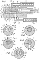
- the nozzle head I of a multi-component plastic injection molding machine is shown in longitudinal section. It has a housing 2 with a central nozzle mouthpiece 3, to which a valve valve 4 is rotatably assigned within the housing 2, which in turn is coupled to an actuator 5 at the rear end of the housing 2.
- the valve tap 4 is rotatably mounted in the housing 2 about an axis 7-7 running parallel to the longitudinal center axis 6-6 of the nozzle head I, the two axes 6-6 and 7-7 being arranged eccentrically relative to one another by the dimension 8.
- the valve cock 4 is designed as a turret body which can be rotated about the axis 7-7 within the housing 2 and which contains several, for example two, longitudinal channels 9 and 10, the axes II and 12 of which have a corresponding radial distance from the longitudinal axis 7-7 , which in turn corresponds to the eccentricity 8 between the longitudinal axis 6-6 of the housing 2 and the longitudinal axis 7-7 of the valve tap or turret body 4.
- Each longitudinal channel 9 and 10 opens at the flat face or end face 13 of the valve cock or turret body 4 facing the nozzle mouthpiece 3, this face or end face 13 being opposite a flat locking surface 14 within the housing 2, on which the nozzle mouthpiece 3 opens into the housing 2.
- each longitudinal channel 9 and 10 of the valve tap or turret body 4 can be placed in alignment with the nozzle mouthpiece 3 so that it corresponds directly to it.
- the longitudinal channel 9, is connected to an annular channel 15, which is incorporated into the outer surface of the valve tap or turret body 4.
- the longitudinal channel 10 has a permanent connection with an annular channel 16, which is also molded into the outer surface of the valve tap or turret body 4.
- the two ring channels 15 and 16 are located in different length ranges on the outer circumference of the valve tap or turret body 4. Each of them corresponds to a radial connecting channel 17 or 18 in the housing 2, on which in turn the injection cylinder 19 or 20 of two different plasticizing units 21 and 22 is connected.
- the two longitudinal channels 9 and 10 of the valve tap or turret body 4 can be constantly subjected to plastic melt from the plasticizing units 21 and 22, the expulsion of these plastic melts from the nozzle mouthpiece 3 taking place when the respective longitudinal channel 9 or 10 corresponds to it.
- These grooves 23 and 24 run from the mouth end of the longitudinal channel 9 and 10 in question in the rotational or circumferential direction of the valve tap or turret body 4 and consequently adjoin the locking surface 14 of the housing 2.
- the elongated grooves 23 and 24 are designed as concentric about the axis of rotation 7-7 of the valve tap or turret 4 ring segments and can have such a length dimension that the mutually facing ends of two in the circumferential direction of the valve tap or turret body 4 of adjacent or successive grooves 23 and 24 are only separated from one another by an almost cutting-like web 25 and 26.
- valve tap or turret body 4 with more than two longitudinal channels 9 and 10, for example three such longitudinal channels 9, 10, 27, as indicated in FIG. 6.
- three different grooves 23, 24, 28 oriented in the same direction of rotation are then also present on the end or end face of the valve tap or turret body 4, the ends of which are separated from one another by the cutting-like webs 25, 26, 29 are.
- the nozzle head can work with three different injection cylinders or plasticizing units, i.e. three different plastic components can be driven out one after the other through the nozzle mouthpiece 3, wherein two of these components can also be fed into the nozzle mouthpiece 3 at the same time, if necessary.
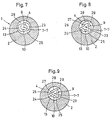
- the grooves 23, 24 and 23, 24, 28 on the end face 13 of the valve tap or turret body 4 may also form ring segments extending in a spiral arm-like manner to the axis of rotation of the turret body, as is the case in FIGS. 7 and 8 is shown.
- the mutually adjacent ends of two successive ring segments can also overlap one another in regions, based on the direction of rotation of the valve tap or turret body 5, as can be clearly seen in FIG. 8.
- the possibility would be offered, in a simple way temporarily and at the same time differently Feed plastic components to the nozzle mouthpiece 3.
- the grooves 23 and 24 or 23, 24, 28 also need not have a curved configuration in the direction of rotation of the valve tap or turret body 4. Rather, they can also be oriented straight, but secantially relative to the circumference of the turret body, as shown in FIG. 9, their ends, each connected to a longitudinal channel 9, 10 or 9, 10, 27, on a smaller one Circular arcs lie as their ends facing away from them.
- grooves 23, 24 and 23, 24, 28 such that they gradually taper towards their end remote from the mouth region of the longitudinal channels 9, 10 and 9, 10, 27, respectively tapered end runs directly next to the end of the subsequent groove adjoining a longitudinal channel, as can also be seen in FIG. 9.
- the shape of the grooves means that the manner in which the nozzle mouthpiece 3 is loaded with various plastic components can be influenced as required.
Landscapes
- Engineering & Computer Science (AREA)
- Manufacturing & Machinery (AREA)
- Mechanical Engineering (AREA)
- Injection Moulding Of Plastics Or The Like (AREA)
- Coating Apparatus (AREA)
- Extrusion Moulding Of Plastics Or The Like (AREA)
- Nozzles (AREA)
- Processing And Handling Of Plastics And Other Materials For Molding In General (AREA)
- Closures For Containers (AREA)
- Sampling And Sample Adjustment (AREA)
Priority Applications (1)
| Application Number | Priority Date | Filing Date | Title |
|---|---|---|---|
| AT87102431T ATE55313T1 (de) | 1986-02-27 | 1987-02-20 | Duesenkopf zum wahlweisen austreiben mehrerer verschiedener kunststoffkomponenten aus einem zentralen duesenmundstueck. |
Applications Claiming Priority (2)
| Application Number | Priority Date | Filing Date | Title |
|---|---|---|---|
| DE3606298 | 1986-02-27 | ||
| DE19863606298 DE3606298A1 (de) | 1986-02-27 | 1986-02-27 | Duesenkopf zum wahlweisen austreiben mehrerer verschiedener kunststoffkomponenten aus einem zentralen duesenmundstueck |
Publications (3)
| Publication Number | Publication Date |
|---|---|
| EP0234522A2 EP0234522A2 (de) | 1987-09-02 |
| EP0234522A3 EP0234522A3 (en) | 1988-12-21 |
| EP0234522B1 true EP0234522B1 (de) | 1990-08-08 |
Family
ID=6295023
Family Applications (1)
| Application Number | Title | Priority Date | Filing Date |
|---|---|---|---|
| EP87102431A Expired - Lifetime EP0234522B1 (de) | 1986-02-27 | 1987-02-20 | Düsenkopf zum wahlweisen Austreiben mehrerer verschiedener Kunststoffkomponenten aus einem zentralen Düsenmundstück |
Country Status (6)
| Country | Link |
|---|---|
| EP (1) | EP0234522B1 (enExample) |
| JP (1) | JPS62204914A (enExample) |
| AT (1) | ATE55313T1 (enExample) |
| AU (1) | AU6915387A (enExample) |
| BR (1) | BR8700937A (enExample) |
| DE (2) | DE3606298A1 (enExample) |
Families Citing this family (3)
| Publication number | Priority date | Publication date | Assignee | Title |
|---|---|---|---|---|
| US5102323A (en) * | 1988-08-31 | 1992-04-07 | American National Can Company | Plastic resin multi-layer co-extrusion extruder with multi-port plug for selecting order of layers |
| DE3912426A1 (de) * | 1989-04-12 | 1990-10-18 | Mannesmann Ag | Verfahren und vorrichtung zum herstellen von mehrkomponentenspritzgiessteilen |
| EP1369216A1 (de) | 2002-06-04 | 2003-12-10 | Windsor Kunststofftechnologie GmbH | Coinjections-Einheit für Spritzgiessmaschinen |
Family Cites Families (4)
| Publication number | Priority date | Publication date | Assignee | Title |
|---|---|---|---|---|
| FR802039A (fr) * | 1935-06-12 | 1936-08-25 | Robinet perfectionné | |
| FR2257407B1 (enExample) * | 1973-09-21 | 1976-05-14 | Billion Sa | |
| GB2024991B (en) * | 1978-07-05 | 1982-10-13 | Ewarts Ltd | Gas taps |
| DE3618616C1 (de) * | 1986-06-03 | 1987-08-20 | Battenfeld Maschfab | Spritzduese zur Herstellung von Formteilen aus drei verschiedenen Kunststoffkomponenten |
-
1986
- 1986-02-27 DE DE19863606298 patent/DE3606298A1/de not_active Withdrawn
-
1987
- 1987-02-20 DE DE8787102431T patent/DE3764113D1/de not_active Expired - Lifetime
- 1987-02-20 AT AT87102431T patent/ATE55313T1/de not_active IP Right Cessation
- 1987-02-20 EP EP87102431A patent/EP0234522B1/de not_active Expired - Lifetime
- 1987-02-23 AU AU69153/87A patent/AU6915387A/en not_active Abandoned
- 1987-02-26 JP JP62041580A patent/JPS62204914A/ja active Granted
- 1987-02-26 BR BR8700937A patent/BR8700937A/pt unknown
Also Published As
| Publication number | Publication date |
|---|---|
| AU6915387A (en) | 1987-09-03 |
| ATE55313T1 (de) | 1990-08-15 |
| DE3764113D1 (de) | 1990-09-13 |
| JPH0455566B2 (enExample) | 1992-09-03 |
| DE3606298A1 (de) | 1987-09-03 |
| JPS62204914A (ja) | 1987-09-09 |
| EP0234522A3 (en) | 1988-12-21 |
| EP0234522A2 (de) | 1987-09-02 |
| BR8700937A (pt) | 1987-12-15 |
Similar Documents
| Publication | Publication Date | Title |
|---|---|---|
| EP0043543B1 (de) | Vorrichtung zum Herstellen von Mehrschichtformteilen aus thermoplastischen Kunststoffen | |
| EP0261350B1 (de) | Vorrichtung zur Herstellung von Kunststoff-Formkörpern | |
| DE3734547C2 (enExample) | ||
| DE2904127C2 (enExample) | ||
| DE2510127A1 (de) | Strangpresskopf zum herstellen eines aus zwei konzentrischen, mit ihren schweissnaehten zueinander versetzten schichten bestehenden hohlstranges aus thermoplastischem werkstoff | |
| EP0719587A2 (de) | Brausekopf, insbesondere für eine Handbrause | |
| DE2027910A1 (de) | Vorrichtung zum Verarbeiten von Kunststoffen | |
| DE3922240C2 (de) | Drehschieberweiche | |
| EP1380400B1 (de) | Spritzgiessdüse mit Nadelverschluss und seitlichen Austrittsöffnungen | |
| EP0262470B1 (de) | Spritzkopf zum Herstellen von Mehrschicht-Formkörpern aus thermoplastischem Kunststoffmaterial | |
| EP0118692A2 (de) | Pinole für den Dorn eines Schlauchkopfes zur Herstellung von Schlauchabschnitten oder Schläuchen aus thermoplastischem Kunststoff | |
| DE2416686C3 (de) | Mischkopf zum Mischen von wenigstens zwei fließfähigen Materialkomponenten | |
| EP0093958B1 (de) | Mischkopf zum Vermischen mindestens zweier fliessfähiger, bei ihrer Reaktion vorzugsweise Schaumstoff bildender Komponenten | |
| EP0303590B1 (de) | Einrichtung zum Umspritzen einer Seele, inbesondere eines elektrischen Leiters | |
| EP0800907A1 (de) | Nadelverschlussdüse mit Spritzgiessform und Verschlussnadel | |
| EP0234522B1 (de) | Düsenkopf zum wahlweisen Austreiben mehrerer verschiedener Kunststoffkomponenten aus einem zentralen Düsenmundstück | |
| EP0566951B1 (de) | Mischkopf zum Vermischen von mindestens zwei Kunststoff bildenden, fliessfähigen Reaktionskomponenten | |
| EP2199055A1 (de) | Vorrichtung zum Anspritzen von Kunststoffformteilen | |
| EP0499069A1 (de) | Mischvorrichtung zur Verarbeitung flüssiger Mehrkomponenten-Kunststoffe, insbesondere Polyurethan | |
| DE3107214A1 (de) | Schneckenmaschine zur herstellung von mehrfarbigen kunststoffteilen | |
| DE1779319B1 (de) | Vorrichtung zum kontinuierlichen strangpressen eines schlauchfoermigen netzes | |
| DE69207329T2 (de) | Vorrichtung mit mehreren parallelen Düsen zum dreifarbig Co-extrudieren | |
| DE3940954C2 (enExample) | ||
| DE2639665C2 (de) | Strangpreßkopf zum Herstellen eines hohlen Stranges aus thermoplastischem Kunststoff | |
| AT391294B (de) | Spritzgussduese |
Legal Events
| Date | Code | Title | Description |
|---|---|---|---|
| PUAI | Public reference made under article 153(3) epc to a published international application that has entered the european phase |
Free format text: ORIGINAL CODE: 0009012 |
|
| 17P | Request for examination filed |
Effective date: 19870311 |
|
| AK | Designated contracting states |
Kind code of ref document: A2 Designated state(s): AT BE CH DE FR GB IT LI NL SE |
|
| RAP1 | Party data changed (applicant data changed or rights of an application transferred) |
Owner name: BATTENFELD GMBH |
|
| PUAL | Search report despatched |
Free format text: ORIGINAL CODE: 0009013 |
|
| AK | Designated contracting states |
Kind code of ref document: A3 Designated state(s): AT BE CH DE FR GB IT LI NL SE |
|
| 17Q | First examination report despatched |
Effective date: 19891110 |
|
| GRAA | (expected) grant |
Free format text: ORIGINAL CODE: 0009210 |
|
| AK | Designated contracting states |
Kind code of ref document: B1 Designated state(s): AT BE CH DE FR GB IT LI NL SE |
|
| PG25 | Lapsed in a contracting state [announced via postgrant information from national office to epo] |
Ref country code: SE Free format text: THE PATENT HAS BEEN ANNULLED BY A DECISION OF A NATIONAL AUTHORITY Effective date: 19900808 Ref country code: GB Effective date: 19900808 |
|
| REF | Corresponds to: |
Ref document number: 55313 Country of ref document: AT Date of ref document: 19900815 Kind code of ref document: T |
|
| REF | Corresponds to: |
Ref document number: 3764113 Country of ref document: DE Date of ref document: 19900913 |
|
| ITF | It: translation for a ep patent filed | ||
| ET | Fr: translation filed | ||
| PGFP | Annual fee paid to national office [announced via postgrant information from national office to epo] |
Ref country code: AT Payment date: 19910121 Year of fee payment: 5 |
|
| PGFP | Annual fee paid to national office [announced via postgrant information from national office to epo] |
Ref country code: FR Payment date: 19910122 Year of fee payment: 5 |
|
| GBV | Gb: ep patent (uk) treated as always having been void in accordance with gb section 77(7)/1977 [no translation filed] | ||
| ITTA | It: last paid annual fee | ||
| PG25 | Lapsed in a contracting state [announced via postgrant information from national office to epo] |
Ref country code: LI Effective date: 19910228 Ref country code: CH Effective date: 19910228 Ref country code: BE Effective date: 19910228 |
|
| PGFP | Annual fee paid to national office [announced via postgrant information from national office to epo] |
Ref country code: DE Payment date: 19910412 Year of fee payment: 5 |
|
| PLBE | No opposition filed within time limit |
Free format text: ORIGINAL CODE: 0009261 |
|
| STAA | Information on the status of an ep patent application or granted ep patent |
Free format text: STATUS: NO OPPOSITION FILED WITHIN TIME LIMIT |
|
| 26N | No opposition filed | ||
| PG25 | Lapsed in a contracting state [announced via postgrant information from national office to epo] |
Ref country code: NL Effective date: 19910901 |
|
| NLV4 | Nl: lapsed or anulled due to non-payment of the annual fee | ||
| REG | Reference to a national code |
Ref country code: CH Ref legal event code: PL |
|
| PG25 | Lapsed in a contracting state [announced via postgrant information from national office to epo] |
Ref country code: AT Effective date: 19920220 |
|
| PG25 | Lapsed in a contracting state [announced via postgrant information from national office to epo] |
Ref country code: FR Effective date: 19921030 |
|
| PG25 | Lapsed in a contracting state [announced via postgrant information from national office to epo] |
Ref country code: DE Effective date: 19921103 |
|
| REG | Reference to a national code |
Ref country code: FR Ref legal event code: ST |
|
| PG25 | Lapsed in a contracting state [announced via postgrant information from national office to epo] |
Ref country code: IT Free format text: LAPSE BECAUSE OF NON-PAYMENT OF DUE FEES;WARNING: LAPSES OF ITALIAN PATENTS WITH EFFECTIVE DATE BEFORE 2007 MAY HAVE OCCURRED AT ANY TIME BEFORE 2007. THE CORRECT EFFECTIVE DATE MAY BE DIFFERENT FROM THE ONE RECORDED. Effective date: 20050220 |