EP0234522B1 - Nozzle head for optionally expelling a plurality of different plastic components from a central nozzle piece - Google Patents
Nozzle head for optionally expelling a plurality of different plastic components from a central nozzle piece Download PDFInfo
- Publication number
- EP0234522B1 EP0234522B1 EP87102431A EP87102431A EP0234522B1 EP 0234522 B1 EP0234522 B1 EP 0234522B1 EP 87102431 A EP87102431 A EP 87102431A EP 87102431 A EP87102431 A EP 87102431A EP 0234522 B1 EP0234522 B1 EP 0234522B1
- Authority
- EP
- European Patent Office
- Prior art keywords
- turret body
- nozzle
- nozzle head
- grooves
- nozzle mouthpiece
- Prior art date
- Legal status (The legal status is an assumption and is not a legal conclusion. Google has not performed a legal analysis and makes no representation as to the accuracy of the status listed.)
- Expired - Lifetime
Links
Images
Classifications
-
- B—PERFORMING OPERATIONS; TRANSPORTING
- B29—WORKING OF PLASTICS; WORKING OF SUBSTANCES IN A PLASTIC STATE IN GENERAL
- B29C—SHAPING OR JOINING OF PLASTICS; SHAPING OF MATERIAL IN A PLASTIC STATE, NOT OTHERWISE PROVIDED FOR; AFTER-TREATMENT OF THE SHAPED PRODUCTS, e.g. REPAIRING
- B29C45/00—Injection moulding, i.e. forcing the required volume of moulding material through a nozzle into a closed mould; Apparatus therefor
- B29C45/16—Making multilayered or multicoloured articles
- B29C45/1603—Multi-way nozzles specially adapted therefor
- B29C45/1606—Multi-way nozzles specially adapted therefor using a rotatable valve
Definitions
- the invention relates to a nozzle head for selectively driving out several different plastic components from a central nozzle mouthpiece, in which a valve tap is rotatably arranged in the housing carrying or having the nozzle mouthpiece, which valve valve contains various flow channels, each of which contains a specific injection cylinder or the like from several plasticizing units the nozzle mouthpiece is connectable.
- valve tap is rotatably mounted in the housing about an axis which extends essentially transversely to the longitudinal axis of the nozzle mouthpiece.
- valve valve not only requires the associated actuator to be arranged on the side next to the nozzle head, but also impairs the optimal assignment of the various plasticizing units or injection cylinders to the nozzle head.
- Another inadequacy of the known nozzle heads is that the mass flows from the individual plasticizing units or injection cylinders can only be introduced into the nozzle mouthpiece one after the other, so that one mass flow is completely shut off before the next mass flow is introduced into the nozzle mouthpiece can. In many cases, however, it is desirable or a condition that, at least temporarily, a simultaneous supply of material from two different mass flows enters the nozzle mouthpiece.
- the invention is therefore based on the one hand the object to improve a nozzle head of the type specified in such a way that the actuator for the valve tap does not impair the optimal assignment of the various plasticizing units or injection cylinders.
- the valve tap is designed as a turret body which is rotatably mounted axially parallel to the nozzle mouthpiece in the housing, and that longitudinal channels arranged concentrically around its axis of rotation are provided in the turret body that these longitudinal channels on the one hand face the nozzle mouthpiece End or end face of the turret body open and an adjoining locking surface of the housing are turned, while on the other hand they are each connected to a ring channel and these ring channels are in different lengths on the outer circumference of the turret body, and that each ring channel is always with a spray cylinder or the like or an injection unit is held in flow connection, while each longitudinal channel can be adjusted individually in the aligned position with the nozzle mouthpiece.
- each longitudinal channel on the front or. End surface of the turret body in each case opens into an elongated groove running parallel to this at one end, the grooves extending from this end in the rotational or circumferential direction of the turret body to the locking surface of the housing.
- the grooves are designed as ring segments oriented concentrically around the axis of rotation of the turret body and, according to claim 4, the ends of two adjacent or successive grooves in the circumferential direction of the turret body are connected to the nozzle mouthpiece at the same time, a simultaneous supply of Material from several different mass flows into the nozzle mouthpiece can be easily accomplished.
- a particularly advantageous further training measure in this sense is seen in claim 5 in that the mutually facing ends of two adjacent or successive grooves in the circumferential direction of the turret body are only separated from one another by an almost cutting-like web.
- the grooves are designed as a spiral arm to the axis of rotation of the turret body ring segments, in which according to claim 7, the adjacent ends of two successive ring segments overlap each other, based on the circumferential direction of the turret body.
- the grooves can also run straight, but can be oriented secantially relative to the circumference of the turret body, their ends, each connected to a longitudinal channel, lying on a smaller circular arc than their ends turned away from them.
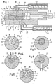
- the nozzle head I of a multi-component plastic injection molding machine is shown in longitudinal section. It has a housing 2 with a central nozzle mouthpiece 3, to which a valve valve 4 is rotatably assigned within the housing 2, which in turn is coupled to an actuator 5 at the rear end of the housing 2.
- the valve tap 4 is rotatably mounted in the housing 2 about an axis 7-7 running parallel to the longitudinal center axis 6-6 of the nozzle head I, the two axes 6-6 and 7-7 being arranged eccentrically relative to one another by the dimension 8.
- the valve cock 4 is designed as a turret body which can be rotated about the axis 7-7 within the housing 2 and which contains several, for example two, longitudinal channels 9 and 10, the axes II and 12 of which have a corresponding radial distance from the longitudinal axis 7-7 , which in turn corresponds to the eccentricity 8 between the longitudinal axis 6-6 of the housing 2 and the longitudinal axis 7-7 of the valve tap or turret body 4.
- Each longitudinal channel 9 and 10 opens at the flat face or end face 13 of the valve cock or turret body 4 facing the nozzle mouthpiece 3, this face or end face 13 being opposite a flat locking surface 14 within the housing 2, on which the nozzle mouthpiece 3 opens into the housing 2.
- each longitudinal channel 9 and 10 of the valve tap or turret body 4 can be placed in alignment with the nozzle mouthpiece 3 so that it corresponds directly to it.
- the longitudinal channel 9, is connected to an annular channel 15, which is incorporated into the outer surface of the valve tap or turret body 4.
- the longitudinal channel 10 has a permanent connection with an annular channel 16, which is also molded into the outer surface of the valve tap or turret body 4.
- the two ring channels 15 and 16 are located in different length ranges on the outer circumference of the valve tap or turret body 4. Each of them corresponds to a radial connecting channel 17 or 18 in the housing 2, on which in turn the injection cylinder 19 or 20 of two different plasticizing units 21 and 22 is connected.
- the two longitudinal channels 9 and 10 of the valve tap or turret body 4 can be constantly subjected to plastic melt from the plasticizing units 21 and 22, the expulsion of these plastic melts from the nozzle mouthpiece 3 taking place when the respective longitudinal channel 9 or 10 corresponds to it.
- These grooves 23 and 24 run from the mouth end of the longitudinal channel 9 and 10 in question in the rotational or circumferential direction of the valve tap or turret body 4 and consequently adjoin the locking surface 14 of the housing 2.
- the elongated grooves 23 and 24 are designed as concentric about the axis of rotation 7-7 of the valve tap or turret 4 ring segments and can have such a length dimension that the mutually facing ends of two in the circumferential direction of the valve tap or turret body 4 of adjacent or successive grooves 23 and 24 are only separated from one another by an almost cutting-like web 25 and 26.
- valve tap or turret body 4 with more than two longitudinal channels 9 and 10, for example three such longitudinal channels 9, 10, 27, as indicated in FIG. 6.
- three different grooves 23, 24, 28 oriented in the same direction of rotation are then also present on the end or end face of the valve tap or turret body 4, the ends of which are separated from one another by the cutting-like webs 25, 26, 29 are.
- the nozzle head can work with three different injection cylinders or plasticizing units, i.e. three different plastic components can be driven out one after the other through the nozzle mouthpiece 3, wherein two of these components can also be fed into the nozzle mouthpiece 3 at the same time, if necessary.
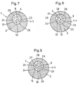
- the grooves 23, 24 and 23, 24, 28 on the end face 13 of the valve tap or turret body 4 may also form ring segments extending in a spiral arm-like manner to the axis of rotation of the turret body, as is the case in FIGS. 7 and 8 is shown.
- the mutually adjacent ends of two successive ring segments can also overlap one another in regions, based on the direction of rotation of the valve tap or turret body 5, as can be clearly seen in FIG. 8.
- the possibility would be offered, in a simple way temporarily and at the same time differently Feed plastic components to the nozzle mouthpiece 3.
- the grooves 23 and 24 or 23, 24, 28 also need not have a curved configuration in the direction of rotation of the valve tap or turret body 4. Rather, they can also be oriented straight, but secantially relative to the circumference of the turret body, as shown in FIG. 9, their ends, each connected to a longitudinal channel 9, 10 or 9, 10, 27, on a smaller one Circular arcs lie as their ends facing away from them.
- grooves 23, 24 and 23, 24, 28 such that they gradually taper towards their end remote from the mouth region of the longitudinal channels 9, 10 and 9, 10, 27, respectively tapered end runs directly next to the end of the subsequent groove adjoining a longitudinal channel, as can also be seen in FIG. 9.
- the shape of the grooves means that the manner in which the nozzle mouthpiece 3 is loaded with various plastic components can be influenced as required.
Abstract
Description
Die Erfindung betrifft einen Düsenkopf zum wahlweisen Austreiben mehrerer verschiedener Kunststoffkomponenten aus einem zentralen Düsenmundstück, bei welchem in dem das Düsenmundstück tragenden bzw. aufweisenden Gehäuse ein Ventilhahn drehbar angeordnet ist, der verschiedene Durchströmkanäle enthält, über deren jeden ein bestimmter Spritzzylinder oder dergleichen von mehreren Plastifiziereinheiten mit dem Düsenmundstück in Verbindung bringbar ist.The invention relates to a nozzle head for selectively driving out several different plastic components from a central nozzle mouthpiece, in which a valve tap is rotatably arranged in the housing carrying or having the nozzle mouthpiece, which valve valve contains various flow channels, each of which contains a specific injection cylinder or the like from several plasticizing units the nozzle mouthpiece is connectable.
Düsenköpfe dieser Funktionsweise und Bauart sind bereits bekannt durch die DE-OS 18 14 343 und die DE-AS 24 45 107. Hierbei ist jeweils der Ventilhahn im Gehäuse um eine Achse drehverstellbar gelagert, die sich im wesentlichen quer zur Längsachse des Düsenmundstücks erstreckt.Nozzle heads of this function and type are already known from DE-OS 18 14 343 and DE-AS 24 45 107. In this case, the valve tap is rotatably mounted in the housing about an axis which extends essentially transversely to the longitudinal axis of the nozzle mouthpiece.
Diese Anordnung des Ventilhahns erfordert nicht nur die Anordnung des zugehörigen Stellantriebs seitlich neben dem Düsenkopf, sondern sie beeinträchtigt auch die optimale Zuordnung der verschiedenen Plastifiziereinheiten bzw. Spritzzylinder zum Düsenkopf.This arrangement of the valve valve not only requires the associated actuator to be arranged on the side next to the nozzle head, but also impairs the optimal assignment of the various plasticizing units or injection cylinders to the nozzle head.
Eine andere Unzulänglichkeit der bekannten Düsenköpfe besteht aber auch darin, daß die Massenströme aus den einzelnen Plastifiziereinheiten bzw. Spritzzylindern immer nur nacheinander in das Düsenmundstück eingeführt werden können, daß also jeweils der eine Massenstrom völlig abgesperrt wird, bevor der nächste Massenstrom in das Düsenmundstück eingeleitet werden kann. In vielen Fällen ist es jedoch erwünscht oder Bedingung, daß wenigstens zeitweilig eine gleichzeitige Materialzufuhr aus zwei verschiedenen Massenströmen in das Düsenmundstück gelangt.Another inadequacy of the known nozzle heads is that the mass flows from the individual plasticizing units or injection cylinders can only be introduced into the nozzle mouthpiece one after the other, so that one mass flow is completely shut off before the next mass flow is introduced into the nozzle mouthpiece can. In many cases, however, it is desirable or a condition that, at least temporarily, a simultaneous supply of material from two different mass flows enters the nozzle mouthpiece.
Der Erfindung liegt daher einerseits die Aufgabe zugrunde, einen Düsenkopf der eingangs angegebenen Bauart so zu verbessern, daß der Stellantrieb für den Ventilhahn die optimale Zuordnung der verschiedenen Plastifiziereinheiten bzw. Spritzzylinder nicht beeinträchtigt. Darüber hinaus ist es aber auch die Aufgabe der Erfindung, den gattungsgemäßen Düsenkopf so auszubilden, daß er es möglich macht, zumindest zeitweilig Kunststoffmaterial aus zwei verschiedenen Masseströmen dem Düsenmundstück zuzuführen.The invention is therefore based on the one hand the object to improve a nozzle head of the type specified in such a way that the actuator for the valve tap does not impair the optimal assignment of the various plasticizing units or injection cylinders. In addition, it is also the object of the invention to design the generic nozzle head in such a way that it makes it possible, at least temporarily, to supply plastic material from two different mass flows to the nozzle mouthpiece.
Zur Lösung der Hauptaufgabe ist nach dem Kennzeichen des Anspruchs I erfindungsgemäß vorgesehen, daß der Ventilhahn als achsparallel zum Düsenmundstück im Gehäuse verdrehbar gelagerter Revolverkörper ausgebildet ist, daß im Revolverkörper konzentrisch um seine Drehachse angeordnete Längskanäle vorgesehen sind, daß diese Längskanäle einerseits an einer dem Düsenmundstück zugewendeten Stirn- bzw. Endfläche des Revolverkörpers münden und einer daran anliegenden Sperrfläche des Gehäuses zugewendet sind, während sie andererseits je an einen Ringkanal angeschlossen sind und diese Ringkanäle sich in verschiedenen Längenbereichen am Außenumfang des Revolverkörpers befinden, und daß jeder Ringkanal ständig mit je einem Spritzzylinder oder dergleichen bzw. einer Spritzeinheit in Strömungsverbindung gehalten ist, während jeder Längskanal einzeln in Fluchtlage mit dem Düsenmundstück stellbar ist.To solve the main task according to the characterizing part of claim I, it is provided according to the invention that the valve tap is designed as a turret body which is rotatably mounted axially parallel to the nozzle mouthpiece in the housing, and that longitudinal channels arranged concentrically around its axis of rotation are provided in the turret body that these longitudinal channels on the one hand face the nozzle mouthpiece End or end face of the turret body open and an adjoining locking surface of the housing are turned, while on the other hand they are each connected to a ring channel and these ring channels are in different lengths on the outer circumference of the turret body, and that each ring channel is always with a spray cylinder or the like or an injection unit is held in flow connection, while each longitudinal channel can be adjusted individually in the aligned position with the nozzle mouthpiece.
Durch diese Maßnahmen wird zugleich eine baulich günstige Ausgestaltung des Düsenkopfes erhalten.These measures also result in a structurally advantageous configuration of the nozzle head.
Zur Lösung der weiteren Aufgabe ist erfindungsgemäß nach Anspruch 2 vorgesehen, daß jeder Längskanal an der Stirn-bzw. Endfläche des Revolverkörpers in je eine parallel zu dieser verlaufende längliche Nut an einem Ende einmündet, wobei die Nuten von diesem Ende aus in Dreh- bzw. Umfangsrichtung des Revolverkörpers verlaufend, an die Sperrfläche des Gehäuses anschließen. Wenn dabei gemäß Anspruch 3 die Nuten als konzentrisch um die Drehachse des Revolverkörpers orientierte Ringsegmente gestaltet sind sowie gemäß Anspruch 4 gleichzeitig die einander zugewendeten Enden zweier in Umfangsrichtung des Revolverkörpers benachbarter bzw. aufeinanderfolgender Nuten mit dem Düsenmundstück in Verbindung bringbar sind, kann eine gleichzeitige Zuführung von Material aus mehreren verschiedenen Massenströmen in das Düsenmundstück problemlos bewerkstelligt werden.To solve the further problem, the invention provides according to
Eine besonders vorteilhafte Weiterbildungsmaßnahme wird in diesem Sinne nach Anspruch 5 darin gesehen, daß die einander zugewendeten Enden zweier in Umfangsrichtung des Revolverkörpers benachbarter bzw. aufeinanderfolgender Nuten lediglich durch einen nahezu schneidenartigen Steg voneinander getrennt sind.A particularly advantageous further training measure in this sense is seen in
Nach Anspruch 6 liegt es aber auch im Rahmen der Erfindung, daß die Nuten als spiralarmartig zur Drehachse des Revolverkörpers verlaufende Ringsegmente gestaltet sind, bei denen gemäß Anspruch 7 die einander benachbarten Enden zweier aufeinanderfolgender Ringsegmente sich, bezogen auf die Umfangsrichtung des Revolverkörpers, gegenseitig überlappen.According to
Schließlich können nach Anspruch 9 die Nuten auch gerade verlaufen, aber sekantial relativ zum Umfang des Revolverkörpers orientiert sein, wobei ihre je mit einem Längskanal in Verbindung stehenden Enden auf einem kleineren Kreisbogen liegen als ihre davon abgewendeten Enden.Finally, according to
In der Zeichnung ist der Gegenstand der Erfindung in Ausführungsbeispielen dargestellt. Es zeigen
- Figur I in schematisch vereinfachter Längsschnitt-Darstellung einen erfindungsgemäßen Düsenkopf für Mehrkomponenten-Kunststoff-Spritzgießmaschinen,
Figur 2 einen Schnitt entlang der Linie 11-11 in Fig. 1,Figur 3 einen Schnitt entlang der Linie 111-111 in Fig. 1,Figur 4 einen Schnitt entlang der Linie IV-IV in Fig. 1,Figur 5 einen Schnitt entlang der Linie V-V in Fig. I,Figur 6 einen der Fig. 2 entsprechenden Schnitt durch eine abgewandelte Bauart eines erfindungsgemäßen Düsenkopfes,Figur 7 einen der Fig. 2 entsprechenden Schnitt durch eine weitere abgewandelte Bauart eines erfindungsgemäßen Düsenkopfes,Figur 8 einen der Fig. 6 entsprechenden Schnitt durch eine wieder andere Bauart eines erfindungsgemäßen Düsenkopfes undFigur 9 einen der Fig. 6 entsprechenden Schnitt durch eine noch andere Ausgestaltung eines erfindungsgemäßen Düsenkopfes.
- FIG. I shows a nozzle head according to the invention for multi-component plastic injection molding machines in a schematically simplified longitudinal section,
- FIG. 2 shows a section along the line 11-11 in FIG. 1,
- FIG. 3 shows a section along the line 111-111 in FIG. 1,
- FIG. 4 shows a section along the line IV-IV in FIG. 1,
- FIG. 5 shows a section along the line VV in FIG. I,
- 6 shows a section corresponding to FIG. 2 through a modified design of a nozzle head according to the invention,
- 7 shows a section corresponding to FIG. 2 through a further modified design of a nozzle head according to the invention,
- 8 shows a section corresponding to FIG. 6 through yet another design of a nozzle head according to the invention and
- 9 shows a section corresponding to FIG. 6 through yet another embodiment of a nozzle head according to the invention.
In Fig. I der Zeichnung ist im Längsschnitt der Düsenkopf I einer Mehrkomponenten-Kunststoff-Spritzgießmaschine dargestellt. Er weist ein Gehäuse 2 mit einem zentralen Düsenmundstück 3 auf, dem innerhalb des Gehäuses 2 ein Ventilhahn 4 drehbar zugeordnet ist, welcher wiederum am hinteren Ende des Gehäuses 2 mit einem Stellantrieb 5 gekuppelt ist. Der Ventilhahn 4 ist dabei um eine parallel zur Längsmittelachse 6-6 des Düsenkopfes I verlaufende Achse 7-7 im Gehäuse 2 drehbar gelagert, wobei die beiden Achsen 6-6 und 7-7 relativ zueinander um das Maß 8 exzentrisch angeordnet sind. Der Ventilhahn 4 ist dabei als ein um die Achse 7-7 innerhalb des Gehäuses 2 verdrehbar angeordneter Revolverkörper ausgelegt, der mehrere, bspw. zwei Längskanäle 9 und 10 enthält, deren Achsen II bzw. 12 übereinstimmenden radialen Abstand von der Längsachse 7-7 aufweisen, welcher wiederum der Exzentrizität 8 zwischen der Längsachse 6-6 des Gehäuses 2 und der Längsachse 7-7 des Ventilhahns bzw. Revolverkörpers 4 entspricht.In Fig. I of the drawing, the nozzle head I of a multi-component plastic injection molding machine is shown in longitudinal section. It has a
Jeder Längskanal 9 und 10 mündet dabei an der dem Düsenmundstück 3 zugewendeten, ebenen Stirn- bzw. Endfläche 13 des Ventilhahns bzw. Revolverkörpers 4, wobei diese Stirn- bzw. Endfläche 13 einer ebenen Sperrfläche 14 innerhalb des Gehäuses 2 gegenüberliegt, an welcher das Düsenmundstück 3 im Gehäuse 2 ausmündet.Each
Durch Drehung mittels des Stellantriebs 5 kann jeder Längskanal 9 und 10 des Ventilhahns bzw. Revolverkörpers 4 für sich allein in Fluchtlage mit dem Düsenmundstück 3 gestellt werden, so daß er mit diesem unmittelbar korrespondiert.By turning by means of the
Der Längskanal 9 ist andererseits an einen Ringkanal 15 angeschlossen, welcher in die Mantelfläche des Ventilhahns bzw. Revolverkörpers 4 eingearbeitet ist. In gleicher Weise hat der Längskanal 10 eine ständige Verbindung mit einem Ringkanal 16, der ebenfalls in die Mantelfläche des Ventilhahns bzw. Revolverkörpers 4 eingeformt ist. Die beiden Ringkanäle 15 und 16 befinden sich dabei in verschiedenen Längenbereichen am Außenumfang des Ventilhahns bzw. Revolverkörpers 4. Jeder derselben korrespondiert mit einem radialen Verbindungskanal 17 bzw. 18 im Gehäuse 2, an den wiederum der Spritzzylinder 19 bzw. 20 zweier verschiedener Plastifiziereinheiten 21 und 22 angeschlossen ist.The
Die beiden Längskanäle 9 und 10 des Ventilhahns bzw. Revolverkörpers 4 können ständig mit Kunststoffschmelze von den Plastifiziereinheiten 21 und 22 beaufschlagt werden, wobei das Austreiben dieser Kunststoffschmelzen aus dem Düsenmundstück 3 jeweils dann stattfindet, wenn der betreffende Längskanal 9 bzw. 10 mit ihm korrespondiert.The two
Damit das Austreiben verschiedener Kunststoffkomponenten aus dem Düsenmundstück 3 praktisch ohne Zeitverzögerung unmittel bar aufeinanderfolgend stattfinden kann, ist es wichtig, daß jeder der beiden Längskanäle 9 und 10 an der Stirn- bzw. Endfläche 13 des Ventilhahns bzw. Revolverkörpers 4 in je eine parallel zu dieser verlaufende, längliche Nut 23 bzw. 24 einmündet. Diese Nuten 23 und 24 verlaufen dabei von dem Mündungsende des betreffenden Längskanals 9 und 10 aus in Dreh- bzw. Umfangsrichtung des Ventilhahns bzw. Revolverkörpers 4 und schließen sich folglich unmittelbar an die Sperrfläche 14 des Gehäuses 2 an.So that the expulsion of various plastic components from the
Aus Fig. 2 ergibt sich dabei, daß die länglichen Nuten 23 und 24 als konzentrisch um die Drehachse 7-7 des Ventilhahns bzw. Revolverkörpers 4 orientierte Ringsegmente gestaltet sind und eine solche Längenabmessung aufweisen können, daß die einander zugewendeten Enden zweier in Umfangsrichtung des Ventilhahns bzw. Revolverkörpers 4 benachbarter bzw. aufeinanderfolgender Nuten 23 und 24 lediglich durch einen nahezu schneidenartigen Steg 25 und 26 voneinander getrennt sind.From Fig. 2 it follows that the
Auf diese Art und Weise besteht die Möglichkeit, gleichzeitig die einander zugewendeten Enden zweier aufeinanderfolgender Nuten 23 und 24 mit dem Düsenmundstück 3 in Strömungsverbindung zu bringen, so daß auch gleichzeitig in dieses zwei verschiedene Kunststoffkomponenten eingespeist werden können, wenn dies für wünschenswert gehalten wird oder aber für die Bildung optimaler Spritzlinge erforderlich ist.In this way, there is the possibility of simultaneously bringing the facing ends of two
Selbstverständlich ist es auch möglich, den Ventilhahn bzw. Revolverkörper 4 mit mehr als zwei Längskanälen 9 und 10, bspw. drei solchen Längskanälen 9, 10, 27 zu versehen, wie dies in Fig. 6 angedeutet ist. Hierbei sind dann an der Stirn- bzw. Endfläche des Ventilhahns bzw. Revolverkörpers 4 in entsprechender Weise auch drei verschiedene, in Drehrichtung desselben orientierte Nuten 23, 24, 28 vorhanden, deren einander benachbarten Enden durch die schneidenartigen Stege 25, 26, 29 voneinander getrennt sind.Of course, it is also possible to provide the valve tap or
In diesem Falle kann der Düsenkopf mit drei verschiedenen Spritzzylindern bzw. Plastifiziereinheiten zusammenarbeiten, d.h. es können drei verschiedene Kunststoffkomponenten jeweils nacheinander durch das Düsenmundstück 3 ausgetrieben werden, wobei jeweils zwei dieser Komponenten bedarfsweise auch zeitgleich in das Düsenmundstück 3 zuführbar sind.In this case, the nozzle head can work with three different injection cylinders or plasticizing units, i.e. three different plastic components can be driven out one after the other through the
Erwähnenswert ist noch, daß die Nuten 23, 24 bzw. 23, 24, 28 an der Stirn-Endfläche 13 des Ventilhahns bzw. Revolverkörpers 4 gegebenenfalls auch spiralarmartig zur Drehachse des Revolverkörpers verlaufende Ringsegmente bilden können, wie das in den Fig. 7 und 8 dargestellt ist. Dabei können die einander benachbarten Enden zweier aufeinanderfolgender Ringsegmente sich, bezogen auf die Drehrichtung des Ventilhahns bzw. Revolverkörper 5, auch bereichsweise gegenseitig überlappen, wie das die Fig. 8 deutlich erkennen läßt. Auch hier durch wäre die Möglichkeit geboten, auf einfache Weise zeitweilig und gleichzeitig verschiedene Kunststoffkomponenten dem Düsenmundstück 3 zuzuführen.It is also worth mentioning that the
Die Nuten 23 und 24 bzw. 23, 24, 28 brauchen auch keine in Drehrichtung des Ventilhahns bzw. Revolverkörpers 4 gekrümmte Gestaltung zu haben. Vielmehr können sie gegebenenfalls auch gerade, aber sekantial relativ, zum Umfang des Revolverkörpers orientiert werden, wie das in Fig. 9 dargestellt ist, wobei ihre je mit einem Längskanal 9, 10 bzw. 9, 10, 27 in Verbindung stehenden Enden auf einem kleineren Kreisbogen liegen als ihre davon abgewendeten Enden.The
Schließlich wäre es aber auch noch möglich, die Nuten 23, 24 bzw. 23, 24, 28 so auszubilden, daß sich jeweils zu ihrem vom Mündungsbereich der Längskanäle 9, 10 bzw. 9, 10, 27 entfernten Ende hin allmählich verjüngen, wobei das verjüngte Ende unmittelbar neben dem an einen Längskanal anschließenden Endse der nachfolgenden Nut ausläuft, wie das ebenfalls die Fig. 9 erkennen läßt.Finally, it would also be possible to design the
Diese Querschnittsänderung der Nuten 23, 24 bzw. 23, 24, 28 kann natürlich auch dort verwirklicht werden, wo diese bogenförmig gekrümmt verlaufen, wie das in den Fig. 2, 6, 7 und 8 gezeigt ist.This cross-sectional change of the
Durch die Formgebung der Nuten kann also die Art und Weise der Beschickung des Düsenmundstücks 3 mit verschiedenen Kunststoffkomponenten bedarfsabhängig beeinflußt werden.The shape of the grooves means that the manner in which the
Claims (9)
Priority Applications (1)
| Application Number | Priority Date | Filing Date | Title |
|---|---|---|---|
| AT87102431T ATE55313T1 (en) | 1986-02-27 | 1987-02-20 | NOZZLE HEAD FOR CHOOSING SEVERAL DIFFERENT PLASTIC COMPONENTS FROM A CENTRAL NOZZLE MOUTHPIECE. |
Applications Claiming Priority (2)
| Application Number | Priority Date | Filing Date | Title |
|---|---|---|---|
| DE3606298 | 1986-02-27 | ||
| DE19863606298 DE3606298A1 (en) | 1986-02-27 | 1986-02-27 | NOZZLE HEAD FOR SELECTIVELY DRIVING OUT SEVERAL DIFFERENT PLASTIC COMPONENTS FROM A CENTRAL NOZZLE MOUTHPIECE |
Publications (3)
| Publication Number | Publication Date |
|---|---|
| EP0234522A2 EP0234522A2 (en) | 1987-09-02 |
| EP0234522A3 EP0234522A3 (en) | 1988-12-21 |
| EP0234522B1 true EP0234522B1 (en) | 1990-08-08 |
Family
ID=6295023
Family Applications (1)
| Application Number | Title | Priority Date | Filing Date |
|---|---|---|---|
| EP87102431A Expired - Lifetime EP0234522B1 (en) | 1986-02-27 | 1987-02-20 | Nozzle head for optionally expelling a plurality of different plastic components from a central nozzle piece |
Country Status (6)
| Country | Link |
|---|---|
| EP (1) | EP0234522B1 (en) |
| JP (1) | JPS62204914A (en) |
| AT (1) | ATE55313T1 (en) |
| AU (1) | AU6915387A (en) |
| BR (1) | BR8700937A (en) |
| DE (2) | DE3606298A1 (en) |
Families Citing this family (3)
| Publication number | Priority date | Publication date | Assignee | Title |
|---|---|---|---|---|
| US5102323A (en) * | 1988-08-31 | 1992-04-07 | American National Can Company | Plastic resin multi-layer co-extrusion extruder with multi-port plug for selecting order of layers |
| DE3912426A1 (en) * | 1989-04-12 | 1990-10-18 | Mannesmann Ag | METHOD AND DEVICE FOR PRODUCING MULTI-COMPONENT INJECTION MOLDING PARTS |
| EP1369216A1 (en) | 2002-06-04 | 2003-12-10 | Windsor Kunststofftechnologie GmbH | Coinjection unit for injection moulding machines |
Family Cites Families (4)
| Publication number | Priority date | Publication date | Assignee | Title |
|---|---|---|---|---|
| FR802039A (en) * | 1935-06-12 | 1936-08-25 | Sophisticated faucet | |
| FR2257407B1 (en) * | 1973-09-21 | 1976-05-14 | Billion Sa | |
| GB2024991B (en) * | 1978-07-05 | 1982-10-13 | Ewarts Ltd | Gas taps |
| DE3618616C1 (en) * | 1986-06-03 | 1987-08-20 | Battenfeld Maschfab | Spray nozzle for the production of molded parts from three different plastic components |
-
1986
- 1986-02-27 DE DE19863606298 patent/DE3606298A1/en not_active Withdrawn
-
1987
- 1987-02-20 AT AT87102431T patent/ATE55313T1/en not_active IP Right Cessation
- 1987-02-20 EP EP87102431A patent/EP0234522B1/en not_active Expired - Lifetime
- 1987-02-20 DE DE8787102431T patent/DE3764113D1/en not_active Expired - Lifetime
- 1987-02-23 AU AU69153/87A patent/AU6915387A/en not_active Abandoned
- 1987-02-26 JP JP62041580A patent/JPS62204914A/en active Granted
- 1987-02-26 BR BR8700937A patent/BR8700937A/en unknown
Also Published As
| Publication number | Publication date |
|---|---|
| JPH0455566B2 (en) | 1992-09-03 |
| JPS62204914A (en) | 1987-09-09 |
| BR8700937A (en) | 1987-12-15 |
| DE3764113D1 (en) | 1990-09-13 |
| ATE55313T1 (en) | 1990-08-15 |
| EP0234522A2 (en) | 1987-09-02 |
| DE3606298A1 (en) | 1987-09-03 |
| AU6915387A (en) | 1987-09-03 |
| EP0234522A3 (en) | 1988-12-21 |
Similar Documents
| Publication | Publication Date | Title |
|---|---|---|
| EP0043543B1 (en) | Device for producing multi-layer moulded thermoplastic articles | |
| EP0261350B1 (en) | Apparatus for manufacturing moulded plastics | |
| DE3734547C2 (en) | ||
| DE2904127C2 (en) | ||
| EP0719587A2 (en) | Shower head, in particular for a hand-held shower | |
| DE2027910A1 (en) | Device for processing plastics | |
| DE2510127A1 (en) | EXTRUSION HEAD FOR THE PRODUCTION OF TWO CONCENTRIC LAYERS OF THERMOPLASTIC MATERIAL, WITH THEIR WELDING SEAMS offset to one another | |
| EP0118692A2 (en) | Torpedo for the mandrel of a parison extruder head for the manufacture of tube segments or tubes of thermoplastic material | |
| EP0262470B1 (en) | Injection nozzle for making multilayer moulded objects from thermoplastic material | |
| DE2416686C3 (en) | Mixing head for mixing at least two flowable material components | |
| EP0093958B1 (en) | Mixing head for mixing at least two flowable components which chiefly react to foam plastics | |
| EP0303590B1 (en) | Device for spraying the outside of a core, especially one of an electric conductor | |
| DE3922240A1 (en) | TURNTABLE SWITCHES | |
| EP0800907A1 (en) | Needle shut-off nozzle with injection mold and shut-off needle | |
| EP0234522B1 (en) | Nozzle head for optionally expelling a plurality of different plastic components from a central nozzle piece | |
| EP2199055A1 (en) | Device for spraying plastic moulds | |
| EP0566951B1 (en) | Mixing head for mixing at least two flowable reactive components for making a plastic material | |
| EP0499069A1 (en) | Mixing device for treating liquid multi-component plastic material especially polyurethane | |
| DE1779319B1 (en) | DEVICE FOR CONTINUOUS EXTRUSION OF A TUBULAR NET | |
| DE3107214A1 (en) | SCREW MACHINE FOR THE PRODUCTION OF MULTICOLORED PLASTIC PARTS | |
| DE3940954C2 (en) | ||
| DE2639665C2 (en) | Extrusion head for producing a hollow strand from thermoplastic material | |
| DE1179356B (en) | Device for producing hoses from thermoplastic material, in particular thermoplastic plastics | |
| AT391294B (en) | Injection-moulding nozzle | |
| DE3323366C2 (en) | Device for generating and introducing a chemically reactive mixture of two plastic components into the cavity of a mold |
Legal Events
| Date | Code | Title | Description |
|---|---|---|---|
| PUAI | Public reference made under article 153(3) epc to a published international application that has entered the european phase |
Free format text: ORIGINAL CODE: 0009012 |
|
| 17P | Request for examination filed |
Effective date: 19870311 |
|
| AK | Designated contracting states |
Kind code of ref document: A2 Designated state(s): AT BE CH DE FR GB IT LI NL SE |
|
| RAP1 | Party data changed (applicant data changed or rights of an application transferred) |
Owner name: BATTENFELD GMBH |
|
| PUAL | Search report despatched |
Free format text: ORIGINAL CODE: 0009013 |
|
| AK | Designated contracting states |
Kind code of ref document: A3 Designated state(s): AT BE CH DE FR GB IT LI NL SE |
|
| 17Q | First examination report despatched |
Effective date: 19891110 |
|
| GRAA | (expected) grant |
Free format text: ORIGINAL CODE: 0009210 |
|
| AK | Designated contracting states |
Kind code of ref document: B1 Designated state(s): AT BE CH DE FR GB IT LI NL SE |
|
| PG25 | Lapsed in a contracting state [announced via postgrant information from national office to epo] |
Ref country code: SE Free format text: THE PATENT HAS BEEN ANNULLED BY A DECISION OF A NATIONAL AUTHORITY Effective date: 19900808 Ref country code: GB Effective date: 19900808 |
|
| REF | Corresponds to: |
Ref document number: 55313 Country of ref document: AT Date of ref document: 19900815 Kind code of ref document: T |
|
| REF | Corresponds to: |
Ref document number: 3764113 Country of ref document: DE Date of ref document: 19900913 |
|
| ITF | It: translation for a ep patent filed |
Owner name: STUDIO JAUMANN |
|
| ET | Fr: translation filed | ||
| PGFP | Annual fee paid to national office [announced via postgrant information from national office to epo] |
Ref country code: AT Payment date: 19910121 Year of fee payment: 5 |
|
| PGFP | Annual fee paid to national office [announced via postgrant information from national office to epo] |
Ref country code: FR Payment date: 19910122 Year of fee payment: 5 |
|
| GBV | Gb: ep patent (uk) treated as always having been void in accordance with gb section 77(7)/1977 [no translation filed] | ||
| ITTA | It: last paid annual fee | ||
| PG25 | Lapsed in a contracting state [announced via postgrant information from national office to epo] |
Ref country code: LI Effective date: 19910228 Ref country code: CH Effective date: 19910228 Ref country code: BE Effective date: 19910228 |
|
| PGFP | Annual fee paid to national office [announced via postgrant information from national office to epo] |
Ref country code: DE Payment date: 19910412 Year of fee payment: 5 |
|
| PLBE | No opposition filed within time limit |
Free format text: ORIGINAL CODE: 0009261 |
|
| STAA | Information on the status of an ep patent application or granted ep patent |
Free format text: STATUS: NO OPPOSITION FILED WITHIN TIME LIMIT |
|
| 26N | No opposition filed | ||
| PG25 | Lapsed in a contracting state [announced via postgrant information from national office to epo] |
Ref country code: NL Effective date: 19910901 |
|
| NLV4 | Nl: lapsed or anulled due to non-payment of the annual fee | ||
| REG | Reference to a national code |
Ref country code: CH Ref legal event code: PL |
|
| PG25 | Lapsed in a contracting state [announced via postgrant information from national office to epo] |
Ref country code: AT Effective date: 19920220 |
|
| PG25 | Lapsed in a contracting state [announced via postgrant information from national office to epo] |
Ref country code: FR Effective date: 19921030 |
|
| PG25 | Lapsed in a contracting state [announced via postgrant information from national office to epo] |
Ref country code: DE Effective date: 19921103 |
|
| REG | Reference to a national code |
Ref country code: FR Ref legal event code: ST |
|
| PG25 | Lapsed in a contracting state [announced via postgrant information from national office to epo] |
Ref country code: IT Free format text: LAPSE BECAUSE OF NON-PAYMENT OF DUE FEES;WARNING: LAPSES OF ITALIAN PATENTS WITH EFFECTIVE DATE BEFORE 2007 MAY HAVE OCCURRED AT ANY TIME BEFORE 2007. THE CORRECT EFFECTIVE DATE MAY BE DIFFERENT FROM THE ONE RECORDED. Effective date: 20050220 |