EP0233643B1 - Verfahren für das Zusammensetzen von Paneelen zum Errichten von Schalungen an Ort und Stelle - Google Patents
Verfahren für das Zusammensetzen von Paneelen zum Errichten von Schalungen an Ort und Stelle Download PDFInfo
- Publication number
- EP0233643B1 EP0233643B1 EP19870102302 EP87102302A EP0233643B1 EP 0233643 B1 EP0233643 B1 EP 0233643B1 EP 19870102302 EP19870102302 EP 19870102302 EP 87102302 A EP87102302 A EP 87102302A EP 0233643 B1 EP0233643 B1 EP 0233643B1
- Authority
- EP
- European Patent Office
- Prior art keywords
- spacing
- elements
- vice
- panels
- formwork
- Prior art date
- Legal status (The legal status is an assumption and is not a legal conclusion. Google has not performed a legal analysis and makes no representation as to the accuracy of the status listed.)
- Expired
Links
- 238000009415 formwork Methods 0.000 title claims description 58
- 238000000034 method Methods 0.000 title claims description 26
- 239000000203 mixture Substances 0.000 title claims description 10
- 238000010276 construction Methods 0.000 claims description 17
- 210000002105 tongue Anatomy 0.000 claims description 15
- 238000005266 casting Methods 0.000 description 12
- 230000015572 biosynthetic process Effects 0.000 description 8
- 230000009471 action Effects 0.000 description 6
- 238000005259 measurement Methods 0.000 description 6
- 239000004567 concrete Substances 0.000 description 5
- 230000000694 effects Effects 0.000 description 5
- 230000000284 resting effect Effects 0.000 description 5
- 230000008901 benefit Effects 0.000 description 3
- 238000005304 joining Methods 0.000 description 3
- 239000002184 metal Substances 0.000 description 3
- 229910052751 metal Inorganic materials 0.000 description 3
- XEEYBQQBJWHFJM-UHFFFAOYSA-N Iron Chemical compound [Fe] XEEYBQQBJWHFJM-UHFFFAOYSA-N 0.000 description 2
- 238000005553 drilling Methods 0.000 description 2
- 238000003780 insertion Methods 0.000 description 2
- 230000037431 insertion Effects 0.000 description 2
- 239000011150 reinforced concrete Substances 0.000 description 2
- 206010013710 Drug interaction Diseases 0.000 description 1
- 229910000831 Steel Inorganic materials 0.000 description 1
- 238000004873 anchoring Methods 0.000 description 1
- 238000013459 approach Methods 0.000 description 1
- 230000008859 change Effects 0.000 description 1
- 230000006866 deterioration Effects 0.000 description 1
- 238000009826 distribution Methods 0.000 description 1
- 230000006872 improvement Effects 0.000 description 1
- 230000003993 interaction Effects 0.000 description 1
- 229910052742 iron Inorganic materials 0.000 description 1
- 230000000149 penetrating effect Effects 0.000 description 1
- 230000002787 reinforcement Effects 0.000 description 1
- 230000003252 repetitive effect Effects 0.000 description 1
- 230000000452 restraining effect Effects 0.000 description 1
- 239000010959 steel Substances 0.000 description 1
- 238000012549 training Methods 0.000 description 1
- 238000003466 welding Methods 0.000 description 1
Images


Classifications
-
- E—FIXED CONSTRUCTIONS
- E04—BUILDING
- E04G—SCAFFOLDING; FORMS; SHUTTERING; BUILDING IMPLEMENTS OR AIDS, OR THEIR USE; HANDLING BUILDING MATERIALS ON THE SITE; REPAIRING, BREAKING-UP OR OTHER WORK ON EXISTING BUILDINGS
- E04G11/00—Forms, shutterings, or falsework for making walls, floors, ceilings, or roofs
- E04G11/06—Forms, shutterings, or falsework for making walls, floors, ceilings, or roofs for walls, e.g. curved end panels for wall shutterings; filler elements for wall shutterings; shutterings for vertical ducts
- E04G11/08—Forms, which are completely dismantled after setting of the concrete and re-built for next pouring
- E04G11/12—Forms, which are completely dismantled after setting of the concrete and re-built for next pouring of elements and beams which are mounted during erection of the shuttering to brace or couple the elements
- E04G11/14—Forms, which are completely dismantled after setting of the concrete and re-built for next pouring of elements and beams which are mounted during erection of the shuttering to brace or couple the elements with beams arranged in alignment with and between the elements and form also the shuttering face
-
- E—FIXED CONSTRUCTIONS
- E04—BUILDING
- E04G—SCAFFOLDING; FORMS; SHUTTERING; BUILDING IMPLEMENTS OR AIDS, OR THEIR USE; HANDLING BUILDING MATERIALS ON THE SITE; REPAIRING, BREAKING-UP OR OTHER WORK ON EXISTING BUILDINGS
- E04G11/00—Forms, shutterings, or falsework for making walls, floors, ceilings, or roofs
- E04G11/06—Forms, shutterings, or falsework for making walls, floors, ceilings, or roofs for walls, e.g. curved end panels for wall shutterings; filler elements for wall shutterings; shutterings for vertical ducts
- E04G11/08—Forms, which are completely dismantled after setting of the concrete and re-built for next pouring
- E04G11/12—Forms, which are completely dismantled after setting of the concrete and re-built for next pouring of elements and beams which are mounted during erection of the shuttering to brace or couple the elements
-
- E—FIXED CONSTRUCTIONS
- E04—BUILDING
- E04G—SCAFFOLDING; FORMS; SHUTTERING; BUILDING IMPLEMENTS OR AIDS, OR THEIR USE; HANDLING BUILDING MATERIALS ON THE SITE; REPAIRING, BREAKING-UP OR OTHER WORK ON EXISTING BUILDINGS
- E04G17/00—Connecting or other auxiliary members for forms, falsework structures, or shutterings
- E04G17/001—Corner fastening or connecting means for forming or stiffening elements
-
- E—FIXED CONSTRUCTIONS
- E04—BUILDING
- E04G—SCAFFOLDING; FORMS; SHUTTERING; BUILDING IMPLEMENTS OR AIDS, OR THEIR USE; HANDLING BUILDING MATERIALS ON THE SITE; REPAIRING, BREAKING-UP OR OTHER WORK ON EXISTING BUILDINGS
- E04G17/00—Connecting or other auxiliary members for forms, falsework structures, or shutterings
- E04G17/04—Connecting or fastening means for metallic forming or stiffening elements, e.g. for connecting metallic elements to non-metallic elements
- E04G17/045—Connecting or fastening means for metallic forming or stiffening elements, e.g. for connecting metallic elements to non-metallic elements being tensioned by wedge-shaped elements
-
- E—FIXED CONSTRUCTIONS
- E04—BUILDING
- E04G—SCAFFOLDING; FORMS; SHUTTERING; BUILDING IMPLEMENTS OR AIDS, OR THEIR USE; HANDLING BUILDING MATERIALS ON THE SITE; REPAIRING, BREAKING-UP OR OTHER WORK ON EXISTING BUILDINGS
- E04G17/00—Connecting or other auxiliary members for forms, falsework structures, or shutterings
- E04G17/04—Connecting or fastening means for metallic forming or stiffening elements, e.g. for connecting metallic elements to non-metallic elements
- E04G17/047—Connecting or fastening means for metallic forming or stiffening elements, e.g. for connecting metallic elements to non-metallic elements simultaneously tying two facing forms
-
- E—FIXED CONSTRUCTIONS
- E04—BUILDING
- E04G—SCAFFOLDING; FORMS; SHUTTERING; BUILDING IMPLEMENTS OR AIDS, OR THEIR USE; HANDLING BUILDING MATERIALS ON THE SITE; REPAIRING, BREAKING-UP OR OTHER WORK ON EXISTING BUILDINGS
- E04G17/00—Connecting or other auxiliary members for forms, falsework structures, or shutterings
- E04G17/14—Bracing or strutting arrangements for formwalls; Devices for aligning forms
Definitions
- the invention concerns a method for the composition of panels for the on-site erection of wooden formworks to be used in the formation of reinforced concrete layers.
- wooden board or "board” will be used to indicate those special wooden manufacts which are used in the building trade for the construction of formworks and which are boards consisting of glued wooden layers having standard measurements.
- panel will be used to indicate a manufact consisting of several "wooden boards” and constituting a basic element in the erection of formworks.
- Another method of formwork construction consists in joining together several wooden boards, so as to form large-surface panels: in this case the boards are screwed or nailed to vertical supporting beams and to transversal connecting beams. Afterwards holes are drilled in the boards, in order to allow the passage of the joining tie rods of the formwork.
- One of the purposes of the present invention is that of obtaining a method for the construction of formworks for the building trade, by efficiently and easily re-using the above-mentioned wooden boards, which are already found on the market and widely used by the construction companies.
- Another purpose is that of obtaining with the proposed method panels for formworks, having large dimensions and being easily movable and, therefore, re-usable for several castings, without the need of disassembling and re-assembling the pre-formed panels.
- Yet another purpose is that the method used for the composition of large panels unite together wooden boards having different sizes, without making it necessary to fasten said boards to the supporting structure by means of nails or bolts and to drill holes in the boards.
- Yet another purpose proposed by the present invention is that of avoiding each and any difficulty in aligning and connecting the panels.
- the purpose in fact, is that of obtaining that the means used to connect one panel with another not only guarantee the junction between the panels, but also that they exert, even during the fastening operation, the action of placing next to each other and aligning said panels.
- Another purpose that the invention proposes to reach is that of obtaining a method of connecting together the aligned panels and the corners of the formworks, which can easily be applied and can be performed with simply built and simply usable tools, so as not to require an in-depth training of the personnel in charge of erecting the formworks.
- Yet another purpose is that of obtaining that the method of composition of the panels utilize only a few basic components, so as to be easily assembled and, therefore, economical and convenient.
- the basic elements for the composition of the panels are advantageously the spacing element and the vertical post.
- the spacing element performs two essential functions for the construction of the panel; it has the function of spacing the rows of wooden boards and that of tying together said boards, so as to form the panel. In fact, it is necessary that the rows of boards be spaced the one from the other, in order to allow the passage of the junction braces of the formworks through holes being present on said spacing elements, in order to avoid the drilling of the boards.
- the junction between boards constituting a single panel is obtained by means of the inter-action between the spacing element and the vertical post, which acts on the spacing element by means of the connecting element.
- the spacing element is not only provided with holes for the passage of the framework braces, but also with tongues and connecting elements. Said connecting elements are inserted into corresponding slots in the post and are stressed so that the tongues stretch and go to contrast against the board walls which are inside the formwork. Should the connecting elements of the spacing element be threaded braces, these will be stressed by tightening nuts against the supporting wall of the post. If, on the other hand, the connecting elements of the spacing element are flat elements provided with slots, their stressing will be carried out by inserting wedges which contrast against the slots and the walls of the post.
- vices are present both in the inside and the outside corners of the formwork. In this case they have the shape of a bracket.
- the tightening by means of vices is also used to an advantage in the closing of the casting end of the formwork.
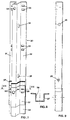
- a spacing element 10 which has the task of vertically spacing from each other two adjoining rows of horizontal boards.
- Said element consists of a U-shaped channel 11, on which pairs of pre-bent metal tongues 12 are welded at regular intervals, said tongues being made, in the example under examination, of harmonic steel, so as to insure a certain degree of flexibility and elasticity.
- each tongue 12 there is a spacing element 13, also in the shape of a U-channel and being permanently fixed to the U-shaped channel 11.
- a slot suited to receive a wedge which, as will be seen hereafter, and as can be observed in Fig. 2, by acting on the surface of boards 1 and 2, causes said boards to be compressed between the wedge and tongue 12.
- each spacing element presents holes 16 with a distance of 500 mm between the centers of each pair of holes, beginning from the ends, where there is a semi-hole 17.
- braces connecting the panels which form the formwork go through the holes 16.
- each hole 16 of the spacing element is always in the middle between two connecting elements 13, which are always arranged in pairs at the same distance from each other, while in the terminal part of the spacing element ending with a semi-hole 17, there is, on the same side, a pair of elements 13, presenting the characteristic that the connecting element 13 being closer to the semi-hole 17 is placed at a distance from this one corresponding to half the distance between two connecting elements 13 forming a pair and being placed at the side of a whole hole 16.
- each spacing element is represented by two flat bars welded at an inclined position, indicated with 36 and 40, which are positioned inside the U-shaped channel forming the spacing element 10. Said flat bars are placed near the pair of connecting elements 13 being closer to the semi-hole 17, as can be observed in the Figs. 3 and 4. The purpose of these flat bars is that of serving as an anchoring element for the vice hooks, which engage themselves on said flat bars and which tightly hold two adjoining panels, as will be better described hereafter.
- element 20 is nothing but another spacing element 10 having welded to its bottom a tube-shaped section 3, which takes the place of the last wooden board, and this because of obvious reasons of resistance to wear and tear during subsequent on-site erections.
- Fig. 10 shows an example of the first phase of formation of a panel of the invention presenting the details described so far, that is,spacing section of type 10, basic sections of type 20 and wooden boards having different sizes.
- spacing elements of type 20 each measuring one meter in length, are placed side by side; in the next row, indicated with 5, there are three spacing elements of type 10, one being one meter in length, while the other two measure 1.5 meters.
- the spacing element measuring one meter is comprised between two spacing elements measuring 1.5 meters, and thus, in the rows indicated with 7 and 8, the arrangement and the measurements of the spacing elements change.
- the used boards, which are comprised between rows of spacing elements are also of the most varied sizes, as can be observed. For instance, in Fig. 10, board 1 is 2.5 meters long, while board 2 measures 3 meters. All this indicates that no bond is set by the composition method according to the invention, for the formation of the panel.
- the arrangement of the long and short aligned spacing elements can be made in any way, and so can the distribution of the boards, with the single warning, which, however, is not binding, but is an improvement on the formed panel, that two edges of boards mounted on opposite sides of the same spacing element are not resting on the same vertical straight line, and this to insure more stiffness in the structure.
- post 10 shown in the example is an omega-shaped section presenting on its supporting surfaces 31 and 32 pairs of slots 33, which receive the connecting elements 13.
- a hole 34 suited to the passage of the braces connecting the formwork panels facing each other and passing thorugh the holes 16 of the spacing elements.
- the holes 33, which receive the connecting elements 13 are arranged in relation to each row of spacing elements
- the holes 34 for the passage of the braces are arranged at a double distance, that is in relation with every other row of spacing elements.
- transversal holes 35 on the lateral walls which, as will be explained further on, are meant for the passage of braces, which are used especially for the junction of the various elements of the formwork and also for the application of service accessories.
- the cross-section of the lower part 37 of post 30 is larger in relation to the cross section 38, belonging to the remaining upper part, as can be observed in Fig. 8, so that two adjoining posts 30 and 39 can be joined one on top of the other, for a certain stretch, so that the holes 33 and 34 coincide, thereby creating a continuity through the connecting elements 13 which pass through the holes of both superimposed posts.
- each post consists of two posts of type 30, now indicated with 41 and 42, joined together. Said posts are connected with each other by means of wedge pair 15, each wedge being mounted on opposite sides of the post, only one of them being visible in Fig. 11. In fact, said wedges are inserted into the holes of the connecting elements 13 belonging to the spacing element 10. In essence, the connection between the wedges 15 and the connecting elements 13 insures a double effect, that is, the effect of uniting with each other the posts 41 and 42 and the effect of connecting also said posts with the spacing elements 10.
- the connecting elements 13 would be grouped by four units, as can also be seen in the assembly scheme of Fig. 10.
- the connecting elements 13, which are used for the junction with the post will be the two middle ones, each belonging to a different spacing element, which also insures the connection between the two elements 10 placed next to each other.
- the rigidity and the compactness of the panel are insured.
- the insertion of the wedges 15 causes all the tongues 12 of the spacing elements 10 to be under stress and to exert their pressure on the wooden boards, which are, therefore, compressed between the tongues and the supporting surfaces of the post.
- connection brace 23 is represented in the drawing of Fig. 11 for simplicity sake. It can be observed that said brace goes through the holes of the spacing elements 10 and exits through the holes 34 of the posts, where it is fastened by the nuts 24.
- the brace is protected by a plastic tube 25 which acts as a spacing element and also protects the brace from being held by the setting concrete after the casting, so that, after the setting of the concrete, the braces can be removed and the panels 21 and 22 can be recovered.
- the panels 21 and 22 represented in Fig. 11, can acquire any length and width, the dimensions being limited exclusively by the necessity of handling the panels, said handling depending on the overall dimensions and the weight.
- posts 30 are applied, which constitute the terminal ribs of the panel and fulfil the function of connecting two panels placed side by side and the accessories used in the formwork.
- connection being necessary for the formation of a formwork, no matter what its dimensions.
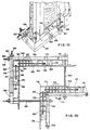
- the actions of putting two adjoining panels side by side, of aligning and tightening them are obtained by tightening the vices which engage themselves on flat bars welded at an inclined position inside the U-shaped channels of the spacing elements type 10.
- the vice indicated as a whole with 100, consists essentially of a shaped tube having a square or rectangular cross section 101, on a surface of which a hook 102 and a spacing pin 103 are welded.
- a through hole 104 In approximately the central position of tube 101 there is a through hole 104 and a reinforcement 105 consisting of a metal strip which sheathes tube 101 at the sides of the hole.
- the other element of the vice is tube 106 having a larger cross-section in relation to the first element, and being such that it can easily receive in its interior a part of tube 101.
- Both tube 101 and tube 106 have their terminal walls, indicated with 107 and 108 respectively, closed.
- Tube 106 is also provided with a hook 109 and with a spacing pin 110.
- a threaded tie rod 112 is welded on the end wall 107 of tube 101, while it goes through hole 114 drilled on the end wall of the other tube 106.
- vice 100 occurs when two panels are joined together in order to create one of the two front sides of the formwork. So, as can be observed in Fig. 13, the panels 116 and 117 are placed side by side before they are joined together.
- Said panels have their spacing elements equipped with flat bars welded at an inclined position, as can be observed in 125, 126, 127 and 128.
- vice 100 is positioned at the lower part of the two panels 116 and 117, and in Fig. 14 it can be seen how the hooks 102 and 109 of vice 100 engage themselves respectively on the inclined surfaces of the flat bars 126 and 128, belonging to the spacing element 119 of panel 116 and to the spacing element 129 of panel 117.
- one single vice 100 is not sufficient in order to obtain the side-by-side positioning and the alignment of the two panels 116 and 117. It is convenient to limit the use of the 100-type vices to the areas where one foresees the passage of the junction tie-rods between two panels facing each other, so that vice 100, being provided with a central hole, allows the passage and the stressing of brace 130, thereby performing also the function of an element reacting against the terminal posts 123 and 124 during the casting of the concrete.
- Fig. 15 represents the case where two neighboring panels must be spaced the one from the other by means of a compensation plate, in order to obtain a formwork having a length which differers from the length obtainable with the modular repetition of the panels. More precisely, and also with the help of Fig. 16, it can be observed that plate 133 is employed as a spacing element of the formwork to be obtained. In this case, the vice of the invention keeps its shape and function unaltered, with the difference that it presents two mobile parts 113, analogous to those already described with No. 106 in Fig. 12.
- vice 135 also engages itself on the flat inclined bars 134 and 136 belonging to the panels 131 and 132 respectively, but in the specific case, the tightening of the vice does not bring the two panels 131 and 132 in touch with each other, but it simply nears them to one another and aligns them.
- the two panels 131 and 132 will approach each other until their end posts go to rest against the locking nuts 137 and 138 placed on the threaded spacing element 139.
- the threaded spacing element 139 is only locked by the nuts 140 and 141 on the shaped section 142 belonging to the spacing plate 133, while the nuts 137 and 138 are placed at the desired distance, and the terminal nuts 143 and 144 are not inserted.
- Fig. 15 shows how, in this case also, brace 145 finds its seat in the middle hole of vice 135, which during the casting also acts as a reaction element for brace 145 against the terminal posts of the two panels placed at the sides of plate 133.
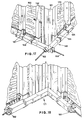
- the vice according to the invention which now is no longer straight but presents a right-angle shape and is, nonetheless, provided with the hooks peculiar to the vice, is suited to connect with each other the corner panels and to place them perpendicularly to one another.
- a box-shaped element such as, for instance, a tube with a square cross-section, exactly where the corner is going to be, and a series of compensating elements, also having a square or rectangular shape, placed between the box-shaped element and the panel to be connected.
- the number of compensating elements will be varied according to the desired thickness of the wall which one wants to obtain inside the formwork.
- the compensating elements are united with the box-shaped corner element by means of braces, which go through the transversal holes of the panel posts.
- Figs. 17 and 20 show the closing of the external corner obtained by means of vice 148.
- the corner panels 149 and 150 are directly in touch with each other, but they present, first of all, the box-shaped element 151 at their edge, and then a series of spacing elements 152.
- the box-shaped element 151 carries, welded in its interior, the nuts 153 and 154 into which the braces 155 and 156 are screwed. Through the locking of nut 157 on the post of panel 149, brace 155 brings panel 149 near the box-shaped element of corner 151.
- brace 156 unites the spacing elements 152 and brings panel 150 close to said compensating elements.
- the final locking and the perpendicularity between panel 149 and the compensating elements 152 and panel 150 is, however, guaranteed solely by the tightening of vice 148.
- brace 159 is welded on the mobile tube-shaped element 161 having a larger cross-section than the section of the arms 160 of the vice; said tube-shaped element 161 carries hook 162 and the spacing pin 170 and it slides on one of the arms 160 of the vice.
- brace 163 is welded on the mobile tube-shaped element 165, which carries hook 166 and the spacing pin 169; said element 165 slides on the other arm of the vice.
- the hooks 166 and 162 are stressed and they engage themselves leaning against the flat inclined bars 172 and 173 of the panels 149 and 150 respectively. In this way, the final tightening between the panels and the spacing elements, as well as the adjustment of the perpendicularity between panels 149 and 150 together with the spacing elements 152, is reached. It will be pointed out that in this case too, the spacing pins 169 and 170, placed near the hooks 166 and 162 respectively, insure the perpendicularity by acting as an arresting element during the tightning action performed by the hooks with the closing of the nuts 167 and 168 on the braces.
- the right-angle vice 172 functions as vice 148, with the difference that, in the case under examination, the tightening nuts of the braces inside the vice are placed at the ends of the arms of the vice itself and not at the edge, as in the case of the vice for the external corner.
- the formation of the inside corner of the formwork, in relation to the corner panels 174 and 175 is achieved equally by interposing the compensating elements 176 and 177 between the panels themselves and the corner box-shaped element 178.
- the braces 179 and 180 operate a first binding by tightening, while the final binding and the achievement of the perpendicularity is left to the tightening of vice 171 by tightening the nuts 181 and 182 on the braces 193 and 194 of the vice.
- braces on the side of the edge of the vice are screwed on the internal nuts being present in the compensating elements 117, adjoining the corner element 178.
- inside corner element 178 is exactly identical to and interchangeable with the outside corner element 151, in the same way as the elements 176 are identical to the compensating elements 152 and the elements 177 are interchangeable with said elements 152.
- braces 183 and 184 The junction between the inside corner and the outside one occurs by means of the connecting braces 183 and 184. Said braces pass from the outside to the inside through the second post of each panel counting from the edge and, viewed from the inside, beside the last compensating element. The locking nuts of these spacing braces 183 and 181 rest directly against the arms of the inside and outside vices, which, therefore, in this case too, act as reaction elements.
- Another special execution form of the vice being the object of the invention is used for the closing of the terminal end of the casting formwork.
- a board or a plate for the restraint of the concrete at the end of the casting space is placed between the two walls constituted by the panels.
- This board must be held vertically by means of rafters which lean against the board itself.
- Fig. 19 the metal bar 185 which acts as a rafter, is connected to vice 186 by means of a clamp 187 which allows the length adjustment.
- the threaded brace 188 is fixed inside vice 186, so that the sliding part 189 of the vice, which also carries hook 191 and the spacing pin 195, can go to contrast against nut 191 which, when screwed, stresses the vice and, as a consequence, pushes the rafter 185 against the board restraining the casting.
- hook 190 goes to lean against the flat bar 192 being present on the spacing element of the last panel of the formwork and the spacing pin 195 guarantees the rigidity of the system.
- the boards can be connected with the spacing elements not only by means of the tongues 12, but also by means of protrusions being present on the horizontal ribs of said elements, where said protrusions can acquire the shape of pointed projections penetrating the boards, or of aligned segments which penetrate into the central groove being foreseen on the rib of each board.
- the spacing element can be made with two shaped sections, one placed inside the other, both being rigidly connected with each other by means of a permanent deformation.
- the first shaped section presents a U-shape and it is formed in such a way as to form with its structure, the connecting elements 113 as well.
- Another U-shaped section presents some slots in its vertical part, which can receive the terminal ends of the tongues 12, shaped accordingly.
- This construction presents the obvious advantage that the spacing element is made without welding and it can, therefore, be moulded and assembled relatively easily and at a lower cost.
Landscapes
- Engineering & Computer Science (AREA)
- Architecture (AREA)
- Mechanical Engineering (AREA)
- Civil Engineering (AREA)
- Structural Engineering (AREA)
- Forms Removed On Construction Sites Or Auxiliary Members Thereof (AREA)
Claims (14)
Priority Applications (1)
| Application Number | Priority Date | Filing Date | Title |
|---|---|---|---|
| AT87102302T ATE64431T1 (de) | 1986-02-21 | 1987-02-18 | Verfahren fuer das zusammensetzen von paneelen zum errichten von schalungen an ort und stelle. |
Applications Claiming Priority (4)
| Application Number | Priority Date | Filing Date | Title |
|---|---|---|---|
| IT85515/86A IT1191594B (it) | 1986-02-21 | 1986-02-21 | Metodo di composizione di pannelli per la costruzione in opera di casseforme |
| IT8551586 | 1986-02-21 | ||
| IT8562586 | 1986-10-30 | ||
| IT8685625A IT1216439B (it) | 1986-10-30 | 1986-10-30 | Perfezionamenti al metodo di composizione di pannelli per la costruzione in opera di casseforme |
Publications (3)
| Publication Number | Publication Date |
|---|---|
| EP0233643A2 EP0233643A2 (de) | 1987-08-26 |
| EP0233643A3 EP0233643A3 (en) | 1988-08-31 |
| EP0233643B1 true EP0233643B1 (de) | 1991-06-12 |
Family
ID=26330153
Family Applications (1)
| Application Number | Title | Priority Date | Filing Date |
|---|---|---|---|
| EP19870102302 Expired EP0233643B1 (de) | 1986-02-21 | 1987-02-18 | Verfahren für das Zusammensetzen von Paneelen zum Errichten von Schalungen an Ort und Stelle |
Country Status (4)
| Country | Link |
|---|---|
| EP (1) | EP0233643B1 (de) |
| DE (1) | DE3770653D1 (de) |
| ES (1) | ES2025564T3 (de) |
| YU (1) | YU46188B (de) |
Cited By (1)
| Publication number | Priority date | Publication date | Assignee | Title |
|---|---|---|---|---|
| CN107476571A (zh) * | 2017-08-11 | 2017-12-15 | 中国化学工程第六建设有限公司 | 免打孔竹胶模板的施工方法 |
Families Citing this family (9)
| Publication number | Priority date | Publication date | Assignee | Title |
|---|---|---|---|---|
| US4957272A (en) * | 1989-06-23 | 1990-09-18 | Lee Yuan Ho | Modular concrete form |
| GB2314579A (en) * | 1996-06-24 | 1998-01-07 | Hsieh Ming Huei | Formwork |
| IT1315800B1 (it) * | 2000-01-14 | 2003-03-26 | Gaetano Vasques | Metodo per l'assemblaggio di una cassaforma modulare e cassaformamodulare cosi' ottenuta |
| US7210664B2 (en) * | 2004-08-06 | 2007-05-01 | Wilian Holding Company | Concrete form having adjustable curvature |
| ITAT20100001A1 (it) * | 2010-03-03 | 2011-09-04 | Roberto Murlo | Profili angolo veloce |
| ITVI20100233A1 (it) * | 2010-08-11 | 2012-02-12 | Legnotre Ind Spa | Sistema modulare per la composizione di un pannello per casseforme |
| EP3280851A4 (de) * | 2015-04-09 | 2018-10-03 | S.G.L Gavish Yizum U'vniya, Ltd. | Vorrichtung und verfahren zur konstruktion von härtbaren materialstrukturen |
| DE102016002360A1 (de) * | 2016-02-29 | 2017-08-31 | Redima Ag | Eckverbindungsvorrichtung einer Betonwandschalung |
| CN107700836A (zh) * | 2017-09-26 | 2018-02-16 | 福建建工集团有限责任公司 | 一种l形填充墙构造柱模板的加固体系及施工方法 |
Family Cites Families (3)
| Publication number | Priority date | Publication date | Assignee | Title |
|---|---|---|---|---|
| FR484403A (fr) * | 1917-02-05 | 1917-10-03 | Hydraulic Pressed Steel C | Perfectionnements aux coffrages et chassis de moulage |
| GB486797A (en) * | 1936-12-17 | 1938-06-10 | Robert Edwin Mcalpine | Improvements in shuttering means for the construction of concrete walls |
| GB539818A (en) * | 1940-02-23 | 1941-09-25 | Leonard Marshall Pascoe | Improvements in metal shuttering for casting concrete walls and the like |
-
1987
- 1987-02-18 EP EP19870102302 patent/EP0233643B1/de not_active Expired
- 1987-02-18 ES ES87102302T patent/ES2025564T3/es not_active Expired - Lifetime
- 1987-02-18 DE DE8787102302T patent/DE3770653D1/de not_active Expired - Fee Related
- 1987-02-20 YU YU25387A patent/YU46188B/sh unknown
Cited By (1)
| Publication number | Priority date | Publication date | Assignee | Title |
|---|---|---|---|---|
| CN107476571A (zh) * | 2017-08-11 | 2017-12-15 | 中国化学工程第六建设有限公司 | 免打孔竹胶模板的施工方法 |
Also Published As
| Publication number | Publication date |
|---|---|
| YU46188B (sh) | 1993-05-28 |
| ES2025564T3 (es) | 1992-04-01 |
| YU25387A (en) | 1989-06-30 |
| EP0233643A2 (de) | 1987-08-26 |
| EP0233643A3 (en) | 1988-08-31 |
| DE3770653D1 (de) | 1991-07-18 |
Similar Documents
| Publication | Publication Date | Title |
|---|---|---|
| US6865859B2 (en) | Conversion corner chamfer for form work | |
| US6733059B2 (en) | Outside conversion corner for form work | |
| EP0233643B1 (de) | Verfahren für das Zusammensetzen von Paneelen zum Errichten von Schalungen an Ort und Stelle | |
| US3288427A (en) | Assemblable formwork for reinforced concrete structures | |
| US20170292280A1 (en) | Method for erecting a shuttering framework | |
| US4133155A (en) | Joist structure | |
| US20060179787A1 (en) | Formwork systems | |
| US2442292A (en) | Form for plastic structural work | |
| HUT70904A (en) | Form panel to building units of structural engineering | |
| US3211413A (en) | Concrete forms and components thereof | |
| US3648962A (en) | Concrete form work clamp | |
| US2396174A (en) | Form for the construction of concrete walls, beams, and the like | |
| JPH0941666A (ja) | コンクリート型枠工法 | |
| HU198767B (en) | Method for assembling the frame of framed high constructions and template framing for carrying out the method | |
| US3808761A (en) | Modular building construction | |
| US20110232218A1 (en) | Form work, system, and method | |
| MX2007011613A (es) | Panel para encofrado de muros y pilares. | |
| US1143047A (en) | Portable building. | |
| US3241802A (en) | Building form for concrete walls | |
| KR102827166B1 (ko) | 벽체 증타용 거푸집 시스템 | |
| US2802242A (en) | Bleacher seating structure | |
| CA1172229A (en) | Skid for heavy machinery and method for constructing same | |
| JP3124752B2 (ja) | 木造軸組の補強構造 | |
| AU2002323707B2 (en) | Formwork Systems | |
| DE805929C (de) | Verschalung fuer die Herstellung von Waenden, Balken oder sonstigen Bauteilen aus Beton o. dgl. |
Legal Events
| Date | Code | Title | Description |
|---|---|---|---|
| PUAI | Public reference made under article 153(3) epc to a published international application that has entered the european phase |
Free format text: ORIGINAL CODE: 0009012 |
|
| AK | Designated contracting states |
Kind code of ref document: A2 Designated state(s): AT CH DE ES FR IT LI |
|
| PUAL | Search report despatched |
Free format text: ORIGINAL CODE: 0009013 |
|
| AK | Designated contracting states |
Kind code of ref document: A3 Designated state(s): AT CH DE ES FR IT LI |
|
| 17P | Request for examination filed |
Effective date: 19881012 |
|
| 17Q | First examination report despatched |
Effective date: 19890926 |
|
| GRAA | (expected) grant |
Free format text: ORIGINAL CODE: 0009210 |
|
| AK | Designated contracting states |
Kind code of ref document: B1 Designated state(s): AT CH DE ES FR IT LI |
|
| REF | Corresponds to: |
Ref document number: 64431 Country of ref document: AT Date of ref document: 19910615 Kind code of ref document: T |
|
| ITF | It: translation for a ep patent filed | ||
| REF | Corresponds to: |
Ref document number: 3770653 Country of ref document: DE Date of ref document: 19910718 |
|
| EN | Fr: translation not filed | ||
| PG25 | Lapsed in a contracting state [announced via postgrant information from national office to epo] |
Ref country code: FR Effective date: 19911031 |
|
| PLBE | No opposition filed within time limit |
Free format text: ORIGINAL CODE: 0009261 |
|
| STAA | Information on the status of an ep patent application or granted ep patent |
Free format text: STATUS: NO OPPOSITION FILED WITHIN TIME LIMIT |
|
| 26N | No opposition filed | ||
| REG | Reference to a national code |
Ref country code: FR Ref legal event code: ST |
|
| PGFP | Annual fee paid to national office [announced via postgrant information from national office to epo] |
Ref country code: DE Payment date: 19930430 Year of fee payment: 7 |
|
| REG | Reference to a national code |
Ref country code: ES Ref legal event code: PC2A Owner name: LEGNOTRE, S.P.A. |
|
| PG25 | Lapsed in a contracting state [announced via postgrant information from national office to epo] |
Ref country code: DE Effective date: 19941101 |
|
| PGFP | Annual fee paid to national office [announced via postgrant information from national office to epo] |
Ref country code: AT Payment date: 19950131 Year of fee payment: 9 |
|
| PGFP | Annual fee paid to national office [announced via postgrant information from national office to epo] |
Ref country code: CH Payment date: 19950223 Year of fee payment: 9 |
|
| PG25 | Lapsed in a contracting state [announced via postgrant information from national office to epo] |
Ref country code: AT Effective date: 19960218 |
|
| PG25 | Lapsed in a contracting state [announced via postgrant information from national office to epo] |
Ref country code: LI Free format text: LAPSE BECAUSE OF NON-PAYMENT OF DUE FEES Effective date: 19960228 Ref country code: CH Free format text: LAPSE BECAUSE OF NON-PAYMENT OF DUE FEES Effective date: 19960228 |
|
| REG | Reference to a national code |
Ref country code: CH Ref legal event code: PL |
|
| PGFP | Annual fee paid to national office [announced via postgrant information from national office to epo] |
Ref country code: ES Payment date: 20010124 Year of fee payment: 15 |
|
| PG25 | Lapsed in a contracting state [announced via postgrant information from national office to epo] |
Ref country code: ES Free format text: LAPSE BECAUSE OF NON-PAYMENT OF DUE FEES Effective date: 20020219 |
|
| REG | Reference to a national code |
Ref country code: ES Ref legal event code: FD2A Effective date: 20031122 |
|
| PG25 | Lapsed in a contracting state [announced via postgrant information from national office to epo] |
Ref country code: IT Free format text: LAPSE BECAUSE OF NON-PAYMENT OF DUE FEES;WARNING: LAPSES OF ITALIAN PATENTS WITH EFFECTIVE DATE BEFORE 2007 MAY HAVE OCCURRED AT ANY TIME BEFORE 2007. THE CORRECT EFFECTIVE DATE MAY BE DIFFERENT FROM THE ONE RECORDED. Effective date: 20050218 |