EP0233505B1 - Agencement de châssis de préférence pour un véhicule léger à caisse autoportante - Google Patents
Agencement de châssis de préférence pour un véhicule léger à caisse autoportante Download PDFInfo
- Publication number
- EP0233505B1 EP0233505B1 EP87100904A EP87100904A EP0233505B1 EP 0233505 B1 EP0233505 B1 EP 0233505B1 EP 87100904 A EP87100904 A EP 87100904A EP 87100904 A EP87100904 A EP 87100904A EP 0233505 B1 EP0233505 B1 EP 0233505B1
- Authority
- EP
- European Patent Office
- Prior art keywords
- longitudinal
- frame
- cross
- longitudinal members
- frame arrangement
- Prior art date
- Legal status (The legal status is an assumption and is not a legal conclusion. Google has not performed a legal analysis and makes no representation as to the accuracy of the status listed.)
- Expired - Lifetime
Links
- 239000000725 suspension Substances 0.000 claims description 9
- 238000000429 assembly Methods 0.000 claims description 3
- 230000007704 transition Effects 0.000 claims 1
- 238000004519 manufacturing process Methods 0.000 description 4
- 239000000463 material Substances 0.000 description 3
- 230000000712 assembly Effects 0.000 description 2
- 230000005540 biological transmission Effects 0.000 description 2
- 238000010276 construction Methods 0.000 description 2
- 238000010521 absorption reaction Methods 0.000 description 1
- 230000002411 adverse Effects 0.000 description 1
- 238000005452 bending Methods 0.000 description 1
- 239000002131 composite material Substances 0.000 description 1
- 238000010586 diagram Methods 0.000 description 1
- 238000005516 engineering process Methods 0.000 description 1
- 230000002349 favourable effect Effects 0.000 description 1
- JEIPFZHSYJVQDO-UHFFFAOYSA-N iron(III) oxide Inorganic materials O=[Fe]O[Fe]=O JEIPFZHSYJVQDO-UHFFFAOYSA-N 0.000 description 1
- 239000002184 metal Substances 0.000 description 1
- 238000000034 method Methods 0.000 description 1
- 230000008092 positive effect Effects 0.000 description 1
- 230000003068 static effect Effects 0.000 description 1
Images

Classifications
-
- B—PERFORMING OPERATIONS; TRANSPORTING
- B62—LAND VEHICLES FOR TRAVELLING OTHERWISE THAN ON RAILS
- B62D—MOTOR VEHICLES; TRAILERS
- B62D21/00—Understructures, i.e. chassis frame on which a vehicle body may be mounted
- B62D21/15—Understructures, i.e. chassis frame on which a vehicle body may be mounted having impact absorbing means, e.g. a frame designed to permanently or temporarily change shape or dimension upon impact with another body
Definitions
- the invention relates to a frame arrangement of a passenger car, which is preferably provided with a self-supporting body, according to the preamble of patent claim 1.
- a generic frame arrangement is already known from AT-B-1 80 488.
- DE-B-10 04 496 shows a similarly constructed frame arrangement.
- a front frame which is separate from the actual vehicle frame or from the self-supporting body, on which, for example, the drive unit consisting of the engine and transmission can be arranged together with the front wheel suspension.
- This front frame which is provided with the drive unit and other units, can be attached to the self-supporting car body in a very simple manner along the main passenger car production line.
- the construction initially offers the advantage that it is possible in this way to manufacture motor vehicles using a relatively short main production line, whereas this construction method is disadvantageous in that the motor vehicles designed in this way do not optimally meet the safety requirements.
- the connecting bolts connecting the front frame to the self-supporting body can be sheared off by large transverse forces acting on them.
- the crumple zone which is already very unfavorable, would not be fully effective.
- Due to the rigid connection of the two side members through the front cross member a rigid system has been created where flexibility and deformability are more important. As a result, both longitudinal members are inevitably affected and, since each longitudinal member also serves as the wheel suspension, the axle geometry is permanently influenced.
- DE-C-10 04 496 also has the disadvantage that the selected position of the respective wheel suspension is disadvantageous. If transverse forces occur, they are introduced extremely unfavorably, namely in the middle, onto the longitudinal beam just affected, which then, acting as a bending beam, has to absorb the entire load. Among other things, this can adversely affect driving behavior.
- DE-A-28 45 548 which is also to be mentioned, shows a very complex one-piece support structure which extends between the bumper and passenger compartment and which, as shown in particular in FIG. 3 in this document, deforms overall. This makes the repair work that may still have to be carried out after a head-on collision extremely cost-intensive. The splitting of the forces occurring in a crash does not appear to be optimally solved.
- FIG. 1 shows a left longitudinal frame 1 and a part of a cross frame 3 connecting it to a corresponding right longitudinal frame 2 (FIG. 2).
- the frame parts 1 - 3 form part of the floor assembly of a self-supporting car body of a passenger car.
- a longitudinal beam 4, 5 is fastened to each of the two longitudinal frames 1, 2 by means of two connecting bolts 6, 7 in the direction of travel 8, at a front, somewhat higher connection point and at a rear, lower lying connection point.
- Both side members 4, 5 are connected to one another via a cross member 9 engaging in the region of the front connecting bolt 6. This connection can e.g. B.
- the screw connection has the advantage that just in a partially laterally acting collision, for example, only one of the side members 4, 5 can be exchanged in a simple manner, without doing so in the axis geometry of the other Side would have to be intervened.
- Each side member 4, 5 has parallel and offset front and rear parts 10, 11, 19, 20 as viewed in the direction of travel 8, the rear part 11, 20 also viewed in the direction of travel 8, a section 12, 21 extending obliquely upwards having. Because of the inclination of this section 12, 21 and the longitudinal axes of the two connecting bolts 6, 7 extend at an angle to each other so that when tightening the connecting bolts 6, 7 there is a rigid connection between the longitudinal frame 1, 2 of the floor assembly and the longitudinal beams 4, 5 of the Frame arrangement results.
- the front frame formed from side members 4, 5 and cross member 9 can thus be easily assembled as a complete assembly together with the units carried by it.
- each longitudinal beam 4, 5 on the inside of the inclined section 12, 21 in addition to the through hole 17 of the connecting bolt 6 has a truncated pyramid-shaped shoulder 13, for example protrudes into a corresponding, also truncated pyramid-shaped recess 14 of the respective longitudinal frame 1, 2.
- each longitudinal frame 1, 2 also has a shoulder 15, against which the end face 37 of the rear part 11, 20 of each longitudinal beam 4, 5 comes to bear.
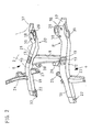
- the frame arrangement according to the invention is shown in perspective as a separate assembly.
- the H-shape formed from the two side members 4, 5 and the cross member 9 can be seen.
- One of the longitudinal frames 2 is also indicated.
- the truncated pyramid-shaped projection 13 with the through hole 17 for the connecting bolt 6 is also particularly clearly recognizable.
- the through hole 18 for the respective rear connecting bolt 7 is also shown.
- Both the longitudinal beams 4, 5 and the cross beam 9 are manufactured as pressed sheet metal parts, and a different choice of material for the components can optionally be made without any problems. This can arise, in particular, for reasons of strength, depending on which forces can act on the individual components in the event of a collision or which degree of deformation is desired. Among other things, it must also be taken into account which static and dynamic loads result from the assemblies, in particular the engine and transmission, which are attached to or supported by the front frame.
- the cross member 9 is welded to the two longitudinal members 4, 5, and, as already mentioned, a screw connection can also be readily provided.
- the components 9, 10, 11, 19, 20 which form the H shape furthermore have bores 22, 30, 31 for fastening or for the passage of various components, as well as webs 23, 24 and retaining brackets 25-29 for accommodating further assemblies, in particular motors and gearbox, inside the engine compartment.
- a towing hook 32 is fastened to at least one of the longitudinal beams 5 on its front part 19, and a bumper 33 of the motor vehicle can also be fastened to the two end faces of the front parts 19. This does not serve as an additional strength connection between the two longitudinal beams 4, 5, d. H. it does not transmit any significant transverse forces.
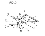
- Fig. 3 shows to illustrate the course of forces in a collision, the frame arrangement or its schematic representation as bars of a framework.
- rod forces of different magnitude force arrows F x
- the two front parts 10, 19 of the longitudinal beams 4, 5 essentially determine the crumple zone and will therefore also suffer a corresponding deformation.
- Each front part 10, 19 opens into a node 34, 35, which is formed in each case from the inclined section 12, 21 of the rear longitudinal member part 11, 20, the longitudinal frame 1, 2 acting thereon, and the cross member 9, and is extremely forms a rigid system that safely absorbs the forces and moments that occur.
- the node 34, 35 also determines the start of the safety zone for the vehicle occupants.
- the frame arrangement With the frame arrangement according to the invention, there is thus a possibility of being able to achieve a defined splitting of the forces occurring in the event of a collision, with an exact delimitation between a crumple zone absorbing the kinetic energy and a safety zone lying in front of the passenger compartment as seen in the direction of travel 8.
- the front wheel suspension By arranging the front wheel suspension in the area of the cross member 9, the frame arrangement also achieves optimum stability for the transverse forces resulting therefrom.
- Rust protection can also be taken into account when selecting materials.
Landscapes
- Engineering & Computer Science (AREA)
- Chemical & Material Sciences (AREA)
- Combustion & Propulsion (AREA)
- Transportation (AREA)
- Mechanical Engineering (AREA)
- Body Structure For Vehicles (AREA)
Claims (6)
Applications Claiming Priority (2)
| Application Number | Priority Date | Filing Date | Title |
|---|---|---|---|
| DE19863603706 DE3603706A1 (de) | 1986-02-06 | 1986-02-06 | Rahmenanordnung eines vorzugsweise mit einem selbsttragenden wagenkasten versehenen personenkraftwagens |
| DE3603706 | 1986-02-06 |
Publications (3)
| Publication Number | Publication Date |
|---|---|
| EP0233505A2 EP0233505A2 (fr) | 1987-08-26 |
| EP0233505A3 EP0233505A3 (en) | 1988-08-24 |
| EP0233505B1 true EP0233505B1 (fr) | 1990-05-23 |
Family
ID=6293550
Family Applications (1)
| Application Number | Title | Priority Date | Filing Date |
|---|---|---|---|
| EP87100904A Expired - Lifetime EP0233505B1 (fr) | 1986-02-06 | 1987-01-23 | Agencement de châssis de préférence pour un véhicule léger à caisse autoportante |
Country Status (5)
| Country | Link |
|---|---|
| US (1) | US4781398A (fr) |
| EP (1) | EP0233505B1 (fr) |
| JP (1) | JPS62194979A (fr) |
| DE (2) | DE3603706A1 (fr) |
| ES (1) | ES2015543B3 (fr) |
Cited By (2)
| Publication number | Priority date | Publication date | Assignee | Title |
|---|---|---|---|---|
| WO2005000664A1 (fr) * | 2003-06-30 | 2005-01-06 | Daimlerchrysler Ag | Avant-corps d'une automobile |
| DE102010053464A1 (de) * | 2010-12-03 | 2012-06-06 | GM Global Technology Operations LLC | Rahmenstruktur für ein Kraftfahrzeug, hintere Rahmenstruktur und Fahrzeugkarosserie |
Families Citing this family (23)
| Publication number | Priority date | Publication date | Assignee | Title |
|---|---|---|---|---|
| JPS6364883A (ja) * | 1986-09-04 | 1988-03-23 | Mazda Motor Corp | 自動車のフロントフレ−ム構造 |
| DE4029153C2 (de) * | 1989-09-21 | 1999-09-16 | Volkswagen Ag | Akustisch entkoppelte Bodengruppe für ein Kraftfahrzeug |
| DE3942794A1 (de) * | 1989-12-23 | 1991-07-04 | Bayerische Motoren Werke Ag | Rahmenanordnung fuer ein kraftfahrzeug |
| US5605353A (en) * | 1995-08-09 | 1997-02-25 | General Motors Corporation | Vehicle chassis with energy management |
| KR100284913B1 (ko) * | 1996-02-09 | 2001-03-15 | 와다 아끼히로 | 차체 전방부 구조 및 차체 전방부 구조에 의한 충격 흡수 방법 |
| US5884963A (en) * | 1996-09-23 | 1999-03-23 | Daimlerchrysler Corporation | Front suspension cross-member to torque box energy management and toe board intrusion limiter |
| US5951097A (en) * | 1997-04-17 | 1999-09-14 | Chrysler Corporation | Impact reinforcement for curved rails in motor vehicles |
| US6428046B1 (en) * | 1997-10-17 | 2002-08-06 | The Budd Company | Front cradle for a vehicle |
| DE69805388T2 (de) * | 1997-11-30 | 2002-11-14 | Isuzu Motors Ltd., Tokio/Tokyo | Ausbildung des vorderen Längsträgers eines Kraftfahrzeuges |
| US6007099A (en) * | 1997-12-01 | 1999-12-28 | Ford Global Technologies, Inc. | Vehicle intrusion energy management frame element |
| GB2334008A (en) | 1997-12-20 | 1999-08-11 | Rover Group | Vehicle subframes |
| DE19953382B4 (de) * | 1999-11-06 | 2006-01-05 | Audi Ag | Fahrzeugkarosserie mit einer Zelle und einem damit verbindbaren, vormontierbaren Vorbaumodul |
| US6367869B1 (en) * | 2000-07-26 | 2002-04-09 | Ford Global Technologies, Inc. | Energy management system and method for an extruded aluminum vehicle subframe |
| JP3606250B2 (ja) * | 2001-10-29 | 2005-01-05 | 日産自動車株式会社 | 車体前部構造 |
| US7243981B2 (en) * | 2005-06-03 | 2007-07-17 | Daimlerchrysler Corporation | Vehicle body deformation control assembly |
| DE102006028756B4 (de) * | 2006-06-20 | 2010-06-10 | Bayerische Motoren Werke Aktiengesellschaft | Kraftfahrzeug |
| US7695018B2 (en) * | 2007-08-27 | 2010-04-13 | Shoap Stephen D | Method and apparatus for a shared crumple zone |
| DE102008010553B4 (de) * | 2008-02-22 | 2023-07-20 | Dr. Ing. H.C. F. Porsche Aktiengesellschaft | Hilfsrahmen für eine Vorderachse eines Kraftfahrzeugs |
| US8113554B2 (en) * | 2008-10-30 | 2012-02-14 | Shoap Stephen D | Method and apparatus for an attachable and removable crumple zone |
| US9365241B1 (en) * | 2015-03-04 | 2016-06-14 | Honda Motor Co., Ltd. | Vehicle crash management apparatus and methods of use and manufacture thereof |
| JP6462785B1 (ja) * | 2017-07-13 | 2019-01-30 | 株式会社Subaru | 車体前部構造 |
| DE102018209115B4 (de) | 2018-06-08 | 2023-02-23 | Audi Ag | Hilfsrahmen für ein Kraftfahrzeug |
| RU190497U1 (ru) * | 2019-03-29 | 2019-07-02 | Николай Николаевич Тимошенко | Подвеска транспортного средства |
Family Cites Families (13)
| Publication number | Priority date | Publication date | Assignee | Title |
|---|---|---|---|---|
| US2074158A (en) * | 1933-07-10 | 1937-03-16 | Clarence W Avery | Vehicle construction |
| BE487370A (fr) * | 1948-04-07 | |||
| AT180488B (de) * | 1952-11-21 | 1954-12-10 | Fiat Spa | Vorderer Hilfsrahmen für Kraftfahrzeuge mit selbsttragender Karosserie |
| FR1093808A (fr) * | 1953-03-04 | 1955-05-10 | Fiat Spa | Châssis avant démontable pour véhicules automobiles à carrosserie monocoque |
| FR1436802A (fr) * | 1965-03-18 | 1966-04-29 | Citroen Sa Andre | Perfectionnements apportés aux châssis des véhicules automobiles |
| GB1451675A (en) * | 1973-06-12 | 1976-10-06 | Nissan Motor | Vehicle body construction |
| DE2408548C2 (de) * | 1974-02-22 | 1982-05-19 | Audi Nsu Auto Union Ag, 7107 Neckarsulm | Wagenkastenunterrahmen für Kraftfahrzeuge |
| US4046415A (en) * | 1976-04-08 | 1977-09-06 | General Motors Corporation | Body mount system for a motor vehicle |
| DE2845548A1 (de) * | 1978-10-19 | 1980-04-30 | Daimler Benz Ag | Fahrzeug, insbesondere pkw |
| SE432395B (sv) * | 1980-11-24 | 1984-04-02 | Saab Scania Ab | Frontparti i motorfordon |
| DE3223156A1 (de) * | 1982-06-22 | 1983-12-22 | Dr.Ing.H.C. F. Porsche Ag, 7000 Stuttgart | Aufbau fuer kraftfahrzeuge, insbesondere personenkraftwagen |
| DE3434452A1 (de) * | 1984-09-20 | 1986-03-20 | Dr.Ing.H.C. F. Porsche Ag, 7000 Stuttgart | Verstaerkungseinheit fuer einen laengstraeger |
| DE3528818A1 (de) * | 1985-08-10 | 1987-02-19 | Audi Ag | Rahmenanordnung |
-
1986
- 1986-02-06 DE DE19863603706 patent/DE3603706A1/de active Granted
-
1987
- 1987-01-23 DE DE8787100904T patent/DE3762830D1/de not_active Expired - Fee Related
- 1987-01-23 ES ES87100904T patent/ES2015543B3/es not_active Expired - Lifetime
- 1987-01-23 EP EP87100904A patent/EP0233505B1/fr not_active Expired - Lifetime
- 1987-02-05 JP JP62026176A patent/JPS62194979A/ja active Pending
- 1987-02-06 US US07/011,632 patent/US4781398A/en not_active Expired - Fee Related
Cited By (4)
| Publication number | Priority date | Publication date | Assignee | Title |
|---|---|---|---|---|
| WO2005000664A1 (fr) * | 2003-06-30 | 2005-01-06 | Daimlerchrysler Ag | Avant-corps d'une automobile |
| DE102010053464A1 (de) * | 2010-12-03 | 2012-06-06 | GM Global Technology Operations LLC | Rahmenstruktur für ein Kraftfahrzeug, hintere Rahmenstruktur und Fahrzeugkarosserie |
| US8636314B2 (en) | 2010-12-03 | 2014-01-28 | GM Global Technology Operations LLC | Frame structure for a motor vehicle, rear frame structure, and vehicle body |
| US9108679B2 (en) | 2010-12-03 | 2015-08-18 | GM Global Technology Operations LLC | Frame structure for a motor vehicle, rear frame structure, and vehicle body |
Also Published As
| Publication number | Publication date |
|---|---|
| DE3762830D1 (de) | 1990-06-28 |
| ES2015543B3 (es) | 1990-09-01 |
| DE3603706A1 (de) | 1987-08-13 |
| US4781398A (en) | 1988-11-01 |
| EP0233505A2 (fr) | 1987-08-26 |
| DE3603706C2 (fr) | 1990-07-19 |
| JPS62194979A (ja) | 1987-08-27 |
| EP0233505A3 (en) | 1988-08-24 |
Similar Documents
| Publication | Publication Date | Title |
|---|---|---|
| EP0233505B1 (fr) | Agencement de châssis de préférence pour un véhicule léger à caisse autoportante | |
| DE102004039592C5 (de) | Crashbox | |
| EP3668777B1 (fr) | Arrangement de longeron pour véhicule | |
| DE102007035483B4 (de) | Crasheinrichtung | |
| DE69104216T2 (de) | Bugteil für ein kraftfahrzeug. | |
| DE19611934C1 (de) | Frontmodul für Kraftfahrzeuge | |
| EP1199224A1 (fr) | Ensemble pare-chocs | |
| DE102004008740A1 (de) | Querträger für Stoßfängersysteme | |
| DE3718841C2 (fr) | ||
| EP2540575A2 (fr) | Agencement de pare-chocs pour un véhicule automobile | |
| EP1083098A2 (fr) | Amortisseur de choc pour véhicule | |
| DE19603954C2 (de) | Prallträger für ein Kraftfahrzeug | |
| DE102010041184A1 (de) | Karosseriestruktur für einen Frontbereich eines Fahrzeugs | |
| DE19853338B4 (de) | Anordnung mit einer Frontsäule für einen Karosserierahmen eines Kraftfahrzeugs | |
| DE102004050435A1 (de) | Stoßfängersystem für Kraftfahrzeug | |
| EP1623881A1 (fr) | Cashbox pour véhicules automobiles | |
| EP1008468B2 (fr) | Support d'attelage | |
| DE10358492A1 (de) | Crashelement in Form eines Hohlprofils | |
| EP1010605A2 (fr) | Structure avant d'une carrosserie auto-porteuse d'un véhicule | |
| DE69500374T2 (de) | Einrichtung zum Verzehren der Aufprallenergie für ein Fahrzeug | |
| WO2006032439A1 (fr) | Dispositif pare-chocs | |
| DE10121354A1 (de) | Vorderwagen für ein Kraftfahrzeug | |
| DE19735089A1 (de) | Querträger zur Halterung der Lenksäule eines Kraftfahrzeuges, insbesondere eines Personenkraftwagens | |
| WO2017076563A1 (fr) | Ensemble train roulant ainsi que traverse et montant pour un tel ensemble train roulant | |
| DE102015210293A1 (de) | Karosseriestruktur für ein zweispuriges Fahrzeug |
Legal Events
| Date | Code | Title | Description |
|---|---|---|---|
| PUAI | Public reference made under article 153(3) epc to a published international application that has entered the european phase |
Free format text: ORIGINAL CODE: 0009012 |
|
| 17P | Request for examination filed |
Effective date: 19870123 |
|
| AK | Designated contracting states |
Kind code of ref document: A2 Designated state(s): DE ES FR GB IT SE |
|
| PUAL | Search report despatched |
Free format text: ORIGINAL CODE: 0009013 |
|
| RHK1 | Main classification (correction) |
Ipc: B62D 21/02 |
|
| AK | Designated contracting states |
Kind code of ref document: A3 Designated state(s): DE ES FR GB IT SE |
|
| 17Q | First examination report despatched |
Effective date: 19890911 |
|
| ITF | It: translation for a ep patent filed | ||
| GRAA | (expected) grant |
Free format text: ORIGINAL CODE: 0009210 |
|
| AK | Designated contracting states |
Kind code of ref document: B1 Designated state(s): DE ES FR GB IT SE |
|
| GBT | Gb: translation of ep patent filed (gb section 77(6)(a)/1977) | ||
| REF | Corresponds to: |
Ref document number: 3762830 Country of ref document: DE Date of ref document: 19900628 |
|
| ET | Fr: translation filed | ||
| ITTA | It: last paid annual fee | ||
| PLBE | No opposition filed within time limit |
Free format text: ORIGINAL CODE: 0009261 |
|
| STAA | Information on the status of an ep patent application or granted ep patent |
Free format text: STATUS: NO OPPOSITION FILED WITHIN TIME LIMIT |
|
| 26N | No opposition filed | ||
| EAL | Se: european patent in force in sweden |
Ref document number: 87100904.9 |
|
| PGFP | Annual fee paid to national office [announced via postgrant information from national office to epo] |
Ref country code: GB Payment date: 19951221 Year of fee payment: 10 |
|
| PGFP | Annual fee paid to national office [announced via postgrant information from national office to epo] |
Ref country code: SE Payment date: 19960115 Year of fee payment: 10 |
|
| PGFP | Annual fee paid to national office [announced via postgrant information from national office to epo] |
Ref country code: FR Payment date: 19960116 Year of fee payment: 10 |
|
| PGFP | Annual fee paid to national office [announced via postgrant information from national office to epo] |
Ref country code: ES Payment date: 19960124 Year of fee payment: 10 |
|
| PG25 | Lapsed in a contracting state [announced via postgrant information from national office to epo] |
Ref country code: GB Effective date: 19970123 |
|
| PG25 | Lapsed in a contracting state [announced via postgrant information from national office to epo] |
Ref country code: SE Effective date: 19970124 Ref country code: ES Free format text: LAPSE BECAUSE OF NON-PAYMENT OF DUE FEES Effective date: 19970124 |
|
| GBPC | Gb: european patent ceased through non-payment of renewal fee |
Effective date: 19970123 |
|
| PG25 | Lapsed in a contracting state [announced via postgrant information from national office to epo] |
Ref country code: FR Effective date: 19970930 |
|
| EUG | Se: european patent has lapsed |
Ref document number: 87100904.9 |
|
| REG | Reference to a national code |
Ref country code: FR Ref legal event code: ST |
|
| PGFP | Annual fee paid to national office [announced via postgrant information from national office to epo] |
Ref country code: DE Payment date: 19971222 Year of fee payment: 12 |
|
| REG | Reference to a national code |
Ref country code: ES Ref legal event code: FD2A Effective date: 19990201 |
|
| PG25 | Lapsed in a contracting state [announced via postgrant information from national office to epo] |
Ref country code: DE Free format text: LAPSE BECAUSE OF NON-PAYMENT OF DUE FEES Effective date: 19991103 |
|
| PG25 | Lapsed in a contracting state [announced via postgrant information from national office to epo] |
Ref country code: IT Free format text: LAPSE BECAUSE OF NON-PAYMENT OF DUE FEES;WARNING: LAPSES OF ITALIAN PATENTS WITH EFFECTIVE DATE BEFORE 2007 MAY HAVE OCCURRED AT ANY TIME BEFORE 2007. THE CORRECT EFFECTIVE DATE MAY BE DIFFERENT FROM THE ONE RECORDED. Effective date: 20050123 |