EP0232943B1 - A method and an arrangement on packing machines - Google Patents
A method and an arrangement on packing machines Download PDFInfo
- Publication number
- EP0232943B1 EP0232943B1 EP87200176A EP87200176A EP0232943B1 EP 0232943 B1 EP0232943 B1 EP 0232943B1 EP 87200176 A EP87200176 A EP 87200176A EP 87200176 A EP87200176 A EP 87200176A EP 0232943 B1 EP0232943 B1 EP 0232943B1
- Authority
- EP
- European Patent Office
- Prior art keywords
- filling pipe
- accordance
- packing material
- packing
- connecting element
- Prior art date
- Legal status (The legal status is an assumption and is not a legal conclusion. Google has not performed a legal analysis and makes no representation as to the accuracy of the status listed.)
- Expired - Lifetime
Links
- 238000012856 packing Methods 0.000 title claims abstract description 110
- 238000000034 method Methods 0.000 title claims abstract description 38
- 239000000463 material Substances 0.000 claims abstract description 68
- 230000001954 sterilising effect Effects 0.000 claims abstract description 27
- 239000003206 sterilizing agent Substances 0.000 claims abstract description 25
- 238000004659 sterilization and disinfection Methods 0.000 claims abstract description 24
- MHAJPDPJQMAIIY-UHFFFAOYSA-N Hydrogen peroxide Chemical group OO MHAJPDPJQMAIIY-UHFFFAOYSA-N 0.000 claims description 4
- 238000004140 cleaning Methods 0.000 abstract description 18
- 238000004519 manufacturing process Methods 0.000 abstract description 12
- 239000012459 cleaning agent Substances 0.000 abstract description 7
- 238000007789 sealing Methods 0.000 description 12
- 208000035415 Reinfection Diseases 0.000 description 5
- 230000036512 infertility Effects 0.000 description 4
- 239000007788 liquid Substances 0.000 description 4
- XLYOFNOQVPJJNP-UHFFFAOYSA-N water Substances O XLYOFNOQVPJJNP-UHFFFAOYSA-N 0.000 description 4
- 239000002245 particle Substances 0.000 description 3
- 239000004033 plastic Substances 0.000 description 3
- 229920003023 plastic Polymers 0.000 description 3
- 238000012414 sterilization procedure Methods 0.000 description 3
- 235000013399 edible fruits Nutrition 0.000 description 2
- 230000033001 locomotion Effects 0.000 description 2
- 239000000123 paper Substances 0.000 description 2
- 230000000717 retained effect Effects 0.000 description 2
- 241000894006 Bacteria Species 0.000 description 1
- 239000005030 aluminium foil Substances 0.000 description 1
- 230000015572 biosynthetic process Effects 0.000 description 1
- 238000006243 chemical reaction Methods 0.000 description 1
- 239000003795 chemical substances by application Substances 0.000 description 1
- 230000007797 corrosion Effects 0.000 description 1
- 238000005260 corrosion Methods 0.000 description 1
- 238000005520 cutting process Methods 0.000 description 1
- 230000000694 effects Effects 0.000 description 1
- 239000012530 fluid Substances 0.000 description 1
- 239000007789 gas Substances 0.000 description 1
- 238000010438 heat treatment Methods 0.000 description 1
- 238000005304 joining Methods 0.000 description 1
- 235000013372 meat Nutrition 0.000 description 1
- 230000000149 penetrating effect Effects 0.000 description 1
- 230000000284 resting effect Effects 0.000 description 1
- 230000033764 rhythmic process Effects 0.000 description 1
- 229910001220 stainless steel Inorganic materials 0.000 description 1
- 239000010935 stainless steel Substances 0.000 description 1
- 230000007704 transition Effects 0.000 description 1
Images


Classifications
-
- B—PERFORMING OPERATIONS; TRANSPORTING
- B65—CONVEYING; PACKING; STORING; HANDLING THIN OR FILAMENTARY MATERIAL
- B65B—MACHINES, APPARATUS OR DEVICES FOR, OR METHODS OF, PACKAGING ARTICLES OR MATERIALS; UNPACKING
- B65B55/00—Preserving, protecting or purifying packages or package contents in association with packaging
- B65B55/02—Sterilising, e.g. of complete packages
-
- B—PERFORMING OPERATIONS; TRANSPORTING
- B67—OPENING, CLOSING OR CLEANING BOTTLES, JARS OR SIMILAR CONTAINERS; LIQUID HANDLING
- B67C—CLEANING, FILLING WITH LIQUIDS OR SEMILIQUIDS, OR EMPTYING, OF BOTTLES, JARS, CANS, CASKS, BARRELS, OR SIMILAR CONTAINERS, NOT OTHERWISE PROVIDED FOR; FUNNELS
- B67C3/00—Bottling liquids or semiliquids; Filling jars or cans with liquids or semiliquids using bottling or like apparatus; Filling casks or barrels with liquids or semiliquids
- B67C3/001—Cleaning of filling devices
- B67C3/002—Cleaning of filling devices using cups or dummies to be placed under the filling heads
-
- B—PERFORMING OPERATIONS; TRANSPORTING
- B65—CONVEYING; PACKING; STORING; HANDLING THIN OR FILAMENTARY MATERIAL
- B65B—MACHINES, APPARATUS OR DEVICES FOR, OR METHODS OF, PACKAGING ARTICLES OR MATERIALS; UNPACKING
- B65B2210/00—Specific aspects of the packaging machine
- B65B2210/06—Sterilising or cleaning machinery or conduits
Definitions
- the present invention relates to a method by means of which on a packing machine of the type wherein packing material in fillable shape is filled with contents via filling pipe comprising two feed ducts, both of which deliver contents to be packaged, parts of the machine are sterilized.
- the invention also relates to an arrangement for the realization of the method in accordance with one or more of the preceding claims on a packing machine of the type which has a filling pipe comprising two feed ducts for delivery of contents to be packed. Such a method and arrangement are known per se.
- Packing machines which produce packing containers of the non-returnable type by converting a flexible web of packing material to a material tube, successively filling the tube with contents and sealing the same in repeated transverse sealing zones placed at uniform intervals are known (US patent specification 3 325 961).
- the contents are fed via one or more feed ducts which are in the form of a filling pipe extend substantially vertically downwards into the packing material tube and open at some distance from the bottom of the same, that is to say slightly above the place where the repeated transverse sealing of the downwards directed tube occurs.
- the feed ducts as well as the outside of the filling pipe come into contact with the contents, and it is therefore very important that it should be possible to cleanse and sterilize these parts in an effective manner before the machine is started and production commences (so- called presterilization).
- presterilization the adjacent, inner part of the packing material tube must be sterile and if this is the case this sterility must not be allowed to be disrupted. This means in practice that the lower part of the filling pipe surrounded by the packing material tube is not accessible for manual cleaning or sterilization from the outside.
- a further difficulty is caused by the fact that the strong cleaning and sterilizing agent which has to be used for removing residues of contents and for sterilizing the internal, inaccessible parts of the feed ducts must not come into contact with the packing material tube consisting of paper or plastics, since this may then be destroyed and commence to leak so that the sterility might be lost.
- the sterilizing agent moreover, is delivered to the feed ducts under high pressure which would immediately burst the tube if the sterilizing agent were to be allowed to flow into the same. Nonetheless, the inside of the packing material tube as well as the outside of the filling pipe have to be sterilized prior to the start of production, that is to say before the packing machine is started to produce aseptic packing containers filled with sterile contents.
- an arrangement of the type mentioned in the introduction has been given the characteristic that it comprises a connecting element (20) joined in a detachable manner to the lower end of the filling pipe (19) so as to connect the outlet ends of the feed ducts (11, 12) to each other and so as to interrupt the connection between said outlet ends and a packing material tube (8) surrounding the filling pipe (10).
- the method and the arrangement in accordance with the invention make it possible with the help of strong cleaning and sterilizing agents and high pressure to cleanse the interior of the feed ducts without the packing material surrounding the filling pipe coming into contact with the sterilizing agent.
- the invention makes it possible, moreover, to change to an external sterilization of the filling pipe and a simultaneous internal sterilization of the packing material tube without a risk of reinfection of previously cleaned and sterilized parts of the feed ducts.
- the sterilization procedure can be interrupted and a successive start of production can take place in an automated and labour-saving manner, the procedure as a whole providing very great safety and eliminating the risk of non-sterile packages being produced after the start of production.
- the method and the arrangement in accordance with the invention can be used in a number of different types of packing machines which convert packing material in the form of a web or sheets to packing containers filled with contents.
- the invention will be described in the following as constructed when it is used on a packing machine of known type, which is described in more detail in SE-PS 8 401 288-9, to which reference is made.
- the packing machine 1 is fed with weblike packing material 2 which is supplied to the machine in the form of a roll 3 which is suspended so that it can freely rotate in the lower, rear part of the machine.
- the packing material 2 too is of known type and may consist, for example, of a laminate which comprises layers of paper, plastics and aluminium foil.
- the packing laminate, web 2 is conducted up via a number of guide rollers 4 to the upper part of the machine where it passes over a deflection roller 5 to run subsequently substantially vertically downwards along the front part of the machine.
- the packing material web 2 is successively converted to tubular shape which is done in that the two longitudinal edges of the packing material are folded with the help of folding elements 6 and guide rollers 7 and successively brought close to each other as the material web 2 is displaced downwards through the machine. Finally the two longitudinal edges of the packing material web will somewhat overlap each other and with the help of heating and sealing devices 9 the plastic layer of the packing material is heated along the said edges to softening temperature whereupon the edges are pressed together and cooled so that a longitudinal, liquid-tight sealing joint is formed.
- the material web 2 has been converted to a packing material tube 8 whose lower end is liquid-tight and surrounds a filling pipe 10 which also extends vertically through the machine.
- the filling pipe 10 which is itself comprises a number of feed ducts 11, 12 for contents, extends together with a further feed pipe 13 for sterile air through the upper, open end of the packing material tube 8.
- the filling pipe 10 opens at some distance above the lower, closed end of the packing material tube 8 whilst the feed pipe 13 extends down through, and opens below, a seal 14 which is located in the packing material tube 8 and which seals the lower, closed end of the latter from the upper, open end.
- a seal 14 which is located in the packing material tube 8 and which seals the lower, closed end of the latter from the upper, open end.
- the lower end of the packing material tube 8 is converted successively to individual, closed packing containers 15 with the help of sealing jaws 16 in reciprocating motion and likewise movable forming flaps 17 connected with them.
- the sealing jaws 16 in pairs are placed on either side of the tube and press the same together at uniform intervals so that transverse, flattened zones are produced wherein the packing material is sealed together in liquid-tight manner with the help of the heat and pressure supplied.
- the forming flaps 17 also operate in pairs and impart a substantially rectangular cross-sectional shape to the packing material tube 8, whereupon a further transverse sealing and a cutting off performed in the sealing zone separates the part of the packing material tube 8 which has been formed to packing containers 15 and filled with contents from the remaining part of the tube.
- the substantially cushionlike packing containers 15 thus formed, after undergoing possible further forming work in order to impart to them a substantially parallelepipedic shape, are ready and can be removed from the machine with the help of a conveyor, not shown.
- Fig. 2 is shown the lower end of the filling pipe 10 in section.
- the two feed ducts 11, 12 are situated concentrically inside each other, the inner feed duct 12 being intended to supply contents in liquid form, whilst the outer, annular feed duct 11 is intended to supply contents which comprise particles of fibres, e.g. lumps of fruit or meat.
- a tubular valve body 18 which is vertically displaceable in the lower end of the inner feed duct 12 by means of a manoeuvring rod 19 extending vertically upwards whose upper end is connected to a driving device, e.g. a pneumatic cylinder (not shown).
- the tubular valve body 18 permits free passage of the liquid fluid via the inner feed duct 12 and out through the lower end of the latter via the valve body 18. However, when the valve body 18 is displaced downwards to its closed position it will block the annular opening of the outer feed duct 11 and the valve body 18 in this position prevents a flowing out of contents from the feed duct 11.
- a detachable connecting element 20 which is in the shape of a cap or a plug is present at the lower end of the filling pipe 10 which with the help of an O-ring 21 extending around the periphery rests against the outlet of the feed duct 11 and is retained in the same.
- the connecting element 20 rests with its lower surface against a cup-shaped safety device 22 which with the help of a bayonet joint 23 is joined to, and encloses, the lower end of the filling pipe 10.
- the connecting element 20 as well as the safety device 22, just as the filling pipe 10, are appropriately made of a durable and corrosion-resistant material, e.g. stainless steel.
- the packing machine When the packing machine is in operation and, in accordance with known principles, converts the packing material web 2 to wholly or partially filled packing containers 15, the contents are supplied via the two feed ducts 11,12. Through the inner duct 12 a more or less continuous flow of liquid contents is supplied which pass through the valve body 18 and discharge into the lower end of the packing material tube 8 irrespectively of the position of the valve body 18. Via the outer feed duct 11 thicker contents which, for example, may contain particles of fruit pulp, are supplied. These thicker contents are delivered in portions in that the valve body 18 is moved upwards and downwards in rhythm with the advance of the packing material tube 8 and the transverse sealing off of the packing containers 15.
- the contents can flow out freely via the feed duct 11 through the lower end of the filling pipe 10 during a limited time of the package formation.
- the flow of contents via the feed duct 11 is interrupted, however, in good time before such a seal is to take place in that the valve body 18 is displaced into a lower position (not shown) where its front end shuts off the outlet of the feed duct 11 and prevents further outflow of contents via the feed duct 11.
- the liquid contents though, in spite of this can flow unhindered down into the packing material tube.
- Fig. 3A is shown schematically the lower end of the filling pipe 10 and the surrounding packing material tube 8 in the position they assume when the production of packing containers has been completed.
- the packing material tube 8 surrounds the whole length of the filling pipe 10 and is sealed in a liquid-tight manner at its lower end.
- the end of the tube 8, that is to say the part of the tube located below the seal is empty and the two feed pipes 11, 12 too have been emptied of contents in connection with the stoppage of the machine.
- the lower, sealed part of the packing material tube 8 is first removed so that the lower end of the filling pipe 10 becomes accessible from the outside.
- the lower end of the filling pipe es now provided with the connecting element 20 which, as mentioned previously, is in the form of a plug or a cap which is inserted in the outlet of the feed duct 11 and is retained there in a sealing position with the help of an O-ring resting against the edge of the outlet.
- a pure friction engagement naturally can be made use of or else springloaded hooks or the like can be provided so as to retain the connecting element 20 securely at the lower end of the filling pipe 10.
- the connecting element 20 When the connecting element 20 is placed in position the lower end of the filling pipe 10 is provided with the cup-shaped safety device 22 which is connected mechanically by hand to the filling pipe 10 with the help of a bayonet joint 23.
- the safety device 22 When the safety device 22 has been applied its internal lower surface will come to rest against, and support, the connecting element 20 so that the latter sits immovably in the outlet of the feed duct 11 and in this position where it forms a complete seal, it can resist high internal pressures in the filling pipe 10 and thus prevent pressure damages on the packing material surrounding the filling pipe.
- a closed connection is provided between the two feed ducts 11, 12 at the lower end of the filling pipe 10, that is to say the outlet ends of the two feed ducts 11,12 will be connected to each other at the same time as they are screended off from the surrounding packing material tube and the outside of the filling pipe 10.
- the connecting element 20 a closed connection is provided between the two feed ducts 11, 12 at the lower end of the filling pipe 10, that is to say the outlet ends of the two feed ducts 11,12 will be connected to each other at the same time as they are screended off from the surrounding packing material tube and the outside of the filling pipe 10.
- the connecting element 20 is held in position with the help of the safety device 22 which is designed so as to withstand the high pressure which arises in the filling pipe in the course of the circulation of steam.
- the steam is produced in a steam generator connected to the packing machine and is conducted via the existing valves for the contents and the existing contents ducts to the lower end of the filling pipe 10.
- the steam circulation has proceeded for the required time it is interrupted and the feed ducts and the filling pipe 10 are cooled which can be done with the help of sterile condensed water or cold sterile air which is allowed to circulate for the required time in the filling pipe.
- Sterilizing agent flows through the said parts during the required time, whereupon the sterilization process is interrupted, the packing machine is started and the sterile contents are delivered via the two feed ducts 11, 12 in conventional manner.
- the cleaning and sterilizing process is thus completed and the packing machine can produce again aseptic packing containers which are wholly or partially filled with sterile contents.
- the connecting element may be, for example, in the form of a cup or a U-shaped pipe and in the case of filling pipes with a different number of feed ducts or different design it is also possible, while retaining the function, to construct the conect- ing element in a suitabe manner.
- the valve body 18 or the valve arrangement as a whole has been designed differently and it will be possible, whilst retaining the principle of the invention, to construct the connecting element in such a manner that it can be adapted to any known type of filling pipe.
- connecting element should be removable in spite of the packing material tube hindering direct accessibility, that is to say without manual intervention being required.
- the removal of the connecting element can be performed, as mentioned earlier, on account of the pressure difference on both sides of the connecting element, that is to say the increased pressure in the feed ducts, but is is also possible to remove the connecting element with the help of the valve body which is moved to such a position that it pushes the connecting element out of the filling pipe or with the help of some other mechanically acting device.
- the method in accordance with the invention can also be modified by making use of alternative flow paths.
- the flow paths indicated by arrows it is possible, for example, instead of the flow paths indicated by arrows to allow the cleaning or sterilizing agent to flow in opposite directions.
- the type of cleaning and sterilizing agent too can be varied. The main thing is only that agents which are harmful to the packing material do not come into contact with the same and that it is not subjected to harmful pressure differences.
Landscapes
- Engineering & Computer Science (AREA)
- Mechanical Engineering (AREA)
- Basic Packing Technique (AREA)
- Auxiliary Devices For And Details Of Packaging Control (AREA)
- Filling Of Jars Or Cans And Processes For Cleaning And Sealing Jars (AREA)
- Buffer Packaging (AREA)
- Containers And Plastic Fillers For Packaging (AREA)
Abstract
Description
- The present invention relates to a method by means of which on a packing machine of the type wherein packing material in fillable shape is filled with contents via filling pipe comprising two feed ducts, both of which deliver contents to be packaged, parts of the machine are sterilized. The invention also relates to an arrangement for the realization of the method in accordance with one or more of the preceding claims on a packing machine of the type which has a filling pipe comprising two feed ducts for delivery of contents to be packed. Such a method and arrangement are known per se.
- Packing machines which produce packing containers of the non-returnable type by converting a flexible web of packing material to a material tube, successively filling the tube with contents and sealing the same in repeated transverse sealing zones placed at uniform intervals are known (US patent specification 3 325 961). In this type of machine the contents are fed via one or more feed ducts which are in the form of a filling pipe extend substantially vertically downwards into the packing material tube and open at some distance from the bottom of the same, that is to say slightly above the place where the repeated transverse sealing of the downwards directed tube occurs. Thus the feed ducts as well as the outside of the filling pipe come into contact with the contents, and it is therefore very important that it should be possible to cleanse and sterilize these parts in an effective manner before the machine is started and production commences (so- called presterilization). At the same time the adjacent, inner part of the packing material tube must be sterile and if this is the case this sterility must not be allowed to be disrupted. This means in practice that the lower part of the filling pipe surrounded by the packing material tube is not accessible for manual cleaning or sterilization from the outside.
- A further difficulty is caused by the fact that the strong cleaning and sterilizing agent which has to be used for removing residues of contents and for sterilizing the internal, inaccessible parts of the feed ducts must not come into contact with the packing material tube consisting of paper or plastics, since this may then be destroyed and commence to leak so that the sterility might be lost. The sterilizing agent, moreover, is delivered to the feed ducts under high pressure which would immediately burst the tube if the sterilizing agent were to be allowed to flow into the same. Nonetheless, the inside of the packing material tube as well as the outside of the filling pipe have to be sterilized prior to the start of production, that is to say before the packing machine is started to produce aseptic packing containers filled with sterile contents.
- When a packing machine for example of the type described above is to be presterilized before the start of production, a sterilization process will have to be utilized, therefore, which involves a change from the sterilization of the feed ducts, the outside of the filling pipe and the inside of the packing material tube to a subsequent production situation without any disruption of the sterility achieved. It must be possible to carry out the transition from internal sterilization of the feed ducts to external sterilization of the filling pipe without the occurrence of a risk of reinfection of the feed ducts, that is to say without their inside being brought into contact with the environment.
- An earlier attempt to provide a cleaning and sterilization process on similar packing machines included dismantling of parts of the filling pipe for manual cleaning and sterilization, and it was not possible during the manual mounting of the filling pipe completely to avoid the risk of reinfection. Another earlier attempt to solve the problem involves the use of a special, supplementary pipe with valve means for feeding a sterilizing agent used for the cleaning and sterilization of the filling pipe (US-A 3 457 968).
- It is an object of the present invention to provide a method for the presterilization of the filling pipe and the feed ducts of a packing machine and possibly also of adjacent parts of the machine and packing material, this method not being subject to the disadvantages which were attached to previously known, corresponding sterilization procedures.
- It is a further object of the present invention to provide a cleaning and sterilization procedure which is especially applicable to packing machines of the type which comprises two feed ducts.
- It is a further object of the present invention to provide a sterilization process which can be carried out in a safe and effective manner and which appreciably reduces, or completely eliminates, the risk of reinfection and non-sterility.
- These and other objects have been achieved in accordance with the invention in that a method of the type mentioned in the introduction has been given the characteristic that the supply of filling contents to the feed ducts is stopped and a part of the packing material surrounding the lower end of the filling pipe is removed, so that the outlet ends of the feed ducts can be connected to each other and sterilized internally by means of a sterilizing agent which is fed through the ducts, whereafter the packing material is fed and sealed below the filling pipe outlet and the filling pipe is sterilized externally by means of a sterilizing agent which is introduced between the pipe and the surrounding packing material.
- Preferred embodiments of the method in accordance with the invention have been given the characteristics which are evident from
claims 2 to 10 inclusive. - It is an object of the present invention, moreover, to provide an arrangement which makes it possible to realize the method in accordance with the invention with the help of simple and low-cost devices which are simple to handle and ensure a satisfactory result.
- It is a further object of the present invention to provide an arrangement for the realization of the method, this arrangement comprising elements for joining together the outlet ends of the feed ducts and isolate the feed ducts from the environment, especially the surrounding packing material.
- These and other objects have been achieved in accordance with the invention in that an arrangement of the type mentioned in the introduction has been given the characteristic that it comprises a connecting element joined in a detachable manner to the lower end of the filling pipe which connects the outlet ends of the feed ducts to each other.
- These and other objects have been achieved in accordance with the invention in that an arrangement of the type mentioned in the introduction has been given the characteristic that it comprises a connecting element (20) joined in a detachable manner to the lower end of the filling pipe (19) so as to connect the outlet ends of the feed ducts (11, 12) to each other and so as to interrupt the connection between said outlet ends and a packing material tube (8) surrounding the filling pipe (10).
- Preferred embodiments of the arrangement in accordance with the invention have been given, moreover, the characteristics which are evident from subsidiary claims 12-15.
- The method and the arrangement in accordance with the invention make it possible with the help of strong cleaning and sterilizing agents and high pressure to cleanse the interior of the feed ducts without the packing material surrounding the filling pipe coming into contact with the sterilizing agent. The invention makes it possible, moreover, to change to an external sterilization of the filling pipe and a simultaneous internal sterilization of the packing material tube without a risk of reinfection of previously cleaned and sterilized parts of the feed ducts. Finally the sterilization procedure can be interrupted and a successive start of production can take place in an automated and labour-saving manner, the procedure as a whole providing very great safety and eliminating the risk of non-sterile packages being produced after the start of production.
- A preferred embodiment of the method as well as of the arrangement in accordance with the invention will now be described in greater detail with special reference to the enclosed schematic drawings which only show the details essential for an understanding of the invention.
- Fig. 1 shows in perspective and partially in section the principle, known in itself, of the conversion of a packing material web to tubular shape for the manufacture of filled packing containers.
- Fig. 2 shows in section the lower end of a filling pipe with the connecting element and safety device according to the invention fitted.
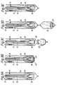
- Fig. 3 A-E shows the successive procedure for the performance of a presterilization in accordance with the method according to the invention.
- The method and the arrangement in accordance with the invention can be used in a number of different types of packing machines which convert packing material in the form of a web or sheets to packing containers filled with contents. However, for the sake of clearness the invention will be described in the following as constructed when it is used on a packing machine of known type, which is described in more detail in SE-
PS 8 401 288-9, to which reference is made. - The
packing machine 1 is fed withweblike packing material 2 which is supplied to the machine in the form of a roll 3 which is suspended so that it can freely rotate in the lower, rear part of the machine. Thepacking material 2 too is of known type and may consist, for example, of a laminate which comprises layers of paper, plastics and aluminium foil. The packing laminate,web 2 is conducted up via a number of guide rollers 4 to the upper part of the machine where it passes over adeflection roller 5 to run subsequently substantially vertically downwards along the front part of the machine. During its downwards movement through the machine thepacking material web 2 is successively converted to tubular shape which is done in that the two longitudinal edges of the packing material are folded with the help of foldingelements 6 andguide rollers 7 and successively brought close to each other as thematerial web 2 is displaced downwards through the machine. Finally the two longitudinal edges of the packing material web will somewhat overlap each other and with the help of heating and sealing devices 9 the plastic layer of the packing material is heated along the said edges to softening temperature whereupon the edges are pressed together and cooled so that a longitudinal, liquid-tight sealing joint is formed. Thus thematerial web 2 has been converted to apacking material tube 8 whose lower end is liquid-tight and surrounds afilling pipe 10 which also extends vertically through the machine. Thefilling pipe 10, which is itself comprises a number offeed ducts further feed pipe 13 for sterile air through the upper, open end of thepacking material tube 8. Thefilling pipe 10 opens at some distance above the lower, closed end of thepacking material tube 8 whilst thefeed pipe 13 extends down through, and opens below, aseal 14 which is located in thepacking material tube 8 and which seals the lower, closed end of the latter from the upper, open end. In the closed space so formed contents can be introduced into the tube under sterile conditions by means of thefilling pipe 10. The lower end of thepacking material tube 8 is converted successively to individual, closedpacking containers 15 with the help of sealingjaws 16 in reciprocating motion and likewise movable formingflaps 17 connected with them. The sealingjaws 16 in pairs are placed on either side of the tube and press the same together at uniform intervals so that transverse, flattened zones are produced wherein the packing material is sealed together in liquid-tight manner with the help of the heat and pressure supplied. The formingflaps 17 also operate in pairs and impart a substantially rectangular cross-sectional shape to thepacking material tube 8, whereupon a further transverse sealing and a cutting off performed in the sealing zone separates the part of thepacking material tube 8 which has been formed to packingcontainers 15 and filled with contents from the remaining part of the tube. The substantiallycushionlike packing containers 15 thus formed, after undergoing possible further forming work in order to impart to them a substantially parallelepipedic shape, are ready and can be removed from the machine with the help of a conveyor, not shown. - In Fig. 2 is shown the lower end of the
filling pipe 10 in section. The twofeed ducts inner feed duct 12 being intended to supply contents in liquid form, whilst the outer,annular feed duct 11 is intended to supply contents which comprise particles of fibres, e.g. lumps of fruit or meat. At the lower end of thefilling pipe 10 there is, moreover, atubular valve body 18 which is vertically displaceable in the lower end of theinner feed duct 12 by means of amanoeuvring rod 19 extending vertically upwards whose upper end is connected to a driving device, e.g. a pneumatic cylinder (not shown). Thetubular valve body 18 permits free passage of the liquid fluid via theinner feed duct 12 and out through the lower end of the latter via thevalve body 18. However, when thevalve body 18 is displaced downwards to its closed position it will block the annular opening of theouter feed duct 11 and thevalve body 18 in this position prevents a flowing out of contents from thefeed duct 11. - When the packing machine is to be presterilized with the help of the method and arrangement in accordance with the invention a detachable connecting
element 20 which is in the shape of a cap or a plug is present at the lower end of thefilling pipe 10 which with the help of an O-ring 21 extending around the periphery rests against the outlet of thefeed duct 11 and is retained in the same. The connectingelement 20 rests with its lower surface against a cup-shaped safety device 22 which with the help of abayonet joint 23 is joined to, and encloses, the lower end of thefilling pipe 10. When thesafety device 22 has been fitted manually with the help of the bayonet joint to the lower end of thefilling pipe 10 it will support the connectingelement 20 and prevent it from being removed from the outlet on thedelivery duct 11, e.g. owing to pressure effects from the interior of thefilling pipe 10. The connectingelement 20 as well as thesafety device 22, just as thefilling pipe 10, are appropriately made of a durable and corrosion-resistant material, e.g. stainless steel. - When the packing machine is in operation and, in accordance with known principles, converts the
packing material web 2 to wholly or partially filledpacking containers 15, the contents are supplied via the twofeed ducts valve body 18 and discharge into the lower end of thepacking material tube 8 irrespectively of the position of thevalve body 18. Via theouter feed duct 11 thicker contents which, for example, may contain particles of fruit pulp, are supplied. These thicker contents are delivered in portions in that thevalve body 18 is moved upwards and downwards in rhythm with the advance of the packingmaterial tube 8 and the transverse sealing off of thepacking containers 15. In the upper position of thevalve body 18 the contents can flow out freely via thefeed duct 11 through the lower end of thefilling pipe 10 during a limited time of the package formation. To ensure that contents in particle form do not get stuck in transverse seals of the tube, the flow of contents via thefeed duct 11 is interrupted, however, in good time before such a seal is to take place in that thevalve body 18 is displaced into a lower position (not shown) where its front end shuts off the outlet of thefeed duct 11 and prevents further outflow of contents via thefeed duct 11. The liquid contents, though, in spite of this can flow unhindered down into the packing material tube. - During production of packing containers the connecting
element 20 as well as thesafety device 22 are thus removed from the lower end of thefilling pipe 10. These two devices, 20, 22, are used only when the packing machine is to be cleaned and sterilized with the help of cleaning and sterilizing agents well-known in the trade, e.g. hot steam and hydrogen peroxide. The cleaning and sterilizing procedure in accordance with the invention will be described in more detail in the following with special reference to Fig. 3 which shows schematically the different phases of the process in Figures A-E. In Flg. 3 the fillingpipe 10 is shown in section and the packingmaterial tube 8 is indicated by means of dash-dotted lines. The reference designations correspond to those indicated in Figures 1 and 2. - In Fig. 3A is shown schematically the lower end of the filling
pipe 10 and the surrounding packingmaterial tube 8 in the position they assume when the production of packing containers has been completed. The packingmaterial tube 8 surrounds the whole length of the fillingpipe 10 and is sealed in a liquid-tight manner at its lower end. The end of thetube 8, that is to say the part of the tube located below the seal is empty and the twofeed pipes - When the packing machine is to be started again an accurate cleaning and sterilization of the inside of the filling pipe is required, that is to say of the two
feed ducts pipe 10 which can come into contact with the contents, that is to say the part located below theseal 14. The part of the packing material tube too which surrounds the fillingpipe 8 has to be sterilized in order to ensure aseptic conditions when the machine is to be restarted and is to commence producing aseptic packing containers for sterile contents. - To make possible an internal cleaning and sterilization of the two
feed ducts 11 the lower, sealed part of the packingmaterial tube 8 is first removed so that the lower end of the fillingpipe 10 becomes accessible from the outside. The lower end of the filling pipe es now provided with the connectingelement 20 which, as mentioned previously, is in the form of a plug or a cap which is inserted in the outlet of thefeed duct 11 and is retained there in a sealing position with the help of an O-ring resting against the edge of the outlet. A pure friction engagement naturally can be made use of or else springloaded hooks or the like can be provided so as to retain the connectingelement 20 securely at the lower end of the fillingpipe 10. When the connectingelement 20 is placed in position the lower end of the fillingpipe 10 is provided with the cup-shapedsafety device 22 which is connected mechanically by hand to the fillingpipe 10 with the help of a bayonet joint 23. When thesafety device 22 has been applied its internal lower surface will come to rest against, and support, the connectingelement 20 so that the latter sits immovably in the outlet of thefeed duct 11 and in this position where it forms a complete seal, it can resist high internal pressures in the fillingpipe 10 and thus prevent pressure damages on the packing material surrounding the filling pipe. - Through application of the connecting element 20 a closed connection is provided between the two
feed ducts pipe 10, that is to say the outlet ends of the twofeed ducts pipe 10. As a result it becomes possible to circulate cleaning as well as sterilizing agent through the twofeed ducts - For the internal sterilization of the filling
pipe 10 hot steam is used which after the application of the connectingelement 20 and thesafety device 22 is made to flow down through theinner feed duct 12, out through the open valve body so as to be conducted by the connectingelement 20 sideways and up through the coaxial, outer feed duct 11 (Fig.3B). This combined cleaning and sterilization is allowed to continue until any residues of contents have been flushed out and the fillingpipe 10 as a whole has been heated to such a temperature that all bacteria have been rendered innocuous. The steam is supplied under a pressure which is such that it is capable of penetrating also into the smallest recesses which are present in the filling pipe. During this the connectingelement 20 is held in position with the help of thesafety device 22 which is designed so as to withstand the high pressure which arises in the filling pipe in the course of the circulation of steam. The steam is produced in a steam generator connected to the packing machine and is conducted via the existing valves for the contents and the existing contents ducts to the lower end of the fillingpipe 10. When the steam circulation has proceeded for the required time it is interrupted and the feed ducts and the fillingpipe 10 are cooled which can be done with the help of sterile condensed water or cold sterile air which is allowed to circulate for the required time in the filling pipe. Subsequently the external, cup-shapedsafety device 22 is removed by hand and the packingmaterial tube 8 is pulled down and sealed with the help of sealingjaws 16 of the packing machine in a liquid-tight seal below the lower end of the filling pipe 10 (Fig. 3C). - When the lower end of the packing
material tube 8 has been closed the machine is started and allowed to manufacture a number of packages (10-15 off) without any supply of contents whilst condensed, sterilized water or sterile air is intoduced into the packing material tube via the twofeed ducts element 20 from the outlet of thepipe 10 so that it falls down and ends up in the first-producedpacking container 15 together with sterile air and a certain amount of condensed or sterilized water (Fig. 3D) - When the system has been emptied of condensed air or sterilized water and only sterile air is packed in the packing containers produced the machine is stopped again in such a position that the packing
material tube 8 is closed off by a transverse, liquid-tight seal. Subsequently a sterilizing agent in vapour or gas form is introduced into the lower end of the packing material tube via theinner feed duct 12 and thefeed pipe 13. The sterilizing agent can flow out again from the packing material tube via theopen valve 18 and theouter feed duct 11. In this situation a simultaneous sterilization of the twofeed ducts pipe 10, thevalve body 18 and of the internal parts of the lower part of the packingmaterial tube 8 isolated by means of theseal 14 takes place. Sterilizing agent flows through the said parts during the required time, whereupon the sterilization process is interrupted, the packing machine is started and the sterile contents are delivered via the twofeed ducts - The method and the arrangement in accordance with the invention can be modified in different ways to adapt them to various types of packing machines and above all to various types of filling pipes. In packing machines which comprise non-concentric filling pipes the connecting element may be, for example, in the form of a cup or a U-shaped pipe and in the case of filling pipes with a different number of feed ducts or different design it is also possible, while retaining the function, to construct the conect- ing element in a suitabe manner. This is also the case if, for example, the
valve body 18 or the valve arrangement as a whole has been designed differently and it will be possible, whilst retaining the principle of the invention, to construct the connecting element in such a manner that it can be adapted to any known type of filling pipe. The important point is only that the connecting element should be removable in spite of the packing material tube hindering direct accessibility, that is to say without manual intervention being required. The removal of the connecting element can be performed, as mentioned earlier, on account of the pressure difference on both sides of the connecting element, that is to say the increased pressure in the feed ducts, but is is also possible to remove the connecting element with the help of the valve body which is moved to such a position that it pushes the connecting element out of the filling pipe or with the help of some other mechanically acting device. - The method in accordance with the invention can also be modified by making use of alternative flow paths. In the Figures 3B and 3E it is possible, for example, instead of the flow paths indicated by arrows to allow the cleaning or sterilizing agent to flow in opposite directions. The type of cleaning and sterilizing agent too can be varied. The main thing is only that agents which are harmful to the packing material do not come into contact with the same and that it is not subjected to harmful pressure differences.
- Trials in practice have confirmed that the object of the invention is achieved through cleaning and sterilization in stages, where each stage successively leads up to a complete sterilization of the filling pipe as well as the packing material tube without the risk of reinfection between stages.
Claims (15)
Priority Applications (1)
| Application Number | Priority Date | Filing Date | Title |
|---|---|---|---|
| AT87200176T ATE57877T1 (en) | 1986-02-14 | 1987-02-05 | PROCESS AND DEVICE IN PACKAGING MACHINES. |
Applications Claiming Priority (2)
| Application Number | Priority Date | Filing Date | Title |
|---|---|---|---|
| IT1942186 | 1986-02-14 | ||
| IT19421/86A IT1188390B (en) | 1986-02-14 | 1986-02-14 | METHOD AND COMPLEX IN PACKAGING MACHINES |
Publications (2)
| Publication Number | Publication Date |
|---|---|
| EP0232943A1 EP0232943A1 (en) | 1987-08-19 |
| EP0232943B1 true EP0232943B1 (en) | 1990-10-31 |
Family
ID=11157726
Family Applications (1)
| Application Number | Title | Priority Date | Filing Date |
|---|---|---|---|
| EP87200176A Expired - Lifetime EP0232943B1 (en) | 1986-02-14 | 1987-02-05 | A method and an arrangement on packing machines |
Country Status (9)
| Country | Link |
|---|---|
| US (1) | US4784697A (en) |
| EP (1) | EP0232943B1 (en) |
| JP (1) | JP2528856B2 (en) |
| AT (1) | ATE57877T1 (en) |
| CA (1) | CA1303574C (en) |
| DE (1) | DE3765788D1 (en) |
| ES (1) | ES2019089B3 (en) |
| IT (1) | IT1188390B (en) |
| SU (1) | SU1551239A3 (en) |
Cited By (1)
| Publication number | Priority date | Publication date | Assignee | Title |
|---|---|---|---|---|
| DE19510555A1 (en) * | 1995-03-23 | 1996-02-29 | Bosch Gmbh Robert | Sterilising process for components of packing machine |
Families Citing this family (47)
| Publication number | Priority date | Publication date | Assignee | Title |
|---|---|---|---|---|
| GB8704343D0 (en) * | 1987-02-24 | 1987-04-01 | Odin Dev Ltd | Dosing system |
| JP2594793B2 (en) * | 1987-08-03 | 1997-03-26 | エービー テトラパック | Manufacturing method of packaging container |
| JP2698929B2 (en) * | 1989-04-10 | 1998-01-19 | 四国化工機株式会社 | Cleaning equipment in filling equipment of packaging machines |
| DE4132852A1 (en) * | 1991-06-07 | 1992-12-10 | Windmoeller & Hoelscher | METHOD FOR PRODUCING, FILLING AND SEALING BAGS |
| DE4131810A1 (en) * | 1991-07-11 | 1993-01-14 | Windmoeller & Hoelscher | METHOD FOR PRODUCING, FILLING AND SEALING BAGS |
| DE4205655C2 (en) * | 1992-02-25 | 1999-12-16 | Bosch Gmbh Robert | Method for sterilizing a packaging machine and device for carrying out the method |
| JP3418846B2 (en) * | 1994-06-06 | 2003-06-23 | 日本テトラパック株式会社 | Roller for forming or supporting the packaging material web for liquid storage containers |
| DE4422713B4 (en) * | 1994-06-29 | 2004-04-08 | Robert Bosch Gmbh | Method for sterilizing parts of a packaging machine and an apparatus for performing the method |
| DE69605893T2 (en) * | 1996-03-28 | 2000-05-25 | The Procter & Gamble Co., Cincinnati | Process for bringing filled packaging together |
| JPH1029608A (en) * | 1996-07-15 | 1998-02-03 | Shikoku Kakoki Co Ltd | Packaging machine |
| JPH1029249A (en) * | 1996-07-15 | 1998-02-03 | Shikoku Kakoki Co Ltd | Lug bonding apparatus in packaging machine |
| JPH1029611A (en) * | 1996-07-15 | 1998-02-03 | Shikoku Kakoki Co Ltd | Driving device in packaging machine |
| ATE204241T1 (en) * | 1997-06-04 | 2001-09-15 | Tetra Laval Holdings & Finance | FILLING TUBE FOR LIQUID FOOD PACKAGING MACHINES |
| RU2136316C1 (en) * | 1997-11-05 | 1999-09-10 | Главный военный клинический госпиталь им.акад.Н.Н.Бурденко | Device for preparation of sterile solutions of medicines in polymer packs |
| SE516081C2 (en) | 1999-01-26 | 2001-11-12 | Tetra Laval Holdings & Finance | Method for controlling a steam injector |
| DE19910485C2 (en) * | 1999-03-10 | 2002-10-02 | Hassia Verpackung Ag | Aseptic tubular packaging machine |
| JP3866901B2 (en) * | 2000-03-24 | 2007-01-10 | 大成ラミック株式会社 | Package filling device |
| PT1177976E (en) * | 2000-07-03 | 2004-04-30 | Tetra Laval Holdings & Finance | PACKAGING MACHINER FOR CONTINUOUSLY PRODUCING SEALED PACKAGING OF A FOOD PRODUCT THAT CAN BE DUMPED AND PHOTOELECTRIC CHARACTERIZATION CELLS THAT CAN BE SCHEDULED |
| WO2003039966A1 (en) | 2001-11-07 | 2003-05-15 | Hassia Verpackungsmaschinen Gmbh | Method for presterilizing a tubular pouch packing machine |
| DE102006026278A1 (en) * | 2006-06-02 | 2007-12-06 | Khs Ag | Method and device for treating bottles or similar containers with a treatment medium |
| DE102007037606A1 (en) * | 2007-08-07 | 2009-02-19 | Mars Inc. | Method and device for packaging a material in a packaging container |
| CN102686483B (en) * | 2009-12-18 | 2014-06-11 | 利乐拉瓦尔集团及财务有限公司 | Filling assembly, gasket for use in the filling assembly, and a method for filling liquid |
| DE102010002907A1 (en) * | 2010-03-16 | 2011-09-22 | Robert Bosch Gmbh | Device for sterilizing a packaging installation |
| CN204797604U (en) * | 2011-12-02 | 2015-11-25 | Fbd合伙公司 | Food or drink dispensers, spout caps |
| EP3003877B1 (en) * | 2013-06-04 | 2017-04-12 | Tetra Laval Holdings & Finance SA | Device and method in a filling machine |
| US10123907B2 (en) * | 2014-05-16 | 2018-11-13 | 100% Speedlab, Llc | Mud visor for roll-off film system |
| JP6653325B2 (en) * | 2014-10-15 | 2020-02-26 | イ.エンメ.ア.インドゥストリア マッキーネ アウトマティケ ソチエタ ペル アツィオニ | Apparatus and method for supplying and dispensing infused or extracted products into filter bags |
| US10512276B2 (en) | 2015-02-09 | 2019-12-24 | Fbd Partnership, Lp | Multi-flavor food and/or beverage dispenser |
| US20160245564A1 (en) | 2015-02-25 | 2016-08-25 | Fbd Partnership, Lp | Frozen beverage machine control system and method |
| US10736337B2 (en) | 2015-02-25 | 2020-08-11 | Fbd Partnership, Lp | Frozen beverage machine control system and method |
| US10712063B2 (en) | 2016-10-17 | 2020-07-14 | Fbd Partnership, Lp | Frozen product dispensing systems and methods |
| US11554555B2 (en) | 2017-05-30 | 2023-01-17 | Tetra Laval Holdings & Finance S.A. | Apparatus for sealing the top of a package for a food product and system for forming and filling a food package |
| US11412757B2 (en) | 2017-06-30 | 2022-08-16 | Fbd Partnership, Lp | Multi-flavor frozen beverage dispenser |
| US20190070643A1 (en) | 2017-09-07 | 2019-03-07 | Fbd Partnership. Lp | Beverage dispenser cleaning methods and apparatus |
| DE102017008803A1 (en) * | 2017-09-20 | 2019-03-21 | Kocher-Plastik Maschinenbau Gmbh | Device for producing and filling container products |
| ES2907039T3 (en) | 2018-09-10 | 2022-04-21 | Tetra Laval Holdings & Finance | A method for forming a tube and a method and a packaging machine for forming a package |
| CN112638777B (en) * | 2018-09-11 | 2022-12-13 | 利乐拉瓦尔集团及财务有限公司 | Packaging device for forming sealed packages |
| NL2021787B1 (en) * | 2018-10-10 | 2020-05-14 | Jbt Food & Dairy Systems B V | A sterilizer-filler nozzle assembly for an aseptic packaging machine |
| NL2021786B1 (en) * | 2018-10-10 | 2020-05-14 | Jbt Food & Dairy Systems B V | An aseptic packaging machine with a collector cup for a sterilizer-nozzle assembly |
| ES2908831T3 (en) * | 2018-11-26 | 2022-05-04 | Tetra Laval Holdings & Finance | A packaging apparatus for forming sealed packages |
| JP7459091B2 (en) * | 2018-11-26 | 2024-04-01 | テトラ ラバル ホールディングス アンド ファイナンス エス エイ | Method and packaging apparatus for forming sealed packages |
| WO2020161018A1 (en) | 2019-02-05 | 2020-08-13 | Tetra Laval Holdings & Finance S.A. | An induction heat sealing device and a method for transversally seal a tube of packaging material |
| IT202000018205A1 (en) * | 2020-07-28 | 2022-01-28 | Universal Pack S R L | DISPENSING UNIT FOR AN ASEPTIC PACKAGING MACHINE, ASEPTIC PACKAGING MACHINE AND STERILIZATION METHOD |
| WO2022171856A1 (en) | 2021-02-15 | 2022-08-18 | Tetra Laval Holdings & Finance S.A. | A method for assessing quality of a transversal sealing of a food package |
| US12478078B2 (en) | 2022-04-18 | 2025-11-25 | FBS Partnership, LP | Sealed, self-cleaning, food dispensing system |
| US12588684B2 (en) | 2022-04-18 | 2026-03-31 | Fbd Partnership, Lp | Sealed, self-cleaning, food dispensing system with variable overrun control |
| US12575587B2 (en) | 2022-07-01 | 2026-03-17 | Fbd Partnership, Lp | Secure, easily manipulated, manually operatable pressure relief valve for use with a pressurized food dispensing system |
Family Cites Families (15)
| Publication number | Priority date | Publication date | Assignee | Title |
|---|---|---|---|---|
| US2918770A (en) * | 1957-03-14 | 1959-12-29 | Alpura Ag | Apparatus for sterile packing of sterile substances |
| GB1103760A (en) * | 1965-01-27 | 1968-02-21 | Tepar Ag | A method of establishing and maintaining asepsis in packaging machines and an apparatus for carrying out the method |
| SE346966B (en) * | 1968-03-01 | 1972-07-24 | Tetra Pak Int | |
| US3677272A (en) * | 1970-11-23 | 1972-07-18 | Shirley L Schrank | Cleaning device for beverage dispensers |
| CH537306A (en) * | 1971-07-09 | 1973-05-31 | Alpura Koreco Ag | Method and device for sterilizing the outside of a filling tube in aseptically operating packaging machines |
| SE371983B (en) * | 1972-09-22 | 1974-12-09 | Tetra Pak Int | |
| US3911642A (en) * | 1972-09-22 | 1975-10-14 | Tetra Pak Int | Method for the sterile packing of a sterile material |
| US3970426A (en) * | 1974-03-18 | 1976-07-20 | Deering Milliken Research Corporation | Method and apparatus for the presterilization of packing machines |
| SE399039B (en) * | 1975-04-07 | 1978-01-30 | Ziristor Ab | MAKE A CLEAN STERILIZER AMOUNT OF AIR AT THE MACHINE FOR THE MANUFACTURE OF STERILE PACKAGING |
| SE422918B (en) * | 1977-10-05 | 1982-04-05 | Tetra Pak Int | SET AND DEVICE FOR CLEANING A FILLER PIPE ON A PACKAGING MACHINE |
| JPS56106789A (en) * | 1980-01-17 | 1981-08-25 | Mitsubishi Heavy Ind Ltd | Washer for filling machine |
| US4547339A (en) * | 1982-06-07 | 1985-10-15 | Adtech, Inc. | Method of sterilizing a filling machine apparatus |
| JPS6024025A (en) * | 1983-07-19 | 1985-02-06 | Nec Kansai Ltd | Resin molding of semiconductor device |
| SE437136B (en) * | 1984-03-08 | 1985-02-11 | Tetra Pak Int | SET AND DEVICE FOR MANUFACTURING AND FILLING OF PACKAGING CONTAINERS |
| SE454770B (en) * | 1984-07-31 | 1988-05-30 | Tetra Dev Co | VALVE ARRANGEMENTS AT THE PACKAGING MACHINE |
-
1986
- 1986-02-14 IT IT19421/86A patent/IT1188390B/en active
-
1987
- 1987-02-05 AT AT87200176T patent/ATE57877T1/en active
- 1987-02-05 ES ES87200176T patent/ES2019089B3/en not_active Expired - Lifetime
- 1987-02-05 DE DE8787200176T patent/DE3765788D1/en not_active Expired - Fee Related
- 1987-02-05 EP EP87200176A patent/EP0232943B1/en not_active Expired - Lifetime
- 1987-02-10 US US07/013,052 patent/US4784697A/en not_active Expired - Fee Related
- 1987-02-13 JP JP62031293A patent/JP2528856B2/en not_active Expired - Lifetime
- 1987-02-13 SU SU874202077A patent/SU1551239A3/en active
- 1987-02-13 CA CA000529670A patent/CA1303574C/en not_active Expired - Fee Related
Cited By (1)
| Publication number | Priority date | Publication date | Assignee | Title |
|---|---|---|---|---|
| DE19510555A1 (en) * | 1995-03-23 | 1996-02-29 | Bosch Gmbh Robert | Sterilising process for components of packing machine |
Also Published As
| Publication number | Publication date |
|---|---|
| SU1551239A3 (en) | 1990-03-15 |
| IT8619421A1 (en) | 1987-08-14 |
| DE3765788D1 (en) | 1990-12-06 |
| IT8619421A0 (en) | 1986-02-14 |
| ATE57877T1 (en) | 1990-11-15 |
| JP2528856B2 (en) | 1996-08-28 |
| JPS62287887A (en) | 1987-12-14 |
| CA1303574C (en) | 1992-06-16 |
| IT1188390B (en) | 1988-01-07 |
| US4784697A (en) | 1988-11-15 |
| EP0232943A1 (en) | 1987-08-19 |
| ES2019089B3 (en) | 1991-06-01 |
Similar Documents
| Publication | Publication Date | Title |
|---|---|---|
| US4784697A (en) | Method and an arrangement on packing machines | |
| US3912535A (en) | Apparatus and method for the cleaning and sterilizing of filler pipes in packing machines | |
| US4805378A (en) | Aseptic filling station | |
| EP0072699B1 (en) | Method and system for aseptically filling a container with fluid | |
| US4218265A (en) | Method and an arrangement for the cleaning of a filler pipe in a packing machine | |
| CA1289920C (en) | Process and device for aseptically filling a package with a fluid | |
| JPH02159277A (en) | Apparatus and method for packing | |
| EP0157130A1 (en) | A method and an arrangement for the manufacture of packing containers | |
| CN111017281B (en) | Aseptic packaging machine with collection cup for sterilizer-nozzle assembly | |
| GB1595685A (en) | Cleaning and/or sterilisation of the filler pipe of a packaging machine | |
| CA2784503A1 (en) | Filling assembly, gasket for use in said filling assembly, and a method for filling liquid | |
| TW386967B (en) | Improved filling pipe for liquid food packaging machines | |
| US3063211A (en) | Sterilized liquid food product packaging | |
| US4888155A (en) | Apparatus for sterilizing film and like packaging material | |
| EP0257668B1 (en) | A method and an arrangement for the sterilization of a filter | |
| US4236672A (en) | Nozzle for steaming retortable pouches | |
| US4874021A (en) | Aseptic filling unit for packing machines for long-lasting products with fluid behavior | |
| JPH06171618A (en) | Liquid food processing and packaging methods | |
| CN87101621A (en) | Aseptic filling station | |
| JP4730251B2 (en) | Fluid heat sterilizer | |
| EP4656532A1 (en) | Cleaning unit for a packaging machine configured to produce sealed packages containing a pourable product | |
| SU357119A1 (en) | DEVICE FOR ASEPTIC BOTTOM OF LIQUID AND VISCOUS PRODUCTS IN PACKAGES FROM THERMOPLASTIC MATERIALS | |
| JPH0314433A (en) | Disinfecting apparatus for aseptic filling machine | |
| WO2001096230A2 (en) | Device for cleaning a filling machine | |
| WO1997027110A1 (en) | Method and an apparatus for closing the connection between a packaging machine and its product line |
Legal Events
| Date | Code | Title | Description |
|---|---|---|---|
| PUAI | Public reference made under article 153(3) epc to a published international application that has entered the european phase |
Free format text: ORIGINAL CODE: 0009012 |
|
| AK | Designated contracting states |
Kind code of ref document: A1 Designated state(s): AT BE CH DE ES FR GB IT LI NL SE |
|
| 17P | Request for examination filed |
Effective date: 19880211 |
|
| 17Q | First examination report despatched |
Effective date: 19890330 |
|
| GRAA | (expected) grant |
Free format text: ORIGINAL CODE: 0009210 |
|
| ITF | It: translation for a ep patent filed | ||
| AK | Designated contracting states |
Kind code of ref document: B1 Designated state(s): AT BE CH DE ES FR GB IT LI NL SE |
|
| REF | Corresponds to: |
Ref document number: 57877 Country of ref document: AT Date of ref document: 19901115 Kind code of ref document: T |
|
| REF | Corresponds to: |
Ref document number: 3765788 Country of ref document: DE Date of ref document: 19901206 |
|
| ET | Fr: translation filed | ||
| ITTA | It: last paid annual fee | ||
| PLBE | No opposition filed within time limit |
Free format text: ORIGINAL CODE: 0009261 |
|
| STAA | Information on the status of an ep patent application or granted ep patent |
Free format text: STATUS: NO OPPOSITION FILED WITHIN TIME LIMIT |
|
| 26N | No opposition filed | ||
| EAL | Se: european patent in force in sweden |
Ref document number: 87200176.3 |
|
| PGFP | Annual fee paid to national office [announced via postgrant information from national office to epo] |
Ref country code: SE Payment date: 19980120 Year of fee payment: 12 |
|
| PGFP | Annual fee paid to national office [announced via postgrant information from national office to epo] |
Ref country code: NL Payment date: 19980121 Year of fee payment: 12 Ref country code: FR Payment date: 19980121 Year of fee payment: 12 Ref country code: AT Payment date: 19980121 Year of fee payment: 12 |
|
| PGFP | Annual fee paid to national office [announced via postgrant information from national office to epo] |
Ref country code: CH Payment date: 19980126 Year of fee payment: 12 |
|
| PGFP | Annual fee paid to national office [announced via postgrant information from national office to epo] |
Ref country code: BE Payment date: 19980209 Year of fee payment: 12 |
|
| PG25 | Lapsed in a contracting state [announced via postgrant information from national office to epo] |
Ref country code: AT Free format text: LAPSE BECAUSE OF NON-PAYMENT OF DUE FEES Effective date: 19990205 |
|
| PG25 | Lapsed in a contracting state [announced via postgrant information from national office to epo] |
Ref country code: SE Free format text: LAPSE BECAUSE OF NON-PAYMENT OF DUE FEES Effective date: 19990206 |
|
| PG25 | Lapsed in a contracting state [announced via postgrant information from national office to epo] |
Ref country code: LI Free format text: LAPSE BECAUSE OF NON-PAYMENT OF DUE FEES Effective date: 19990228 Ref country code: CH Free format text: LAPSE BECAUSE OF NON-PAYMENT OF DUE FEES Effective date: 19990228 Ref country code: BE Free format text: LAPSE BECAUSE OF NON-PAYMENT OF DUE FEES Effective date: 19990228 |
|
| BERE | Be: lapsed |
Owner name: TETRA DEV-CO Effective date: 19990228 |
|
| PG25 | Lapsed in a contracting state [announced via postgrant information from national office to epo] |
Ref country code: NL Free format text: LAPSE BECAUSE OF NON-PAYMENT OF DUE FEES Effective date: 19990901 |
|
| REG | Reference to a national code |
Ref country code: CH Ref legal event code: PL |
|
| PG25 | Lapsed in a contracting state [announced via postgrant information from national office to epo] |
Ref country code: FR Free format text: LAPSE BECAUSE OF NON-PAYMENT OF DUE FEES Effective date: 19991029 |
|
| EUG | Se: european patent has lapsed |
Ref document number: 87200176.3 |
|
| REG | Reference to a national code |
Ref country code: FR Ref legal event code: ST |
|
| PGFP | Annual fee paid to national office [announced via postgrant information from national office to epo] |
Ref country code: GB Payment date: 20000120 Year of fee payment: 14 Ref country code: DE Payment date: 20000120 Year of fee payment: 14 |
|
| PGFP | Annual fee paid to national office [announced via postgrant information from national office to epo] |
Ref country code: ES Payment date: 20000211 Year of fee payment: 14 |
|
| PG25 | Lapsed in a contracting state [announced via postgrant information from national office to epo] |
Ref country code: GB Free format text: LAPSE BECAUSE OF NON-PAYMENT OF DUE FEES Effective date: 20010205 |
|
| PG25 | Lapsed in a contracting state [announced via postgrant information from national office to epo] |
Ref country code: ES Free format text: LAPSE BECAUSE OF NON-PAYMENT OF DUE FEES Effective date: 20010206 |
|
| GBPC | Gb: european patent ceased through non-payment of renewal fee |
Effective date: 20010205 |
|
| PG25 | Lapsed in a contracting state [announced via postgrant information from national office to epo] |
Ref country code: DE Free format text: LAPSE BECAUSE OF NON-PAYMENT OF DUE FEES Effective date: 20011201 |
|
| REG | Reference to a national code |
Ref country code: ES Ref legal event code: FD2A Effective date: 20020916 |
|
| PG25 | Lapsed in a contracting state [announced via postgrant information from national office to epo] |
Ref country code: IT Free format text: LAPSE BECAUSE OF NON-PAYMENT OF DUE FEES;WARNING: LAPSES OF ITALIAN PATENTS WITH EFFECTIVE DATE BEFORE 2007 MAY HAVE OCCURRED AT ANY TIME BEFORE 2007. THE CORRECT EFFECTIVE DATE MAY BE DIFFERENT FROM THE ONE RECORDED. Effective date: 20050205 |