EP0231458A2 - Band type strapping machine - Google Patents
Band type strapping machine Download PDFInfo
- Publication number
- EP0231458A2 EP0231458A2 EP86116162A EP86116162A EP0231458A2 EP 0231458 A2 EP0231458 A2 EP 0231458A2 EP 86116162 A EP86116162 A EP 86116162A EP 86116162 A EP86116162 A EP 86116162A EP 0231458 A2 EP0231458 A2 EP 0231458A2
- Authority
- EP
- European Patent Office
- Prior art keywords
- band
- roller
- cam
- returning
- gripper
- Prior art date
- Legal status (The legal status is an assumption and is not a legal conclusion. Google has not performed a legal analysis and makes no representation as to the accuracy of the status listed.)
- Granted
Links
Images


Classifications
-
- B—PERFORMING OPERATIONS; TRANSPORTING
- B65—CONVEYING; PACKING; STORING; HANDLING THIN OR FILAMENTARY MATERIAL
- B65B—MACHINES, APPARATUS OR DEVICES FOR, OR METHODS OF, PACKAGING ARTICLES OR MATERIALS; UNPACKING
- B65B13/00—Bundling articles
- B65B13/18—Details of, or auxiliary devices used in, bundling machines or bundling tools
- B65B13/24—Securing ends of binding material
- B65B13/32—Securing ends of binding material by welding, soldering, or heat-sealing; by applying adhesive
-
- B—PERFORMING OPERATIONS; TRANSPORTING
- B65—CONVEYING; PACKING; STORING; HANDLING THIN OR FILAMENTARY MATERIAL
- B65B—MACHINES, APPARATUS OR DEVICES FOR, OR METHODS OF, PACKAGING ARTICLES OR MATERIALS; UNPACKING
- B65B13/00—Bundling articles
- B65B13/18—Details of, or auxiliary devices used in, bundling machines or bundling tools
- B65B13/22—Means for controlling tension of binding means
Definitions
- the present invention relates to a band type strapping machine. More particularly, it relates to a band feeding and pull-tightening means in the band type strapping machine, in which operations for feeding and pulling a plastic band can be performed with a simple structure.
- the conventional band type strapping machine which have a band guide on a table on which a package to be packed is placed and are adapted to feed a plastic band around the package, the band then being pulled back to be tightened on the package.
- the conventional band type strapping machine are generally classified into two groups.
- the strapping machines belonging to the first group are ones such that, for instance, as shown in Japanese Examined Utility Model Publication No. 56082/1980, a feeding roller and a tightening roller are placed at a juxtaposition and a driving roller is disposed above each of the rollers so that the driving rollers are selectively brought into contact with the feeding and tightening rollers, whereby band-feeding or band-tightening operation is performed.
- a gearing device is interposed between the feeding roller and the tightening roller so that the former is driven to feed the band, while the later is driven to return and tighten the band on the package.
- the strapping machines belonging to the second group are so constructed that a single driving roller is driven by a reversible electric motor and the roller is brought into contact with a driven roller to feeding or returning a band.
- the strapping machines of the first group have disadvantages that they push up cost for manufacturing because the gearing device is interposed between the feeding and tightening rollers and that they generate large noise during operations.
- the strapping machines belonging to the second group have a problem of cost because the expensive reversible motor has to be used.
- the tension adjusting means is provided with an inclinable lever, a pawl and a receiving piece in which the pawl and the receiving piece are fitted to the inclinable lever.
- a band is gripped by the pawl and the receiving piece so that the band is forcibly pulled in the direction of returning the band by the action of a spring provided in the inclinable lever.
- the pawl is disengaged from the receiving piece to release the band.
- the conventional machine however, has a complicated structure such that provision of the solenoid device for actuating the inclinable lever, the band tension sensing means for actuating the solenoid device, a spring for strongly returning the band, and so fourth is needed. Further, accuracy of timing of actuating solenoid device is not satisfactory.
- An object of the present invention is to provide a band type strapping machine which is simple in structure, of a reduced cost and free from great noise during the operations.
- a band type strapping machine comprising a band feeding roller and a band returning roller, characterized in that a first driving roller is placed above the band feeding roller so as to be able to come in contact with the feeding roller, a second driving roller is placed below the band returning roller . so as to be able to come in contact with the returning roller, a belt engaged with the band feeding roller and the band returning roller so that the both rollers are driven in the same direction and a motor for driving the belt.
- a reference numeral 100 designates as a whole a band type strapping machine in which the present invention is utilized.
- the strapping machine comprises a main body 101, a band guiding arch 102, a table 103 for receiving a package around which a plastic band is wound, a band reel 104 for holding the plastic band 105, a band feeding and returning roller means 106, a band tension adjusting means 107 operable in association with the band feeding and returning roller means 106, and a band gripping, heat-bonding and cutting means 108.
- the band feeding and returning roller means 106 comprises a band feeding roller 1 which is usually rotated in the band-feeding direction, a first pressing roller 2 placed above the feeding roller 1 to be in press-contact with the feeding roller through the plastic band, a band returning roller 3 and a second pressing roller 4 disposed below the band returning roller 3 to be in press-contact with the returning roller 3.
- a first pulley 5 is integrally connected to the band feeding roller 1 through a first shaft, and a second pulley 6 is integrally connected to the band returning roller 3 through a second shaft.
- a belt 7 is wound around the pulleys 5, 6 and a driving wheel 16 having a relatively large diameter.
- the pulleys 5, 6 are driven in the same direction, i.e. in the direction indicated by the character a by a motor M through the driving wheel 16.
- a numeral 18 designates an idle roller.
- the band feeding roller 1 operates to feed the band in the band-forwarding direction
- the band returning roller 3 operates to feed the band in the band returning direction because the first pressing roller 2 is provided above the band feeding roller 1 and the second pressing roller 4 is placed below the band returning roller 3.
- a numeral 9 designates a band guiding channel.
- a reference numeral 48 designates a right gripper which operates to secure the free end of the plastic band wound around the package on the table in association with a sealing anvil 47 and which is provided the top end of the push rod 44 vertically movable by the action of a cam 42 depending on the revolution of a cam shaft 14.
- a numeral 50 designates a compression head which melt-bonds the inner surface of the free end of the plastic band wound around the package and the inner surface of the same band at the returning side, by pressing them from the lower part and which is provided at the top end of a push rod 44 vertically movable by means of the cam 42.
- a numeral 44 designates a left gripper 49 which secures the plastic band in association with the sealing anvil 47 after the band has been tightened by the action of the band returning roller 3, the free end of the band being previously secured between the sealing anvil 47 and the right gripper 48.
- the left gripper 49 is also provided at the top end of a push rod 44 which is vertically movable by the cam 42.
- Reference numerals 43 designate cam roller provided at the top of the cams 42.
- a tension lever 26 is attached to the machine frame of the main body 101 by a pivotal shaft 20 so that the tension lever is oscillable around the pivotal shaft 20.
- a cam follower 22 attached to the base portion of the tension lever 26 is always in contact with the cam surface 23' of a cam 23 which is attached to an end of the cam shaft 14 so as to move the tension lever 26 around the cam shaft 20 in accordance with the shape of the cam surface 23'.
- a slide bar 25 is provided along the longitudinal axis of the tension lever 26 so as to be slidable therealong.
- a spring 34 is extended between the upper part of the slide bar 25 and a lower part of the tension lever 26, whereby the slide bar 26 is usually pulled downwardly.
- a cam roller 24 is attached at the lower end of the slide bar 25 so that the cam roller 24 rolls on the cam surface 21' of an adjusting cam 21.
- a boss 2111 of the adjusting cam 21 is firmly connected to an adjusting shaft 35 which is connected to the pivotal shaft 20 in the same axial line.
- the adjusting shaft 35 is provided with an adjusting pin 36 extending in the horizontal direction, and the head 36' of the adjusting pin 36 is inserted in a recess 37' formed in the base portion 37 of an adjusting knob 38.
- the top end 25' of the slide bar 25 is engageable with an end of a U-shaped stopper 28.
- the other end 28' of the U-shaped stopper 28 is fitted in a recess 29" formed in a gripper 29 which is pivotally supported by a pin 27 extended in a forked portion formed at the upper part of the tension lever 26.
- a helical spring 30 is mounted on the gripper 29 with its one end engaged with the tension lever 26 so that the gripper 29 is always urged in the clockwise direction with the result that the plastic band is gripped between a slanting surface 29' formed in the lower part of the gripper 29 and a slanting surface 26' formed in the base of the forked portion of the tension lever 26.
- a plate spring 33 pushes the U-shaped portion of the stopper 28 so that the one end 28' of the stopper 28 is always fitted in the recess 29'' of the gripper 29.
- a pin 32 is secured to the gripper 29, and the pin 32 is engageable with a-stop lever 31 as a fixed member.
- the gripper 29 turns by the action of the helical spring 30 so that the plastic band is gripped between the slanting surface 29' of the gripper 29 and the slanting surface 26' of the tension lever 26. Since the tension lever is turned in the clockwise direction, the plastic band gripped is strongly pulled; thus, a strong tightening force is given to the band.
- the tension lever 26 On completion of the band tightening operations, the tension lever 26 is moved in the counterclockwise direction by the action of the cam 23, and the pin 32 of the gripper 29 comes in contact with the stopper lever 31, whereby the gripper 29 is returned to the original position, and the other end 28' of the stopper 28 is again fitted to the recess 29" of the gripper 29.
- the tightening force by the tension lever 26 can be adjusted by turning the adjusting knob 38, whereby the angular position of the adjusting shaft, i.e. the angle of the adjusting cam 21 with respect to the cam roller 24 is changed by means of the adjusting pin 36.
- the tightening force to the plastic band is in proportion to the length from the point where the band is gripped by the gripper 29 to the point where the tightening of the band is effected.
- Figure 6 is a diagram showing the band gripping, heat-bonding, cutting means 108 which grips the band at two positions after the band is wound around the package and the band is pulled at its returning side; heat-bonds an overlapped portion of the band; and cutting the band.
- the sealing anvil 47 is provided below the table for receiving the package.
- the right gripper 48, the left gripper 49 and the compression head 50 are respectively fitted in insertion holes 45 formed in the first, second and third levers 44, at the bottom of each of the insertion holes 45 a polyurethane spring 46 is placed.
- a recess is formed, and the cam roller 43 is inserted in each of the recesses.
- the first, second and third cams 42 which are fixed to the cam shaft 14 are respectively in contact with the cam rollers 43.
- the right gripper, the compression head and left gripper are pressed to the sealing anvil by the respective levers 44 through the polyurethane springs 45. Accordingly, quick operation is obtainable in response to the action of the cams in comparison with the conventional mechanism using coil springs. Further, the right and left grippers and the compression head can be operated with a constant pressure and with correct parallelism.
- the construction of the band feeding and returning means is extremely simple to thereby reducing cost of manufacture and a smooth operation is attained without noise because the structure is driven by a single belt.
- the cam attached to an end of the cam shaft provides timing for tightening of the band with a strong force.
- the rotation of the cam directly actuates the tension lever thereby performing tightening of the band. Accordingly, the strapping machine of the present invention can be formed compact and can be operated accurately.
- the tightening force of the band is easily adjusted by adjusting the angle of the adjusting shaft, i.e. the angle of the adjusting cam because the cam roller of the slide bar provided on the tension lever is brought to contact with the adjusting cam provided on the adjusting shaft and the operation of the gripper is controlled by the slide bar.
Abstract
Description
- The present invention relates to a band type strapping machine. More particularly, it relates to a band feeding and pull-tightening means in the band type strapping machine, in which operations for feeding and pulling a plastic band can be performed with a simple structure.
- There have been known band type strapping machines which have a band guide on a table on which a package to be packed is placed and are adapted to feed a plastic band around the package, the band then being pulled back to be tightened on the package. The conventional band type strapping machine are generally classified into two groups. The strapping machines belonging to the first group are ones such that, for instance, as shown in Japanese Examined Utility Model Publication No. 56082/1980, a feeding roller and a tightening roller are placed at a juxtaposition and a driving roller is disposed above each of the rollers so that the driving rollers are selectively brought into contact with the feeding and tightening rollers, whereby band-feeding or band-tightening operation is performed. In this case, a gearing device is interposed between the feeding roller and the tightening roller so that the former is driven to feed the band, while the later is driven to return and tighten the band on the package.
- The strapping machines belonging to the second group are so constructed that a single driving roller is driven by a reversible electric motor and the roller is brought into contact with a driven roller to feeding or returning a band.
- The strapping machines of the first group have disadvantages that they push up cost for manufacturing because the gearing device is interposed between the feeding and tightening rollers and that they generate large noise during operations.
- The strapping machines belonging to the second group have a problem of cost because the expensive reversible motor has to be used.
- Further, in the conventional band type strapping machines, there has been known means for adjusting tension of the band when the driving roller is forcibly brought into contact with the return roller to pull back and tighten the band. Such means is published in, for instance, Japanese Examined Utility Model Publication No. 23280/1965. The tension adjusting means is provided with an inclinable lever, a pawl and a receiving piece in which the pawl and the receiving piece are fitted to the inclinable lever. When the inclinable lever is inclined, a band is gripped by the pawl and the receiving piece so that the band is forcibly pulled in the direction of returning the band by the action of a spring provided in the inclinable lever. When the inclinable lever is inclined in the opposite direction, the pawl is disengaged from the receiving piece to release the band.
- Thus, in the tension adjuster which performs feeding of the band by causing inclination of the lever in one direction to release the band, and strongly returning the band by causing inclination of the lever in the opposite direction, movement of inclination of the lever is actuated by detecting tension of the band with use of a band tension sensing means by which a solenoid is energized or deenergized.
- The conventional machine, however, has a complicated structure such that provision of the solenoid device for actuating the inclinable lever, the band tension sensing means for actuating the solenoid device, a spring for strongly returning the band, and so fourth is needed. Further, accuracy of timing of actuating solenoid device is not satisfactory.
- An object of the present invention is to provide a band type strapping machine which is simple in structure, of a reduced cost and free from great noise during the operations.
- The foregoing and the other object of the present invention have been attained by providing a band type strapping machine comprising a band feeding roller and a band returning roller, characterized in that a first driving roller is placed above the band feeding roller so as to be able to come in contact with the feeding roller, a second driving roller is placed below the band returning roller.so as to be able to come in contact with the returning roller, a belt engaged with the band feeding roller and the band returning roller so that the both rollers are driven in the same direction and a motor for driving the belt.
- In the drawings:
- Figure 1 is a perspective view partly broken of a band type strapping machine to which the present invention is applied;
- Figure 2 is a front view showing the main structural part of an embodiment of the band type strapping machine according to the present invention;
- Figure 3 is a front view of a driving section in the band type strapping machine in which a belt is wound around a pulley for each of feeding and pulling rollers;
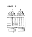
- Figure 4 is a plan view showing the band feeding roller and the band returning roller and the pulleys respectively connected to the rollers;
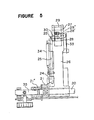
- Figure 5 is a side view of an inclinable lever as an important part of the present invention;
- Figure 6 is a diagram showing a mechanism of gripping, heat-bonding and cutting of the plastic band in association with cam means; and
- Figure 7 an enlarged diagram showing a part for returning the band according to the present invention.
- An embodiment of the present invention will be described with reference to the drawings.
- In Figure 1, a
reference numeral 100 designates as a whole a band type strapping machine in which the present invention is utilized. The strapping machine comprises amain body 101, aband guiding arch 102, a table 103 for receiving a package around which a plastic band is wound, aband reel 104 for holding theplastic band 105, a band feeding and returning roller means 106, a band tension adjusting means 107 operable in association with the band feeding and returning roller means 106, and a band gripping, heat-bonding and cutting means 108. - The internal structure of the band type strapping machine will be described in more detail.
- In Figures 2 to 4, the band feeding and returning roller means 106 comprises a band feeding roller 1 which is usually rotated in the band-feeding direction, a first pressing
roller 2 placed above the feeding roller 1 to be in press-contact with the feeding roller through the plastic band, aband returning roller 3 and a second pressing roller 4 disposed below theband returning roller 3 to be in press-contact with the returningroller 3. - A
first pulley 5 is integrally connected to the band feeding roller 1 through a first shaft, and asecond pulley 6 is integrally connected to theband returning roller 3 through a second shaft. A belt 7 is wound around thepulleys driving wheel 16 having a relatively large diameter. Thepulleys driving wheel 16. Anumeral 18 designates an idle roller. In the arrangement of the band feeding and returning rollers, both being rotated in the same direction as shown in Figure 2, the band feeding roller 1 operates to feed the band in the band-forwarding direction, while theband returning roller 3 operates to feed the band in the band returning direction because the firstpressing roller 2 is provided above the band feeding roller 1 and the second pressing roller 4 is placed below theband returning roller 3. Anumeral 9 designates a band guiding channel. - A
reference numeral 48 designates a right gripper which operates to secure the free end of the plastic band wound around the package on the table in association with asealing anvil 47 and which is provided the top end of thepush rod 44 vertically movable by the action of acam 42 depending on the revolution of acam shaft 14. Anumeral 50 designates a compression head which melt-bonds the inner surface of the free end of the plastic band wound around the package and the inner surface of the same band at the returning side, by pressing them from the lower part and which is provided at the top end of apush rod 44 vertically movable by means of thecam 42. Anumeral 44 designates aleft gripper 49 which secures the plastic band in association with thesealing anvil 47 after the band has been tightened by the action of theband returning roller 3, the free end of the band being previously secured between thesealing anvil 47 and theright gripper 48. Theleft gripper 49 is also provided at the top end of apush rod 44 which is vertically movable by thecam 42.Reference numerals 43 designate cam roller provided at the top of thecams 42. - The structure of the band tension adjusting means 107 will be described with reference to Figures 2, 5 and 7.
- A
tension lever 26 is attached to the machine frame of themain body 101 by apivotal shaft 20 so that the tension lever is oscillable around thepivotal shaft 20. Acam follower 22 attached to the base portion of thetension lever 26 is always in contact with the cam surface 23' of acam 23 which is attached to an end of thecam shaft 14 so as to move thetension lever 26 around thecam shaft 20 in accordance with the shape of the cam surface 23'. - A
slide bar 25 is provided along the longitudinal axis of thetension lever 26 so as to be slidable therealong. Aspring 34 is extended between the upper part of theslide bar 25 and a lower part of thetension lever 26, whereby theslide bar 26 is usually pulled downwardly. Acam roller 24 is attached at the lower end of theslide bar 25 so that thecam roller 24 rolls on the cam surface 21' of an adjustingcam 21. A boss 2111 of the adjustingcam 21 is firmly connected to an adjustingshaft 35 which is connected to thepivotal shaft 20 in the same axial line. The adjustingshaft 35 is provided with an adjustingpin 36 extending in the horizontal direction, and the head 36' of the adjustingpin 36 is inserted in a recess 37' formed in thebase portion 37 of an adjustingknob 38. - The top end 25' of the
slide bar 25 is engageable with an end of aU-shaped stopper 28. The other end 28' of the U-shapedstopper 28 is fitted in arecess 29" formed in agripper 29 which is pivotally supported by apin 27 extended in a forked portion formed at the upper part of thetension lever 26. - A
helical spring 30 is mounted on thegripper 29 with its one end engaged with thetension lever 26 so that thegripper 29 is always urged in the clockwise direction with the result that the plastic band is gripped between a slanting surface 29' formed in the lower part of thegripper 29 and a slanting surface 26' formed in the base of the forked portion of thetension lever 26. Aplate spring 33 pushes the U-shaped portion of thestopper 28 so that the one end 28' of thestopper 28 is always fitted in the recess 29'' of thegripper 29. Apin 32 is secured to thegripper 29, and thepin 32 is engageable with a-stoplever 31 as a fixed member. When thetension lever 26 is turned around thepivotal shaft 20 and thepin 32 of thegripper 29 comes to contact with thestop lever 31, the slanting surface 29' of thegripper 29 is disengaged with the slanting surface 26' of thetension lever 26, whereby theplastic band 105 is released. - When the
cam shaft 14 is rotated, hence thecam 23 is rotated, thetension lever 26 is moved in the clockwise direction around thepivotal shaft 20 since thecam follower 22 follows the cam surface 23' of thecam 23. Then, thepin 32 of thegripper 29 is disengaged with thestop lever 31. Thecam roller 24 at the lower end of thetension lever 26 moves along the cam surface 21' of the adjustingcam 21. -When thecam roller 24 reaches a point A on the cam surface 21', theslide bar 25 is pushed upwardly by the movement of thecam roller 24, whereby the upper end 25' of theslide bar 25 pushes the one end of the U-shapedstopper 28. Then, the other end 28' of thestopper 28 comes off the recess 29'' of thegripper 29, so that thegripper 29 becomes free. Accordingly, thegripper 29 turns by the action of thehelical spring 30 so that the plastic band is gripped between the slanting surface 29' of thegripper 29 and the slanting surface 26' of thetension lever 26. Since the tension lever is turned in the clockwise direction, the plastic band gripped is strongly pulled; thus, a strong tightening force is given to the band. - On completion of the band tightening operations, the
tension lever 26 is moved in the counterclockwise direction by the action of thecam 23, and thepin 32 of thegripper 29 comes in contact with thestopper lever 31, whereby thegripper 29 is returned to the original position, and the other end 28' of thestopper 28 is again fitted to therecess 29" of thegripper 29. The tightening force by thetension lever 26 can be adjusted by turning the adjustingknob 38, whereby the angular position of the adjusting shaft, i.e. the angle of the adjustingcam 21 with respect to thecam roller 24 is changed by means of the adjustingpin 36. The tightening force to the plastic band is in proportion to the length from the point where the band is gripped by thegripper 29 to the point where the tightening of the band is effected. - Figure 6 is a diagram showing the band gripping, heat-bonding, cutting means 108 which grips the band at two positions after the band is wound around the package and the band is pulled at its returning side; heat-bonds an overlapped portion of the band; and cutting the band. The sealing
anvil 47 is provided below the table for receiving the package. Theright gripper 48, theleft gripper 49 and thecompression head 50 are respectively fitted in insertion holes 45 formed in the first, second andthird levers 44, at the bottom of each of the insertion holes 45 apolyurethane spring 46 is placed. At the lower part of each of thelevers 44, a recess is formed, and thecam roller 43 is inserted in each of the recesses. The first, second andthird cams 42 which are fixed to thecam shaft 14 are respectively in contact with thecam rollers 43. The right gripper, the compression head and left gripper are pressed to the sealing anvil by therespective levers 44 through the polyurethane springs 45. Accordingly, quick operation is obtainable in response to the action of the cams in comparison with the conventional mechanism using coil springs. Further, the right and left grippers and the compression head can be operated with a constant pressure and with correct parallelism. - As described above, in the present invention, the construction of the band feeding and returning means is extremely simple to thereby reducing cost of manufacture and a smooth operation is attained without noise because the structure is driven by a single belt.
- Further, the cam attached to an end of the cam shaft provides timing for tightening of the band with a strong force. The rotation of the cam directly actuates the tension lever thereby performing tightening of the band. Accordingly, the strapping machine of the present invention can be formed compact and can be operated accurately.
- In addition, the tightening force of the band is easily adjusted by adjusting the angle of the adjusting shaft, i.e. the angle of the adjusting cam because the cam roller of the slide bar provided on the tension lever is brought to contact with the adjusting cam provided on the adjusting shaft and the operation of the gripper is controlled by the slide bar.
Claims (6)
Applications Claiming Priority (6)
| Application Number | Priority Date | Filing Date | Title |
|---|---|---|---|
| JP19897785U JPH0350011Y2 (en) | 1985-12-24 | 1985-12-24 | |
| JP198977/85U | 1985-12-24 | ||
| JP233786U JPH0356488Y2 (en) | 1986-01-11 | 1986-01-11 | |
| JP2337/86U | 1986-01-11 | ||
| JP16223/86U | 1986-02-06 | ||
| JP1986016223U JPH0136724Y2 (en) | 1986-02-06 | 1986-02-06 |
Publications (3)
| Publication Number | Publication Date |
|---|---|
| EP0231458A2 true EP0231458A2 (en) | 1987-08-12 |
| EP0231458A3 EP0231458A3 (en) | 1987-10-21 |
| EP0231458B1 EP0231458B1 (en) | 1990-02-28 |
Family
ID=27275307
Family Applications (1)
| Application Number | Title | Priority Date | Filing Date |
|---|---|---|---|
| EP86116162A Expired - Lifetime EP0231458B1 (en) | 1985-12-24 | 1986-11-21 | Band type strapping machine |
Country Status (5)
| Country | Link |
|---|---|
| US (1) | US4724659A (en) |
| EP (1) | EP0231458B1 (en) |
| KR (1) | KR900007360B1 (en) |
| CA (1) | CA1279253C (en) |
| DE (1) | DE3669132D1 (en) |
Cited By (4)
| Publication number | Priority date | Publication date | Assignee | Title |
|---|---|---|---|---|
| FR2616124A1 (en) * | 1987-06-04 | 1988-12-09 | Strapack Corp | WEB TIGHTENING APPARATUS OF A STRAPPING MACHINE |
| GB2255765A (en) * | 1990-05-04 | 1992-11-18 | Rmo Systempack Gmbh | Packing machine |
| EP1489005A2 (en) | 2003-06-20 | 2004-12-22 | Illinois Tool Works Inc. | Strapping machine with strap feeding and tensionning system with automatic refeed |
| IT201700001007A1 (en) * | 2017-01-10 | 2018-07-10 | Enrico Giampaoli | GUIDE TILE FOR STRAPPING MACHINE |
Families Citing this family (21)
| Publication number | Priority date | Publication date | Assignee | Title |
|---|---|---|---|---|
| US4912912A (en) * | 1987-05-30 | 1990-04-03 | Strapack Corporation | Control apparatus in strapping machine |
| CA1320427C (en) * | 1987-06-18 | 1993-07-20 | Yasunori Sakaki | Method and apparatus for feeding and tightening a band in strapping machine |
| DE3825668C1 (en) * | 1988-07-28 | 1990-02-15 | Signode Bernpak Gmbh, 5630 Remscheid, De | |
| DE4138800A1 (en) * | 1991-11-26 | 1993-05-27 | Signode Bernpak Gmbh | METHOD AND DEVICE FOR AVOIDING OPERATING INTERRUPTIONS ON MACHINES FOR STRAPPING PACKAGES |
| US5333438A (en) * | 1992-11-06 | 1994-08-02 | Signode Corporation | Dual coil power strapping machine |
| US5287802A (en) * | 1992-12-14 | 1994-02-22 | Signode Corporation | Strap severing and ejecting mechanism for strapping machine |
| US5377477A (en) * | 1993-12-09 | 1995-01-03 | Signode Corporation | Method and apparatus for a power strapping machine |
| US5459977A (en) * | 1993-12-09 | 1995-10-24 | Illinois Tool Works Inc. | Method and apparatus for an improved power strapping machine |
| DE19500085B4 (en) * | 1995-01-04 | 2006-04-27 | Smb Schwede Maschinenbau Gmbh | Apparatus for strapping packaged goods with a strapping band, in particular strapping machine for magazine stacks |
| DE59710674D1 (en) * | 1996-05-08 | 2003-10-09 | Orgapack Ag Dietikon | jig |
| US6018936A (en) * | 1998-12-03 | 2000-02-01 | Gin Dah Enterprises Corp. | Tape-leading mechanism for an automatic packer |
| DE19920725B4 (en) * | 1999-05-05 | 2004-08-26 | Strapex Holding Ag | clamping unit |
| US6415712B1 (en) | 1999-12-02 | 2002-07-09 | Enterprises International, Inc. | Track mechansim for guiding flexible straps around bundles of objects |
| EP1249397B1 (en) * | 2001-04-09 | 2005-01-19 | Nichiro Kogyo Co., Ltd. | Arch type strapping machine |
| US6584892B2 (en) * | 2001-07-12 | 2003-07-01 | Illinois Tool Works, Inc. | Strapping machine with modular heads |
| CN1764568A (en) * | 2003-01-24 | 2006-04-26 | 国际企业公司 | Apparatus and methods for applying a strap around a bundle of objects |
| CH698112B1 (en) * | 2005-09-05 | 2009-05-29 | Ats Tanner Banding Systems Ag | Banding a stack of articles. |
| CH705743A2 (en) | 2011-11-14 | 2013-05-15 | Illinois Tool Works | Strapper. |
| PL3105126T3 (en) | 2014-02-10 | 2018-11-30 | Orgapack Gmbh | Tensioning device for a strapping device |
| DE102014110247A1 (en) * | 2014-07-21 | 2016-01-21 | Krones Aktiengesellschaft | Apparatus for tensioning a strapping band, strapping head equipped therewith and method of tensioning a strapping band |
| USD864688S1 (en) | 2017-03-28 | 2019-10-29 | Signode Industrial Group Llc | Strapping device |
Citations (3)
| Publication number | Priority date | Publication date | Assignee | Title |
|---|---|---|---|---|
| US4306400A (en) * | 1980-02-07 | 1981-12-22 | Rexham Corporation | Packaging machine with continuous motion top sealer |
| US4383881A (en) * | 1981-09-17 | 1983-05-17 | Strapack Shimojima Co., Ltd. | Strapping machine |
| EP0203278A2 (en) * | 1985-05-02 | 1986-12-03 | Signode Corporation | Method and apparatus for feeding and tensioning strap in a strapping machine |
Family Cites Families (3)
| Publication number | Priority date | Publication date | Assignee | Title |
|---|---|---|---|---|
| US171560A (en) * | 1875-12-28 | Improvement in cotton-bale-band tighteners | ||
| US3309839A (en) * | 1963-09-26 | 1967-03-21 | Halm Instrument Co | Package banding machine |
| US3665845A (en) * | 1970-10-12 | 1972-05-30 | Halm Instrument Co | Banding means |
-
1986
- 1986-11-07 US US06/928,166 patent/US4724659A/en not_active Expired - Lifetime
- 1986-11-21 EP EP86116162A patent/EP0231458B1/en not_active Expired - Lifetime
- 1986-11-21 DE DE8686116162T patent/DE3669132D1/en not_active Expired - Lifetime
- 1986-11-27 CA CA000524003A patent/CA1279253C/en not_active Expired - Lifetime
- 1986-11-29 KR KR1019860010172A patent/KR900007360B1/en not_active IP Right Cessation
Patent Citations (3)
| Publication number | Priority date | Publication date | Assignee | Title |
|---|---|---|---|---|
| US4306400A (en) * | 1980-02-07 | 1981-12-22 | Rexham Corporation | Packaging machine with continuous motion top sealer |
| US4383881A (en) * | 1981-09-17 | 1983-05-17 | Strapack Shimojima Co., Ltd. | Strapping machine |
| EP0203278A2 (en) * | 1985-05-02 | 1986-12-03 | Signode Corporation | Method and apparatus for feeding and tensioning strap in a strapping machine |
Cited By (6)
| Publication number | Priority date | Publication date | Assignee | Title |
|---|---|---|---|---|
| FR2616124A1 (en) * | 1987-06-04 | 1988-12-09 | Strapack Corp | WEB TIGHTENING APPARATUS OF A STRAPPING MACHINE |
| GB2255765A (en) * | 1990-05-04 | 1992-11-18 | Rmo Systempack Gmbh | Packing machine |
| GB2255765B (en) * | 1990-05-04 | 1995-04-19 | Rmo Systempack Gmbh | Packing machine |
| EP1489005A2 (en) | 2003-06-20 | 2004-12-22 | Illinois Tool Works Inc. | Strapping machine with strap feeding and tensionning system with automatic refeed |
| EP1489005A3 (en) * | 2003-06-20 | 2012-02-22 | Illinois Tool Works Inc. | Strapping machine with strap feeding and tensionning system with automatic refeed |
| IT201700001007A1 (en) * | 2017-01-10 | 2018-07-10 | Enrico Giampaoli | GUIDE TILE FOR STRAPPING MACHINE |
Also Published As
| Publication number | Publication date |
|---|---|
| DE3669132D1 (en) | 1990-04-05 |
| KR870005870A (en) | 1987-07-07 |
| CA1279253C (en) | 1991-01-22 |
| US4724659A (en) | 1988-02-16 |
| KR900007360B1 (en) | 1990-10-08 |
| EP0231458B1 (en) | 1990-02-28 |
| EP0231458A3 (en) | 1987-10-21 |
Similar Documents
| Publication | Publication Date | Title |
|---|---|---|
| US4724659A (en) | Band type strapping machine | |
| US5126002A (en) | Leaf paper bundling apparatus | |
| US4559767A (en) | Apparatus for regulating the tension of a strap in a package strapping machine | |
| US4655264A (en) | Twist tying machine | |
| US4845928A (en) | Band loading apparatus in a packaging machine | |
| EP0144508B1 (en) | Band-returning and tightening apparatus for a band type strapping machine | |
| GB2048814A (en) | Strapping machine adaptable for automatic or semi-automatic use | |
| EP0139462B1 (en) | Twist tying machine | |
| JPH0126926B2 (en) | ||
| GB2059010A (en) | Tension adjusting mechanism for article binding machine | |
| US4362096A (en) | Tying machine | |
| EP0041236A1 (en) | Slide fastener finishing machine | |
| JPS6340406Y2 (en) | ||
| JPS6350047Y2 (en) | ||
| US3587449A (en) | Apparatus for applying locking sleeves to tying material | |
| JPH035527Y2 (en) | ||
| WO2003079380A1 (en) | Toroidal core winding machine | |
| US3039380A (en) | Wire tying machines | |
| JPH04242507A (en) | Band tensioner in packer | |
| JPS6341294Y2 (en) | ||
| JPS59185676A (en) | Sheet supplying device | |
| JPS6340407Y2 (en) | ||
| JPH0311127Y2 (en) | ||
| JPH024446B2 (en) | ||
| JPH0136724Y2 (en) |
Legal Events
| Date | Code | Title | Description |
|---|---|---|---|
| PUAI | Public reference made under article 153(3) epc to a published international application that has entered the european phase |
Free format text: ORIGINAL CODE: 0009012 |
|
| AK | Designated contracting states |
Kind code of ref document: A2 Designated state(s): CH DE FR GB LI NL |
|
| PUAL | Search report despatched |
Free format text: ORIGINAL CODE: 0009013 |
|
| AK | Designated contracting states |
Kind code of ref document: A3 Designated state(s): CH DE FR GB LI NL |
|
| 17P | Request for examination filed |
Effective date: 19880212 |
|
| 17Q | First examination report despatched |
Effective date: 19880909 |
|
| GRAA | (expected) grant |
Free format text: ORIGINAL CODE: 0009210 |
|
| AK | Designated contracting states |
Kind code of ref document: B1 Designated state(s): CH DE FR GB LI NL |
|
| REF | Corresponds to: |
Ref document number: 3669132 Country of ref document: DE Date of ref document: 19900405 |
|
| ET | Fr: translation filed | ||
| PLBE | No opposition filed within time limit |
Free format text: ORIGINAL CODE: 0009261 |
|
| STAA | Information on the status of an ep patent application or granted ep patent |
Free format text: STATUS: NO OPPOSITION FILED WITHIN TIME LIMIT |
|
| 26N | No opposition filed | ||
| PGFP | Annual fee paid to national office [announced via postgrant information from national office to epo] |
Ref country code: FR Payment date: 19941109 Year of fee payment: 9 |
|
| PGFP | Annual fee paid to national office [announced via postgrant information from national office to epo] |
Ref country code: GB Payment date: 19941111 Year of fee payment: 9 |
|
| PGFP | Annual fee paid to national office [announced via postgrant information from national office to epo] |
Ref country code: NL Payment date: 19941130 Year of fee payment: 9 |
|
| PG25 | Lapsed in a contracting state [announced via postgrant information from national office to epo] |
Ref country code: GB Effective date: 19951121 |
|
| PG25 | Lapsed in a contracting state [announced via postgrant information from national office to epo] |
Ref country code: NL Effective date: 19960601 |
|
| GBPC | Gb: european patent ceased through non-payment of renewal fee |
Effective date: 19951121 |
|
| PG25 | Lapsed in a contracting state [announced via postgrant information from national office to epo] |
Ref country code: FR Effective date: 19960731 |
|
| NLV4 | Nl: lapsed or anulled due to non-payment of the annual fee |
Effective date: 19960601 |
|
| REG | Reference to a national code |
Ref country code: FR Ref legal event code: ST |
|
| PGFP | Annual fee paid to national office [announced via postgrant information from national office to epo] |
Ref country code: DE Payment date: 20041122 Year of fee payment: 19 |
|
| PGFP | Annual fee paid to national office [announced via postgrant information from national office to epo] |
Ref country code: CH Payment date: 20041129 Year of fee payment: 19 |
|
| PG25 | Lapsed in a contracting state [announced via postgrant information from national office to epo] |
Ref country code: LI Free format text: LAPSE BECAUSE OF NON-PAYMENT OF DUE FEES Effective date: 20051130 Ref country code: CH Free format text: LAPSE BECAUSE OF NON-PAYMENT OF DUE FEES Effective date: 20051130 |
|
| PG25 | Lapsed in a contracting state [announced via postgrant information from national office to epo] |
Ref country code: DE Free format text: LAPSE BECAUSE OF NON-PAYMENT OF DUE FEES Effective date: 20060601 |
|
| REG | Reference to a national code |
Ref country code: CH Ref legal event code: PL |