EP0230822A1 - Flow regulating distribution circuit - Google Patents
Flow regulating distribution circuit Download PDFInfo
- Publication number
- EP0230822A1 EP0230822A1 EP86402841A EP86402841A EP0230822A1 EP 0230822 A1 EP0230822 A1 EP 0230822A1 EP 86402841 A EP86402841 A EP 86402841A EP 86402841 A EP86402841 A EP 86402841A EP 0230822 A1 EP0230822 A1 EP 0230822A1
- Authority
- EP
- European Patent Office
- Prior art keywords
- flow
- section
- fluid
- leakage
- flow sensor
- Prior art date
- Legal status (The legal status is an assumption and is not a legal conclusion. Google has not performed a legal analysis and makes no representation as to the accuracy of the status listed.)
- Granted
Links
Images

Classifications
-
- B—PERFORMING OPERATIONS; TRANSPORTING
- B67—OPENING, CLOSING OR CLEANING BOTTLES, JARS OR SIMILAR CONTAINERS; LIQUID HANDLING
- B67D—DISPENSING, DELIVERING OR TRANSFERRING LIQUIDS, NOT OTHERWISE PROVIDED FOR
- B67D7/00—Apparatus or devices for transferring liquids from bulk storage containers or reservoirs into vehicles or into portable containers, e.g. for retail sale purposes
- B67D7/06—Details or accessories
- B67D7/36—Arrangements of flow- or pressure-control valves
-
- G—PHYSICS
- G05—CONTROLLING; REGULATING
- G05D—SYSTEMS FOR CONTROLLING OR REGULATING NON-ELECTRIC VARIABLES
- G05D7/00—Control of flow
- G05D7/03—Control of flow with auxiliary non-electric power
Definitions
- the subject of the invention is a flow regulation device adapted to ensure, without costly slaving, a progressive and continuous regulation of the speed of the associated pump, hence a regular flow of fluid.
- the diameter of the disc and the force of the return member determine, in practice, the axial stroke of the sliding shaft while the sleeve is adjusted axially along the shaft so as to obtain a variation in the leakage rate. after a minimum (possibly zero) stroke of the shaft.
- the invention further provides a fluid distribution circuit comprising a pipe between a pump and a distribution member, this pump being equipped with a fluid recirculation valve ("by-pass") and driven by a motor controlled by an accelerator member, this valve and this acceleration member being supplied by an air duct, characterized in that it comprises, downstream of the pump, a section of duct secured to a flow regulator comprising, in a body, a mobile flow sensor adapted to take a variable position as a function of the instantaneous flow in this section, an air passage duct connects to the air duct and from where a leakage channel leaves, and a mobile leakage control member coupled to the mobile flow sensor, and adapted to adjust the air leakage section to a variable level which is a function of the variable position of the flow sensor.
- a fluid recirculation valve by-pass
- the flow regulator can also be engaged in a straight section of pipe, being entirely included.
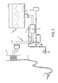
- FIG. 1 The installation of FIG. 1 comprises a tank 1 filled with a fluid, petrol or kerosene for example, intended to be dispensed using a dispensing gun 2.
- This tank 1 is equipped with a pipe 3 which starts from a valve 4 with which this tank is provided at its bottom, passes through a pump 5 associated with a combustion engine (within a compressor group), then a counter 6, and is connected to a pipe flexible 7, wound on a drum 8, terminated by said gun 2.
- the motor of the pump 5 is for example the motor of a truck carrying the tank 1. It is placed under the control of a control member 10, such as an accelerator cylinder, which is controlled, as well as a bypass 9 with which this pump is equipped, by an air flow coming from a source 11. As is known, this bypass is a valve which controls the recirculation of the fluid in the pump.
- This flow regulator 12 is shown on a larger scale in FIG. 2.
- the sliding shaft 14 is subjected to a restoring force which tends to bring it back into a configuration in which it prevents as little as possible an escape of air through the channel 18.
- This shaft thus comprises a shoulder 19 on which a spring 20 which surrounds the shaft applies and bears at its other end on a shoulder 21 of the body 13.
- This shoulder 19 is advantageously provided on a ring 22 of this shaft so to provide a stop 23 adapted to be applied against a bearing surface 24 of the body 13 at the end of the travel of the shaft 14.
- the engagement of this shaft and of this spring in the body 13 requires that the latter be in two parts 13A and 13B respectively carrying the shoulders 21 and 24.
- the chamber 16 has a bore 25 from which radially offset conduits 26 leave radially connecting this chamber to the channel 18.
- a sleeve 27 sliding in leaktight manner in the bore 25 and closing a variable number of conduits 26.
- This sleeve 27 is advantageously adjustable along the shaft, using complementary threaded portions 14A and 27A. This adjustment can be made on site, after temporary removal of a cap 28 closing the rear part of the bore 25.
- the elbow 3A is shaped so as to present a constriction 32 in the vicinity of the disc 15.
- a flow regulator according to the invention can be arranged in a straight portion of pipe, along the axis of this portion, while being entirely included in this portion.
- the shaft of this regulator can also be mounted so as to be, at rest, in the maximum extension configuration, the regulating disc then being disposed upstream relative to the regulator body.
Landscapes
- Engineering & Computer Science (AREA)
- Power Engineering (AREA)
- Physics & Mathematics (AREA)
- General Physics & Mathematics (AREA)
- Automation & Control Theory (AREA)
- Mechanical Engineering (AREA)
- Flow Control (AREA)
- Control Of Positive-Displacement Pumps (AREA)
- Structures Of Non-Positive Displacement Pumps (AREA)
Abstract
Description
La présente invention concerne un dispositif de régulation de débit adapté à réguler le débit d'une pompe entraînant un fluide dans une canalisation en fonction du réglage d'un organe de distribution monté en aval de cette canalisation. Elle concerne également un circuit de distribution de fluide comportant ce dispositif de régulation de débit.The present invention relates to a flow control device adapted to regulate the flow of a pump driving a fluid in a pipe as a function of the setting of a distribution member mounted downstream of this pipe. It also relates to a fluid distribution circuit comprising this flow regulation device.
L'invention est notamment applicable à la distribution d'un carburant (essence, kérosène) à partir d'une citerne, par exemple portée par un camion-citerne.The invention is particularly applicable to the distribution of a fuel (petrol, kerosene) from a tank, for example carried by a tank truck.
On connaît déjà des dispositifs de régulation de débit du type précité, mais ceux-ci fonctionnent en tout ou rien, d'où une régulation de débit par à-coups ; les dispositifs de régulation déjà connus sont généralement complexes et coûteux.Flow control devices of the aforementioned type are already known, but these operate all or nothing, hence a flow regulation in spurts; the control devices already known are generally complex and expensive.
L'invention a pour objet un dispositif de régulation de débit adapté à assurer, sans asservissement coûteux, une régulation progressive et continue du régime de la pompe associée, d'où un écoulement régulier de fluide.The subject of the invention is a flow regulation device adapted to ensure, without costly slaving, a progressive and continuous regulation of the speed of the associated pump, hence a regular flow of fluid.
L'invention propose ainsi un dispositif de régulation de débit destiné à être monté sur une canalisation de distribution de fluide en aval d'une pompe dont le régime est sensible à un écoulement de fluide de commande dans un organe de réglage, caractérisé en ce qu'il comporte, dans un corps adapté à être lié à un tronçon de la canalisation, un capteur mobile de débit adapté à prendre une position variable en fonction du débit instantané dans ce tronçon, un conduit de traversée de fluide de commande d'où part un canal de fuite, et un organe mobile de régulation de fuite, attelé au capteur mobile de débit, et adapté à ajuster la section de passage de fuite à un niveau variable qui est fonction de la position variable du capteur de débit.The invention thus provides a flow control device intended to be mounted on a fluid distribution pipe downstream of a pump whose speed is sensitive to a flow of control fluid in an adjustment member, characterized in that 'it comprises, in a body adapted to be linked to a section of the pipe, a mobile flow sensor adapted to assume a variable position as a function of the instantaneous flow in this section, a conduit for crossing the control fluid from which a leakage channel, and a mobile leakage control member, coupled to the mobile flow sensor, and adapted to adjust the leakage passage section to a variable level which is a function of the variable position of the flow sensor.
Selon des dispositions préférées de l'invention, le capteur de débit et l'organe de régulation de fuite sont portés par un arbre coulissant soumis à un organe de rappel tendant à ramener l'arbre dans une position correspondant à un débit minimal et un débit de fuite maximal. Ce capteur de débit est avantageusement constitué d'un disque destiné à être disposé transversalement à l'écoulement de fluide. L'organe de régulation de fuite est de préférence un manchon porté par l'arbre, de façon avantageusement réglable, coulissant dans un alésage relié au conduit de traversée de fluide et communiquant avec le canal de fuite par des conduits radiaux décalés axialement en sorte de pouvoir être progressivement obturés par ce manchon lors de son mouvement axial.According to preferred arrangements of the invention, the flow sensor and the leakage regulating member are carried by a sliding shaft subjected to a return member tending to return the shaft to a position corresponding to a minimum flow rate and a flow rate maximum leakage. This flow sensor advantageously consists of a disc intended to be arranged transversely to the flow of fluid. The leakage regulating member is preferably a sleeve carried by the shaft, advantageously adjustable, sliding in a bore connected to the fluid passage duct and communicating with the leakage channel by radial ducts offset axially so as to be able to be gradually closed by this sleeve during its axial movement.
Le diamètre du disque et la force de l'organe de rappel déterminent, en pratique, la course axiale de l'arbre coulissant tandis que le manchon est réglé axialement le long de l'arbre en sorte d'obtenir une variation du débit de fuite après une course minimale (éventuellement nulle) de l'arbre.The diameter of the disc and the force of the return member determine, in practice, the axial stroke of the sliding shaft while the sleeve is adjusted axially along the shaft so as to obtain a variation in the leakage rate. after a minimum (possibly zero) stroke of the shaft.
L'invention propose en outre un circuit de distribution de fluide comportant une canalisation entre une pompe et un organe de distribution, cette pompe étant équipée d'une valve de recirculation de fluide ("by-pass") et entraînée par un moteur commandé par un organe d'accélérateur, cette valbe et cet organe d'accélération étant alimentés par une canalisation d'air, caractérisé en ce qu'il comporte, en aval de la pompe, un tronçon de canalisation solidaire d'un régulateur de débit comportant, dans un corps, un capteur mobile de débit adapté à prendre une position variable en fonction du débit instantané dans ce tronçon, un conduit de traversée d'air relie à la canalisation d'air et d'où part un canal de fuite, et un organe mobile de régulation de fuite attelé au capteur mobile de débit, et adapté à ajuster la section de fuite d'air à un niveau variable qui est fonction de la position variable du capteur de débit.The invention further provides a fluid distribution circuit comprising a pipe between a pump and a distribution member, this pump being equipped with a fluid recirculation valve ("by-pass") and driven by a motor controlled by an accelerator member, this valve and this acceleration member being supplied by an air duct, characterized in that it comprises, downstream of the pump, a section of duct secured to a flow regulator comprising, in a body, a mobile flow sensor adapted to take a variable position as a function of the instantaneous flow in this section, an air passage duct connects to the air duct and from where a leakage channel leaves, and a mobile leakage control member coupled to the mobile flow sensor, and adapted to adjust the air leakage section to a variable level which is a function of the variable position of the flow sensor.
Selon des dispositions préférées de l'invention, le canal de fuite est avantageusement raccordé à la canalisation d'alimentation d'air en amont du régulateur de débit. Ce régulateur est avantageusement monté sur une portion coudée de la canalisation de distribution. Le capteur de débit est avantageusement un disque adapté à s'éloigner du corps du régulateur de débit pour des débits croissants d'écoulement.According to preferred arrangements of the invention, the leakage channel is advantageously connected to the air supply pipe upstream of the flow regulator. This regulator is advantageously mounted on a bent portion of the distribution pipe. The flow sensor is advantageously a disc adapted to move away from the body of the flow regulator for increasing flow rates.
Le régulateur de débit peut aussi être engagé dans un tronçon rectiligne de canalisation, en y étant entièrement inclus.The flow regulator can also be engaged in a straight section of pipe, being entirely included.
Les objets, caractéristiques et avantages de l'invention ressortent de la description qui suit, donnée à titre d'exemple non limitatif, en regard des dessins annexés sur lesquels :
- - la figure 1 est un schéma synoptique d'une installation d'alimentation en fluide mettant en oeuvre un régulateur de débit selon l'invention, et
- - la figure 2 est une vue en coupe, selon l'encadré II de la figure 1, de ce régulateur de débit.
- FIG. 1 is a block diagram of a fluid supply installation using a flow regulator according to the invention, and
- - Figure 2 is a sectional view, according to Box II of Figure 1, of this flow regulator.
L'installation de la figure 1 comporte une citerne 1 remplie d'un fluide, de l'essence ou du kérosène par exemple, destiné à être distribué à l'aide d'un pistolet de distribution 2. Cette citerne 1 est équipée d'une canalisation 3 qui part d'un clapet 4 dont cette citerne est munie en son fond, traverse une pompe 5 associée à un moteur à combustion (au sein d'un groupe compresseur), puis un compteur 6, et est raccordée à une canalisation souple 7, enroulée sur un tambour 8, terminée par ledit pistolet 2.The installation of FIG. 1 comprises a tank 1 filled with a fluid, petrol or kerosene for example, intended to be dispensed using a dispensing gun 2. This tank 1 is equipped with a
Le moteur de la pompe 5 est par exemple le moteur d'un camion portant la citerne 1. Il est placé sous le contrôle d'un organe de commande 10, tel qu'un vérin d'accélérateur, qui est contrôlé, ainsi qu'un by-pass 9 dont cette pompe est équipée, par un débit d'air en provenance d'une source 11. Ainsi qu'on le sait, ce by-pass est une valve qui contrôle la recirculation du fluide dans la pompe.The motor of the
Sur la canalisation 3, de préférence juste en aval de la pompe, est localisé, avantageusement sur une portion en coude de cette canalisation, un régulateur de débit 12 selon l'invention qui est par ailleurs intercalé entre la source 11, et le by-pass 9 et l'organe de commande 10.On the
Ce régulateur de débit 12 est représenté à plus grande échelle à la figure 2.This
Il comporte un corps 13 rendu solidaire de la portion en coude 3A de la canalisation 3. Dans ce corps est monté un arbre coulissant 14 comportant à une extrémité un disque 15 adapté à obturer au moins partiellement la section de passage du fluide au travers du coude 3A. Selon la position de l'arbre dans le corps, le disque 15 obture de façon variable la section d'écoulement du fluide dans ce coude.It comprises a
Ce corps 13 comporte une chambre 16 (ou conduit de traversée d'air) traversée par la canalisation 17 reliant la source d'air 11 au by-pass 9 et au vérin 10, et d'où part un canal de fuite 18 adapté à ramener une portion de l'air incident vers la canalisation 17 en amont dudit corps 13. Cette chambre 16 est traversée par l'arbre coulissant 14 de telle sorte que la section d'écoulement de l'air ramené vers la canalisation 17 par le canal de dérivation 18 dépend de la position de l'arbre par rapport au corps 13.This
Il s'établit ainsi une relation entre la section d'écoulement du fluide dans le coude 3A et la section d'écoulement de l'air dans le canal 18, et donc une relation entre le débit de fluide dans le coude 3A et le débit ou la pression d'air appliquée au by-pass 9 et au vérin 10. La configuration du coude 3A et du régulateur de débit 12 est telle que ces débits varient dans le même sens.There is thus established a relationship between the fluid flow section in the
L'arbre coulissant 14 est soumis à une force de rappel qui tend à le ramener dans une configuration dans laquelle il empêche aussi peu que possible un échappement d'air par le canal 18.The sliding
Cet arbre comporte ainsi un épaulement 19 sur lequel s'applique un ressort 20 qui entoure l'arbre et prend appui à son autre extrémité sur un épaulement 21 du corps 13. Cet épaulement 19 est avantageusement prévu sur une bague 22 de cet arbre en sorte de ménager une butée 23 adaptée à venir s'appliquer contre une portée 24 du corps 13 en fin de course de l'arbre 14. L'engagement de cet arbre et de ce ressort dans le corps 13 nécessite que celui-ci soit en deux parties 13A et 13B portant respectivement les épaulements 21 et 24.This shaft thus comprises a
La chambre 16 comporte un alésage 25 d'où partent radialement des conduits 26 décalés axialement reliant cette chambre au canal 18. Sur l'arbre 14 est monté un manchon 27 coulissant de façon étanche dans l'alésage 25 et obturant un nombre variable de conduits 26. Ce manchon 27 est avantageusement réglable le long de l'arbre, à l'aide de portions filetées complémentaires 14A et 27A. Ce réglage peut être effectué sur place, après retrait temporaire d'un capuchon 28 obturant la partie arrière de l'alésage 25.The
Divers organes d'étanchéité et de lubrification sont prévus le long de l'arbre coulissant 14. Ainsi un joint d'étanchéité à lèvres 29 est prévu à la partie avant du corps 13 pour empêcher la remontée du fluide circulant dans le coude 3A le long de l'arbre ; en vue d'assurer toutefois une auto-lubrification contrôlée, des cavités 30 en nombre approprié sont ménagées dans cet arbre à proximité du joint 29. De même, à des fins d'auto-lubrification contrôlée, un gorge 31 est évidée dans l'arbre en arrière de la bague 22 pour permettre un glissement aisé de l'arbre dans la partie 13B du corps 13. Diverses bagues d'étanchéité sont par ailleurs prévues entre le coude et le corps 13, entre les deux parties de ce dernier, et entre le manchon 27 et l'arbre et la partie 13B.Various sealing and lubrication members are provided along the
Dans l'exemple de la figure 2, le coude 3A est conformé en sorte de présenter un étranglement 32 au voisinage du disque 15.In the example of FIG. 2, the
En fonctionnement, tant que le pistolet 2 est fermé, il ne s'écoule que peu ou pas de fluide dans le coude 3A ; sous l'action du ressort 20, l'arbre 14 reste en position rétractée, et le manchon 27 n'obture aucun conduit 26 ; la pression appliquée au by-pass est alors minimale en raison de l'important débit d'air qui est dérivé par le canal 18. Le by-pass est ouvert, le moteur tourne au ralenti et la pompe ne délivre pas (ou peu) de débit.In operation, as long as the gun 2 is closed, little or no fluid flows through the
Dès que l'on ouvre le pistolet, du fluide s'écoule ce qui se traduit par une dépression en aval du disque 15 ; cela provoque la sortie de l'arbre, et donc l'obturation progressive des conduits 26 par le manchon 27. La quantité d'air dérivée par le canal 18 est ainsi réduite, d'où une augmentation de la pression appliquée au by-pass et au vérin d'accélérateur. Il en résulte une accélération du moteur et la fermeture du by-pass, d'où une augmentation du débit fourni par la pompe, jusqu'à équilibrer la dépression subie par le disque 15 qui reste alors en une position d'équilibre pour laquelle la pompe fournit le débit demandé au pistolet. Il y a ainsi autorégulation du débit à un niveau quelconque.As soon as the gun is opened, fluid flows, which results in a vacuum downstream of the
Lorsque l'on relâche le pistolet, le phénomène inverse a lieu, avec ralentissement du moteur et ouverture du by-pass.When the gun is released, the opposite phenomenon takes place, with the engine slowing down and the bypass opening.
Il va de soi que la description qui précède n'a été proposée qu'à titre d'exemple non limitatif et que de nombreuses variantes peuvent être proposées par l'homme de l'art sans sortir cu cadre de l'invention. Ainsi, notamment, un régulateur de débit selon l'invention peut être disposé dans une portion droite de canalisation, selon l'axe de cette portion, en étant entièrement inclus dans cette portion. L'arbre de ce régulateur peut par ailleurs être monté en sorte d'être, au repos, en configuration d'extension maximale, le disque de régulation étant alors disposé en amont par rapport au corps de régulateur.It goes without saying that the above description has been offered only by way of nonlimiting example and that numerous variants can be proposed by those skilled in the art without departing from the scope of the invention. Thus, in particular, a flow regulator according to the invention can be arranged in a straight portion of pipe, along the axis of this portion, while being entirely included in this portion. The shaft of this regulator can also be mounted so as to be, at rest, in the maximum extension configuration, the regulating disc then being disposed upstream relative to the regulator body.
Claims (10)
Applications Claiming Priority (2)
| Application Number | Priority Date | Filing Date | Title |
|---|---|---|---|
| FR8518957 | 1985-12-20 | ||
| FR8518957A FR2592189B1 (en) | 1985-12-20 | 1985-12-20 | DEVICE FOR CONTROLLING THE FLOW OF A PUMP AND FLUID DISTRIBUTION CIRCUIT COMPRISING SAME |
Publications (2)
| Publication Number | Publication Date |
|---|---|
| EP0230822A1 true EP0230822A1 (en) | 1987-08-05 |
| EP0230822B1 EP0230822B1 (en) | 1990-05-02 |
Family
ID=9326034
Family Applications (1)
| Application Number | Title | Priority Date | Filing Date |
|---|---|---|---|
| EP19860402841 Expired - Lifetime EP0230822B1 (en) | 1985-12-20 | 1986-12-17 | Flow regulating distribution circuit |
Country Status (3)
| Country | Link |
|---|---|
| EP (1) | EP0230822B1 (en) |
| DE (1) | DE3670824D1 (en) |
| FR (1) | FR2592189B1 (en) |
Cited By (1)
| Publication number | Priority date | Publication date | Assignee | Title |
|---|---|---|---|---|
| EP0440845A1 (en) * | 1990-02-07 | 1991-08-14 | Scheidt & Bachmann Gmbh | Tap device to dispense fluid fuels |
Citations (4)
| Publication number | Priority date | Publication date | Assignee | Title |
|---|---|---|---|---|
| GB490515A (en) * | 1936-06-15 | 1938-08-15 | Wayne Co | Improvements in or relating to pumping devices particularly for use in connection with liquid dispensing apparatus |
| FR1444204A (en) * | 1965-05-20 | 1966-07-01 | Advanced detector apparatus | |
| FR2445177A1 (en) * | 1978-12-28 | 1980-07-25 | Lestradet M C J | IMPROVEMENTS ON CONTROLLED FLOW SPREADING DEVICES |
| DE3346000A1 (en) * | 1982-12-21 | 1984-06-28 | Linde Ag, 6200 Wiesbaden | Hydraulic actuating device for a hydrostatic machine |
-
1985
- 1985-12-20 FR FR8518957A patent/FR2592189B1/en not_active Expired
-
1986
- 1986-12-17 EP EP19860402841 patent/EP0230822B1/en not_active Expired - Lifetime
- 1986-12-17 DE DE8686402841T patent/DE3670824D1/en not_active Expired - Lifetime
Patent Citations (4)
| Publication number | Priority date | Publication date | Assignee | Title |
|---|---|---|---|---|
| GB490515A (en) * | 1936-06-15 | 1938-08-15 | Wayne Co | Improvements in or relating to pumping devices particularly for use in connection with liquid dispensing apparatus |
| FR1444204A (en) * | 1965-05-20 | 1966-07-01 | Advanced detector apparatus | |
| FR2445177A1 (en) * | 1978-12-28 | 1980-07-25 | Lestradet M C J | IMPROVEMENTS ON CONTROLLED FLOW SPREADING DEVICES |
| DE3346000A1 (en) * | 1982-12-21 | 1984-06-28 | Linde Ag, 6200 Wiesbaden | Hydraulic actuating device for a hydrostatic machine |
Cited By (1)
| Publication number | Priority date | Publication date | Assignee | Title |
|---|---|---|---|---|
| EP0440845A1 (en) * | 1990-02-07 | 1991-08-14 | Scheidt & Bachmann Gmbh | Tap device to dispense fluid fuels |
Also Published As
| Publication number | Publication date |
|---|---|
| DE3670824D1 (en) | 1990-06-07 |
| FR2592189B1 (en) | 1988-04-01 |
| FR2592189A1 (en) | 1987-06-26 |
| EP0230822B1 (en) | 1990-05-02 |
Similar Documents
| Publication | Publication Date | Title |
|---|---|---|
| EP2326811B1 (en) | Device for controlling the fluid supply of a system | |
| FR2511328A1 (en) | HYDROSTATIC ASSISTED STEERING | |
| EP1947385B1 (en) | Fuel injection device in a turbomachine | |
| EP1312864B1 (en) | Dosing device for turbomachine fuel injector | |
| FR2463271A1 (en) | FUEL INJECTION PUMP FOR INTERNAL COMBUSTION ENGINES | |
| FR2476228A1 (en) | FUEL INJECTION PUMP APPARATUS | |
| FR2764649A1 (en) | FUEL METERING VALVE FOR A FUEL INJECTION SYSTEM OF AN INTERNAL COMBUSTION ENGINE | |
| EP0230822B1 (en) | Flow regulating distribution circuit | |
| FR2646212A1 (en) | APPARATUS FOR CIRCULATING AND DISPENSING FLUID | |
| FR2585485A1 (en) | FUEL ASSAY SYSTEM | |
| EP0991857B1 (en) | Decelerator device mounted in the exhaust gas circuit of a vehicle equipped with a combustion engine | |
| EP0021259B1 (en) | Control device for a lock-up clutch of a hydrodynamic torque converter | |
| FR2461826A1 (en) | FUEL INJECTION PUMP FOR INTERNAL COMBUSTION ENGINES | |
| FR2718190A1 (en) | Fuel injection control valve for a turbomachine. | |
| FR2671144A1 (en) | Device for controlling an autonomous thrust cylinder | |
| FR2611236A1 (en) | HYDRAULIC PISTON WITH AXIAL PISTONS PROVIDED WITH VALVES ANTI RETURN RETURN HYDRAULICALLY CONTROLLED | |
| FR2573151A1 (en) | HYDRAULIC CIRCUIT FOR HYDRODYNAMIC COUPLING MEMBER | |
| FR2461882A1 (en) | Oil pump for small two=stroke engines - has reciprocating piston in cylinder offset in rotating distributor driven by worm gear | |
| FR2479399A1 (en) | PNEUMATICALLY ASSISTED RESTRAINT VALVE | |
| FR2651341A1 (en) | Flow rate or pressure regulator | |
| FR2476224A1 (en) | FUEL INJECTION PUMP APPARATUS FOR COMPRESSION IGNITION ENGINE | |
| FR2610998A1 (en) | FUEL INJECTION PUMP FOR INTERNAL COMBUSTION ENGINES, ALLOWING THE REMOVAL OF ALL OR PART OF THE WATER CONTAINED IN THE FUEL | |
| FR2491143A1 (en) | FUEL CONTROL SYSTEM AND DEVICE FOR A GAS TURBINE MACHINE | |
| FR2821387A1 (en) | Device for introduction of fuel mixture into two-stroke engine combustion chamber comprises valve and element connected to valve delimiting upper and lower chambers, pressurized air supply and fluidic communication between chambers | |
| FR2543615A1 (en) | Pressure adjusting device, especially for an internal combustion engine oil pump |
Legal Events
| Date | Code | Title | Description |
|---|---|---|---|
| PUAI | Public reference made under article 153(3) epc to a published international application that has entered the european phase |
Free format text: ORIGINAL CODE: 0009012 |
|
| AK | Designated contracting states |
Kind code of ref document: A1 Designated state(s): DE GB |
|
| 17P | Request for examination filed |
Effective date: 19880202 |
|
| 17Q | First examination report despatched |
Effective date: 19881031 |
|
| GRAA | (expected) grant |
Free format text: ORIGINAL CODE: 0009210 |
|
| AK | Designated contracting states |
Kind code of ref document: B1 Designated state(s): DE GB |
|
| REF | Corresponds to: |
Ref document number: 3670824 Country of ref document: DE Date of ref document: 19900607 |
|
| GBT | Gb: translation of ep patent filed (gb section 77(6)(a)/1977) | ||
| PG25 | Lapsed in a contracting state [announced via postgrant information from national office to epo] |
Ref country code: GB Effective date: 19901217 |
|
| PLBE | No opposition filed within time limit |
Free format text: ORIGINAL CODE: 0009261 |
|
| STAA | Information on the status of an ep patent application or granted ep patent |
Free format text: STATUS: NO OPPOSITION FILED WITHIN TIME LIMIT |
|
| 26N | No opposition filed | ||
| GBPC | Gb: european patent ceased through non-payment of renewal fee | ||
| PG25 | Lapsed in a contracting state [announced via postgrant information from national office to epo] |
Ref country code: DE Effective date: 19910903 |