EP0230237A2 - Cabinet, especially adapted to bathrooms - Google Patents
Cabinet, especially adapted to bathrooms Download PDFInfo
- Publication number
- EP0230237A2 EP0230237A2 EP87100218A EP87100218A EP0230237A2 EP 0230237 A2 EP0230237 A2 EP 0230237A2 EP 87100218 A EP87100218 A EP 87100218A EP 87100218 A EP87100218 A EP 87100218A EP 0230237 A2 EP0230237 A2 EP 0230237A2
- Authority
- EP
- European Patent Office
- Prior art keywords
- housing
- doors
- cabinet
- shells
- cabinet according
- Prior art date
- Legal status (The legal status is an assumption and is not a legal conclusion. Google has not performed a legal analysis and makes no representation as to the accuracy of the status listed.)
- Granted
Links
Images


Classifications
-
- E—FIXED CONSTRUCTIONS
- E06—DOORS, WINDOWS, SHUTTERS, OR ROLLER BLINDS IN GENERAL; LADDERS
- E06B—FIXED OR MOVABLE CLOSURES FOR OPENINGS IN BUILDINGS, VEHICLES, FENCES OR LIKE ENCLOSURES IN GENERAL, e.g. DOORS, WINDOWS, BLINDS, GATES
- E06B3/00—Window sashes, door leaves, or like elements for closing wall or like openings; Layout of fixed or moving closures, e.g. windows in wall or like openings; Features of rigidly-mounted outer frames relating to the mounting of wing frames
- E06B3/90—Revolving doors; Cages or housings therefor
- E06B3/903—Revolving doors; Cages or housings therefor consisting of arcuate wings revolving around a parallel axis situated outside the wing, e.g. a cylindrical wing revolving around its axis
-
- A—HUMAN NECESSITIES
- A47—FURNITURE; DOMESTIC ARTICLES OR APPLIANCES; COFFEE MILLS; SPICE MILLS; SUCTION CLEANERS IN GENERAL
- A47B—TABLES; DESKS; OFFICE FURNITURE; CABINETS; DRAWERS; GENERAL DETAILS OF FURNITURE
- A47B67/00—Chests; Dressing-tables; Medicine cabinets or the like; Cabinets characterised by the arrangement of drawers
-
- A—HUMAN NECESSITIES
- A47—FURNITURE; DOMESTIC ARTICLES OR APPLIANCES; COFFEE MILLS; SPICE MILLS; SUCTION CLEANERS IN GENERAL
- A47K—SANITARY EQUIPMENT NOT OTHERWISE PROVIDED FOR; TOILET ACCESSORIES
- A47K3/00—Baths; Douches; Appurtenances therefor
- A47K3/28—Showers or bathing douches
- A47K3/281—Accessories for showers or bathing douches, e.g. cleaning devices for walls or floors of showers
-
- E—FIXED CONSTRUCTIONS
- E06—DOORS, WINDOWS, SHUTTERS, OR ROLLER BLINDS IN GENERAL; LADDERS
- E06B—FIXED OR MOVABLE CLOSURES FOR OPENINGS IN BUILDINGS, VEHICLES, FENCES OR LIKE ENCLOSURES IN GENERAL, e.g. DOORS, WINDOWS, BLINDS, GATES
- E06B3/00—Window sashes, door leaves, or like elements for closing wall or like openings; Layout of fixed or moving closures, e.g. windows in wall or like openings; Features of rigidly-mounted outer frames relating to the mounting of wing frames
- E06B3/32—Arrangements of wings characterised by the manner of movement; Arrangements of movable wings in openings; Features of wings or frames relating solely to the manner of movement of the wing
- E06B3/34—Arrangements of wings characterised by the manner of movement; Arrangements of movable wings in openings; Features of wings or frames relating solely to the manner of movement of the wing with only one kind of movement
- E06B3/42—Sliding wings; Details of frames with respect to guiding
- E06B3/46—Horizontally-sliding wings
- E06B3/4663—Horizontally-sliding wings specially adapted for furniture
-
- E—FIXED CONSTRUCTIONS
- E05—LOCKS; KEYS; WINDOW OR DOOR FITTINGS; SAFES
- E05Y—INDEXING SCHEME RELATING TO HINGES OR OTHER SUSPENSION DEVICES FOR DOORS, WINDOWS OR WINGS AND DEVICES FOR MOVING WINGS INTO OPEN OR CLOSED POSITION, CHECKS FOR WINGS AND WING FITTINGS NOT OTHERWISE PROVIDED FOR, CONCERNED WITH THE FUNCTIONING OF THE WING
- E05Y2900/00—Application of doors, windows, wings or fittings thereof
- E05Y2900/10—Application of doors, windows, wings or fittings thereof for buildings or parts thereof
- E05Y2900/13—Application of doors, windows, wings or fittings thereof for buildings or parts thereof characterised by the type of wing
- E05Y2900/132—Doors
Definitions
- the invention relates to a cabinet, in particular for bathrooms and for receiving bathing utensils or the like, with a housing which has a curved wall and a floor and a lid, and with a door arranged around an axis of rotation for closing or uncovering an opening which is present between two longitudinal edges of the housing.
- Cupboards of this type are known in a wide variety of configurations and are used, for example, in a bathroom for storing and holding bath or washing utensils, cosmetics and other things for daily personal care.
- Small cabinets, shelves or the like are also known, which are to be arranged in a niche or in a corner of the room.
- the previously known cabinets have relatively large external dimensions, and it is also difficult to access the interior of the housing. Difficulties arise with regard to a functional division and utilization of the interior, especially since the parts located in the rear area are difficult to access if the depth is too great.
- the housing wall is cylindrical.
- the housing base and the housing cover contain ring grooves, in which the housing wall is inserted with its lower or upper end.
- the housing base and the housing cover are connected to one another by means of a central axis which is passed through a central hole in the base, penetrates the entire interior of the housing and is connected to the housing cover in a separate fastening device at the top.
- a carousel which is rotatably mounted about the axis mentioned and serves to hold bottles.
- a curved door is provided, which is arranged in opposing ring grooves from the housing base and housing cover.
- the radii of curvature of the door and the guide grooves must be exactly matched to each other and tight manufacturing tolerances must be observed.
- the housing and the door must be solid, so that the pivoting door can also be moved at any time; a corresponding expenditure of material and a corresponding weight are the result.
- foreign objects that get stuck in the guide grooves can at least make it difficult, if not completely, impossible for the door to pivot freely.
- the invention is therefore based on the object of providing a cupboard which, with a simple and inexpensive construction, has good accessibility to the interior and a compact structure.
- the cabinet should have a pleasing design and have good stability with low weight.
- the manufacture and assembly of the cabinet should be carried out with little effort, and a reliable operation of the door or doors should be guaranteed.
- the cabinet should be able to be arranged in the corner area or in a niche of a room without any problems, whereby the volume of the hanging or installation area is largely used by the cabinet, and thus ultimately an optimal use of the available space.
- a second door is rotatably arranged about a second axis of rotation, which is at a distance from the first axis of rotation, that the two pivotable doors each have a bearing element at the lower and upper ends, and that the bearing elements and the doors are provided by means of pins are rotatably mounted in the housing base and housing cover.
- the cabinet according to the invention has compact external dimensions and enables optimal use of the interior. Due to the two doors that can be pivoted relative to one another, the axes of rotation of which are spaced apart, a large housing opening can be closed or released in a functionally reliable manner with a small space and weight requirement.
- the bearing shells ensure reliable operation of the doors with little design effort, without a malfunction of the function being expected due to dirt, foreign bodies or the like.
- the housing walls and doors which are axially parallel and in particular coaxial, as well as the entire cabinet, can be manufactured inexpensively and expediently consist of curved metal profiles.
- the housing walls and doors mentioned are approximately quarter-circular shells, although shapes that deviate from the circle may also be within the scope of this invention.
- the door shells and the housing shells are parallel to the axis in such a way that in the open state the opening which extends practically over the entire width of the cabinet is essentially completely cleared.
- the distance between the front edges of the housing shells is only insignificantly smaller than the overall width of the cabinet, so that the interior and the intermediate floors, hooks or the like arranged in it are very easily accessible.
- intermediate shelves which according to the invention are adjustable in the direction of the longitudinal axes, are also provided with a correspondingly curved, adapted contour.
- housing shells and also the door shells can also be essentially straight and have parts designed as webs or the like, the pivotability of the door shells according to the invention being ensured, however, by appropriate arrangement of the longitudinal axes.
- the mutually pivotable door shells completely close the opening or the entire cupboard in the closed state, so that the penetration of splash water can be largely ruled out when installed in the bathroom or in a shower cubicle.
- the housing on the rear side of the housing shells has webs which essentially extend over the entire length and which are preferably connected to one another by means of a clamping profile.
- the housing shells and in particular the webs mentioned have screw channels which enable the fastening of a housing cover and a housing base at the upper or lower end by means of screws or the like.
- the manufacture and assembly can be carried out inexpensively, especially since the housing base and housing cover are expediently designed to match.
- the housing shells expediently consist of metal profiles and are inserted between the housing base and the housing cover.
- the one-piece construction of the two housing shells including webs or the like is also within the scope of the invention, preferably from a plastic, in order to be produced in suitable injection molds.
- the housing shells and also the two door shells extend over angular ranges greater than 90 °, with angular ranges on the order of 110 ° having proven particularly expedient.
- the housing shells form the side walls and at the same time form part of the rear wall, which is completed by the fastening bracket arranged between the housing shells.
- the width of the fastening bracket is approximately the same as the distance between the longitudinal axes of the two housing shells. The distance mentioned is on the order of 20% larger than the radius of the housing shells. Because of this configuration, there is an indentation in the area of the opening, into which the two door shells pivot with their front edges. Nevertheless, the cupboard has an approximately oval layout, and a comparatively small depth is achieved. This indentation on the front of the cabinet results in a particularly good design, but within the scope of this invention this area can also be designed to increase the usable internal volume.
- the bearing elements are configured in a sector-like manner and engage with the housing cover or the housing base via a pin or the like. These bearing elements are designed as a cover cap to close the door shells at the ends, specifically across the longitudinal axes. According to the invention, the bearing elements also serve to stabilize and to support the door shells, which can thus be formed with a comparatively small wall thickness, nevertheless ensuring high torsional rigidity and ultimately smooth movement and pivoting of the doors or door shells over a long service life.
- the respective door shell is inserted into recesses, grooves or the like in the associated cover cap, which is made of an injection molded plastic.
- the bearing elements or cover caps have an edge adapted to the curved contour of the door shells, which forms a support and support and ensures good stability and ultimately ease of movement.
- toothed segments or toothings which are in engagement with one another are assigned to the door shells and in particular the bearing elements. Due to these tooth segments, the actuation and handling is not insignificantly improved. It is sufficient to operate one door shell with one hand to open or close the opening of the cabinet.
- the 1 shows two curved housing walls 2, 4, which have webs 7, 8 in the area of the rear side 6 of the cabinet, which in turn are connected to one another by means of a clamping profile 9 which extends over the entire length are.
- the connection of the housing walls 2, 4 with an upper housing cover and a lower housing base 5, which are designed to match and between which the two housing walls 2, 4 are arranged in the direction of the axes 10, 11, is carried out by means of screws or the like, which are inserted into screw channels 13, 14 engage on the outside of the webs 7, 8 from above or from below.
- the two housing walls 2, 4 are arcuate or formed as parts of cylinders and extend around the axes 10 and 11 over an angular range of approximately 110 °.
- the axes 10 and 11 are at a distance 12 in a plane parallel to the opening 18, which is essentially the same size as the outer radius 17 of the doors 24, 26.
- this fastening bracket located in the middle of the cabinet has an undercut longitudinal groove 20, into which the intermediate floors or the like are inserted with correspondingly designed holding parts 21. Due to the inventive connection of the housing shells 2, 4 and in particular their webs 7, 8 by means of the clamping profile 9, it is ensured over the entire axial length that the opposite side walls of this undercut longitudinal groove 20 have the same distance and cannot be pressed outwards. This ensures that the holding parts 21 of the intermediate floors 19 hooks or the like are securely locked in the longitudinal groove 20 even under load.
- the entire cabinet and also the shelves arranged in the interior thereof have an approximately oval plan, an indentation 22 being provided on the front 23 in the area of the opening 18 at the front.
- the distance 12 between the two axes of rotation 10, 11 corresponds essentially to the outer ren radius of the housing shells 2, 4 and is advantageously in the order of 20% larger than this radius.
- the depth, that is to say the distance between the indentation 22 and the fastening console, is consequently comparatively small and, overall, a narrow plan is achieved despite the rounded housing shells.
- the indentation 22 thus results from the coaxial arrangement according to the invention of the housing shells and the doors 24, 26 and their essentially circular or barrel-shaped design.
- the doors 24, 26 are arranged coaxially to the housing shells 2, 4 about the axes of rotation 10, 11. According to the invention, the doors 24, 26 are arranged on the outside around the housing shells 2, 4 with a relatively small distance and also extend over an angular range greater than 90 ° and expediently about 110 °. If the doors 24, 26 are pivoted away from the opening 18 from the position shown in the direction of the arrows 27 about the axes 10, 12, the opening 18 is opened. Like the two housing shells 2, 4, the doors 24, 26 are designed according to the invention as thin-walled metal profiles which are brought to the required length in accordance with the height or length of the cabinet. The total length of the cabinet can thus be easily specified in the context of this invention.
- the doors 24, 26 have in the region of their front edges 28 and their rear edges 30 outwardly projecting ribs 34, which a user can easily grip to open or close the cabinet.
- the axes of rotation of the doors can be arranged at a distance from those of the housing shells in the context of this invention be; this is particularly expedient when the rotary shells are designed to deviate from the circular outer contour shown.
- the parts located in the region of the indentation 22 and bent towards the rear can also be designed to be flat in order to obtain a practical flat front surface in this region.
- the axes of rotation 10, 11 of the door shells are then expediently offset with respect to the longitudinal axes of the housing shells, taking into account the radii of curvature.
- a wall connection element 29 which can be screwed onto a flat wall of the room.
- the wall connection element can also have the shape indicated by dash-dotted lines.
- a bracket with an arm to be explained below is assigned to the wall connection element 29 at the top and bottom in order to enable a simple connection and assembly of the entire cabinet on the fastening bracket designed in this way.
- the rotary shells 24, 26 are, as will be explained in the following, pivotally attached by means of pins 31 in the housing base 5 and correspondingly in the housing cover, the axial securing being achieved by means of a clip or a securing ring 33 which engages in an annular groove of a pin 31.
- Fig. 2 shows a section through the plane of the axes 10, 11 in the upper region of the cabinet, wherein the upper housing cover 36 can be seen here.
- the housing cover 36 has an outer edge 38 against which the housing shells 2, 4 rest with their upper ends according to the invention.
- the housing cover 36 contains a support surface 40 delimited by the outer edge 38, against which the two housing shells 2, 4 rest with their axial end surfaces according to the invention.
- the housing cover 36 and the housing base are connected by means of screws which engage in the screw channels of the webs, the between the housing cover and the housing base in the manner shown two housing shells 2, 4 are clamped.
- the assembly of the cabinet is therefore extremely simple, since after the corresponding assembly, only the screw connection between the housing cover or housing base and the fastening bracket is to be made.
- the doors 24, 26 are closed at the top by means of a bearing element 46, 47 designed as a cover cap, which extend beyond the housing cover 36 and can be pivoted with respect to the housing cover 36 by means of the pin 32.
- These pins 32 are located in bores 50, 51 which are widened at the top and penetrate the housing cover 36 and are intercepted below it by means of the locking rings 33 and secured against axial displacement.
- the cover caps or bearing elements 46, 47 each have an annular groove 58, 60 in the region of their outer edge 54, 56, into which the door shells 24, 26 are inserted with their upper ends.
- the bearing elements 46, 47 are arranged outside the fixed parts of the cabinet, that is to say outside of the housing cover 36 and the housing walls 2, 4, and can be pivoted about them with respect to the two spaced axes of rotation 10, 11. Finally, an overlapping end cover 62 is arranged above the two bearing elements 46, 47 in order to prevent, on the one hand, a simple cleaning possibility and, on the other hand, malfunctions or contamination of the parts which can be moved relative to one another.
- Fig. 3 shows a plan view of the upper housing cover 36, with the support surface 64 for the above-mentioned arm of the wall connection element of the fastening console now being recognizable.
- the rear webs and the housing cover 36 engage in one another by means of pins 66, grooves or the like, as a result of which a good mutual alignment and fixation is achieved.
- Two bores 67 can also be seen here, which are aligned with the screw channels of the webs mentioned above. Screws are screwed through these bores 67 to connect the housing cover and housing shells.
- FIG. 4 shows a section along line IV of FIG. 3, the annular grooves 68 introduced into the surface of the housing cover 36 now being clearly visible.
- the blind bore 69 serves to receive a screw which is passed through the arm of the fastening bracket or the wall connection element resting on the support surface 64, which enables simple fastening and mounting of the cabinet on a wall or the like.
- the housing base is designed to match.
- FIG. 5 shows a top view of the bearing element 46 with sector-like toothing 70.
- the other bearing element also has a correspondingly shaped toothing, the two toothings meshing with one another.
- These toothings 70 extend into the above-mentioned ring grooves 68 and are in engagement with one another in the region of the connecting line between the two longitudinal axes. Due to the arrangement of the toothing 70 in the annular grooves, those are practically invisible from the outside, and the risk of contamination or the penetration of foreign bodies is also not insignificantly reduced.
- the toothing 70 By means of the toothing 70, the opposite movement of the two bearing elements 46, 47 and the door shells and ultimately simple handling when opening or closing the cabinet is ensured.
- the teeth 70 are located on approximately semicircular approaches of the bearing elements or the cover caps and extend over angular ranges in the order of approximately 110 to 130 degrees. It is ensured that the engagement is maintained for the entire path of the pivoting movement and the joint actuation can take place.
- a spring element 80 is preferably attached to a small pin 78, the other end of which is attached to the housing cover or to another bearing element.
- Spring element which can also be designed as a simple rubber ring, arranged such that a snap mechanism is present in order to bring the door shells either in the closed or open position.
- the bearing element 46 is shown here in the open position of the cabinet and assumes the position pivoted toward the rear of the cabinet.
- the pin 78 exceeds the tipping point which is defined by the connecting line of the two longitudinal axes, and subsequently the guide element 46 is brought into the closed position by the prestressed spring element 80.
- the spring element is attached in a corresponding manner to a pin of the associated bearing element.
- FIG. 6 shows a section through the cover cap 46, the offset bore 50 for the fastening pin and the tooth segment 70 pointing downward being clearly visible here.
- the axial end face of the door shell engages in the annular groove 58 and is supported and locked there in the context of this invention in a functionally appropriate manner.
- the door shell (not shown here) lies against the inner surface 84 of the edge 54 and is supported in a functionally reliable manner.
- the inner surface 84 has a radius that corresponds to the outer radius 17 of the door shell.
- FIG. 7 shows a perspective view of the upper part of the cabinet, the doors 24, 26 being open and the opening between the front longitudinal edges of the two wall parts 2, 4 being exposed.
- the upper bearing elements 46, 47 and the pin 32 are clearly visible.
- the intermediate floor 19 is fastened with the holding part 21 in the longitudinal groove 20 on the rear of the cabinet.
- the arm 86 of the wall connection element is connected to the housing cover 36 by means of a screw 88.
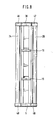
- FIG. 8 shows a view of the cabinet, with the doors 24, 26 arranged outside the housing according to the invention now being partially closed.
- the interior of the cabinet is at the bottom of the housing base 5 and the housing cover 36 at the top closed and contains two longitudinally spaced intermediate floors 19.
- the doors 24, 26 designed as rotating shells have the two bearing elements 46, 47 at the top in the area of the housing cover 36.
- the two bearing elements 48, 49 are provided at the bottom in the area of the housing base 5.
- the bearing elements 46 to 49 are arranged outside the housing and surround the housing cover 36 or housing base 5 and the housing walls.
Abstract
Description
Die Erfindung betrifft einen Schrank, insbesondere für Badezimmer und zur Aufnahme von Badeutensilien oder dergleichen, mit einem Gehäuse, welches eine gebogene Wand und einen Boden sowie einen Deckel aufweist, und mit einer um eine Drehachse angeordneten Tür zum Verschließen bzw. Freigeben einer Öffnung, welche zwischen zwei Längskanten des Gehäuses vorhanden ist.The invention relates to a cabinet, in particular for bathrooms and for receiving bathing utensils or the like, with a housing which has a curved wall and a floor and a lid, and with a door arranged around an axis of rotation for closing or uncovering an opening which is present between two longitudinal edges of the housing.
Schränke dieser Art sind in den unterschiedlichsten Ausgestaltungen bekannt und dienen beispielsweise in einem Badezimmer zum Aufbewahren und Bereithalten von Bade- bzw. Waschutensilien, Kosmetikas und sonstiger Dinge für die tägliche Körperpflege. Es sei hier beispielshaft auf sogenannte Spiegelschränke verwiesen, die an der Außenfläche ihrer Türen ebene Spiegel aufweisen. Ferner sind auch Kleinschränke, Regale oder ähnliches bekannt, die in einer Nische oder in einer Raumecke anzuordnen sind. Die bisher bekannten Schränke weisen relativ große Außenabmessungen auf, wobei ferner die Zugänglichkeit des Innenraumes des Gehäuses schwierig ist. Es ergeben sich Schwierigkeiten im Hinblick auf ein funktionsgerechte Einteilung und Ausnutzung des Innenraumes, zumal bei einer zu großen Tiefe die im hinteren Bereich befindlichen Teile nur schlecht zugänglich sind.Cupboards of this type are known in a wide variety of configurations and are used, for example, in a bathroom for storing and holding bath or washing utensils, cosmetics and other things for daily personal care. Reference is made here to so-called mirror cabinets, for example, which have flat mirrors on the outer surface of their doors. Small cabinets, shelves or the like are also known, which are to be arranged in a niche or in a corner of the room. The previously known cabinets have relatively large external dimensions, and it is also difficult to access the interior of the housing. Difficulties arise with regard to a functional division and utilization of the interior, especially since the parts located in the rear area are difficult to access if the depth is too great.
Aus der FR-PS 21 16 795 ist ein Schrank nachgewiesen, dessen Gehäusewand zylinderförmig ausgebildet ist. Der Gehäuseboden und der Gehäusedeckel enthalten Ringnuten, in welche die Gehäusewand mit ihrem unteren bzw. oberen Ende eingesetzt ist. Der Gehäuseboden und der Gehäusedeckel sind mittels einer zentralen Achse miteinander verbunden, die durch eine zentrale Bohrung im Boden hindurchgeführt ist, den gesamten Innenraum des Gehäuses durchdringt und oben in einer separaten Befestigungsvorrichtung mit dem Gehäusedeckel verbunden ist. Im Innenraum des Gehäuses befindet sich ein Karussell, das um die genannte Achse drehbar gelagert ist und zur Aufnahme von Flaschen dient. Zum Verschließen der Öffnung ist eine gebogene Tür vorhanden, welche in einander gegenüberliegenden Ringnuten vom Gehäuseboden und Gehäusedeckel angeordnet ist. Die Krümmungsradien der Tür und der Führungsnuten müssen exakt aufeinander abgestimmt sein und enge Fertigungstoleranzen müssen eingehalten werden. Das Gehäuse und die Tür müssen massiv ausgebildet sein, damit die schwenkbare Tür auch jederzeit bewegt werden kann; ein entsprechender Materialaufwand und ein entsprechendes Gewicht sind die Folge. Des weiteren kann durch Fremdkörper, die sich in den Führungsnuten festsetzen, die freie Schwenkbarkeit der Tür zumindest erschwert wenn nicht gar vollständig verhindert werden.From FR-
Der Erfindung liegt daher die Aufgabe zugrunde, einen Schrank zu schaffen, der bei einfacher und kostengünstiger Konstruktion eine gute Zugänglichkeit des Innenraumes und einen kompakten Aufbau aufweist. Der Schrank soll ein gefälliges Design aufweisen und bei geringem Gewicht eine gute Stabilität besitzen. Die Fertigung und Montage des Schrankes soll mit geringem Aufwand durchführbar sein, und eine funktionssichere Betätigung der Tür bzw. der Türen soll gewährleistet werden. Der Schrank soll problemlos im Eckbereich oder in einer Nische eines Raumes angeordnet werden können, wobei das Volumen des Aufhänge- oder Aufstellbereiches durch den Schrank weitgehend ausgenutzt wird, und somit letztendlich eine optimale Nutzung des zur Verfügung stehenden Raumes erfolgt.The invention is therefore based on the object of providing a cupboard which, with a simple and inexpensive construction, has good accessibility to the interior and a compact structure. The cabinet should have a pleasing design and have good stability with low weight. The manufacture and assembly of the cabinet should be carried out with little effort, and a reliable operation of the door or doors should be guaranteed. The cabinet should be able to be arranged in the corner area or in a niche of a room without any problems, whereby the volume of the hanging or installation area is largely used by the cabinet, and thus ultimately an optimal use of the available space.
Zur Lösung wird vorgeschlagen, daß eine zweite Tür um eine zweite Drehachse, die zur ersten Drehachse einen Abstand aufweist, drehbar angeordnet ist, daß die beiden gegeneinander schwenkbaren Türen jeweils am unteren und oberen Ende ein Lagerelement aufweisen und daß mittels Zapfen die Lagerelemente und die Türen im Gehäuseboden und Gehäusedeckel drehbar gelagert sind.To solve the problem, it is proposed that a second door is rotatably arranged about a second axis of rotation, which is at a distance from the first axis of rotation, that the two pivotable doors each have a bearing element at the lower and upper ends, and that the bearing elements and the doors are provided by means of pins are rotatably mounted in the housing base and housing cover.
Der erfindungsgemäße Schrank weist kompakte Außenabmessungen auf und ermöglicht eine optimale Nutzung des Innenraumes. Aufgrund der beiden gegeneinander schwenkbaren Türen, deren Drehachsen zueinander einen Abstand aufweisen, kann bei geringem Platz- und Gewichtsbedarf eine große Gehäuseöffnung funktionssicher verschlossen bzw. freigegeben werden. Durch die Lagerschalen wird mit geringem konstruktiven Aufwand eine funktionssichere Führung der Türen gewährleistet, ohne daß durch Verschmutzungen, Fremdkörper oder ähnliches eine Störung der Funktion zu erwarten ist. Die zueinander achsparallelen und insbesondere koaxialen Gehäuse-wände und Türen können ebenso wie der gesamte Schrank kostengünstig gefertigt werden und bestehen zweckmäßigerweise aus bogenförmigen Metallprofilen. Bevorzugt stellen die genannten Gehäusewände und Türen etwa viertelkreisförmige Schalen dar, wobei ggfs. jedoch auch vom Kreis abweichende Formen im Rahmen dieser Erfindung liegen. Wichtig ist die achsparallele Anordnung der Türschalen und der Gehäuseschalen derart, daß im geöffneten Zustand die sich praktisch über die gesamte Breite des Schrankes erstreckende Öffnung im wesentlichen vollständig freigegeben wird. Der Abstand der Vorderkanten der Gehäuseschalen ist erfindungsgemäß nur unwesentlich kleiner als die Gesamtbreite des Schrankes, so daß eine sehr gute Zugänglichkeit des Innenraumes und der in diesem angeordneten Zwischenböden, Haken oder ähnlichem gegeben ist. Entsprechend der gebogenen Ausgestaltung der Gehäuse- sowie Türschalen sind auch Zwischenböden, die erfindungsgemäß in Richtung der Längsachsen verstellbar sind, mit einer entsprechend gebogenen, angepaßten Kontur versehen. Diese Zwischenböden und ferner der Gehäusedeckel und der Gehäuseboden ragen teilweisen über die Öffnung bzw. die zwischen den beiden vorderen Längskanten der Gehäuseschalen sich erstreckende Ebene hinaus; die Zugänglichkeit des Innenraumes wird durch diese erfindungswesentliche Ausgestaltung erheblich erleichtert. Die Gehäuseschalen und auch die Türschalen können im Rahmen der Erfindung auch im wesentlichen gerade, und als Stege oder dergleichen ausgebildete Teile aufweisen, wobei jedoch durch entsprechende Anordnung der Längsachsen die erfindungsgemäße Schwenkbarkeit der Türschalen gewährleistet wird. Die gegeneinander verschwenkbaren Türschalen schließen im geschlossenen Zustand die Öffnung bzw. den gesamten Schrank vollständig ab, so daß bei Aufstellung im Badezimmer oder in einer Duschkabine das Eindringen von Spritzwasser weitgehend ausgeschlossen werden kann. Aufgrund der kompakten, praktisch allseits abgerundeten Außenkontur ist nicht nur ein formschönes Design gegeben, sondern darüberhinaus wird eine funktionsgerechte Anpassung und Integration bei optimaler Ausnutzung des zur Verfügung stehenden Raumes erreicht. Wesentlich ist ferner die vergleichsweise geringe Tiefe des Schrankes; mit anderen Worten, der Schrank ragt nicht allzu weit in das Badezimmer oder in einen sonstigen Aufstellraum hinein.The cabinet according to the invention has compact external dimensions and enables optimal use of the interior. Due to the two doors that can be pivoted relative to one another, the axes of rotation of which are spaced apart, a large housing opening can be closed or released in a functionally reliable manner with a small space and weight requirement. The bearing shells ensure reliable operation of the doors with little design effort, without a malfunction of the function being expected due to dirt, foreign bodies or the like. The housing walls and doors, which are axially parallel and in particular coaxial, as well as the entire cabinet, can be manufactured inexpensively and expediently consist of curved metal profiles. Preferably, the housing walls and doors mentioned are approximately quarter-circular shells, although shapes that deviate from the circle may also be within the scope of this invention. It is important to arrange the door shells and the housing shells parallel to the axis in such a way that in the open state the opening which extends practically over the entire width of the cabinet is essentially completely cleared. According to the invention, the distance between the front edges of the housing shells is only insignificantly smaller than the overall width of the cabinet, so that the interior and the intermediate floors, hooks or the like arranged in it are very easily accessible. Corresponding to the curved design of the housing and door shells, intermediate shelves, which according to the invention are adjustable in the direction of the longitudinal axes, are also provided with a correspondingly curved, adapted contour. These intermediate floors and also the housing cover and the housing base partially protrude beyond the opening or between the two front longitudinal edges of the housing shells extending level beyond; The accessibility of the interior is made considerably easier by this configuration which is essential to the invention. Within the scope of the invention, the housing shells and also the door shells can also be essentially straight and have parts designed as webs or the like, the pivotability of the door shells according to the invention being ensured, however, by appropriate arrangement of the longitudinal axes. The mutually pivotable door shells completely close the opening or the entire cupboard in the closed state, so that the penetration of splash water can be largely ruled out when installed in the bathroom or in a shower cubicle. Due to the compact, practically rounded outer contour, not only is there an elegant design, but moreover a functional adjustment and integration is achieved with optimal use of the available space. The comparatively small depth of the cabinet is also essential; in other words, the cabinet does not protrude too far into the bathroom or any other installation room.
In einer besonderen Ausgestaltung weist das Gehäuse an der Rückseite der Gehäuseschalen sich im wesentlichen jeweils über die gesamte Länge erstreckende Stege auf, die bevorzugt mittels eines Klemmprofiles miteinander verbunden sind. Ferner weisen die Gehäuseschalen und insbesondere die genannten Stege Schraubkanäle auf, welche die Befestigung eines Gehäusedeckels sowie eines Gehäusebodens am oberen bzw. unteren Ende mittels Schrauben oder dergleichen ermöglichen. Die Fertigung und Montage sind kostengünstig durchzuführen, zumal Gehäuseboden und Gehäusedeckel zweckmäßigerweise übereinstimmend ausgebildet sind. Die Gehäuseschalen bestehen zweckmäßig aus Metallprofilen und sind zwischen Gehäuseboden und Gehäusedeckel eingesetzt. Im Rahmen der Erfindung liegt aber auch die einstückige Ausbildung der beiden Gehäuseschalen samt Stegen oder dergleichen, und zwar bevorzugt aus einem Kunststoff, um in geeigneten Spritzformen gefertigt zu werden.In a special embodiment, the housing on the rear side of the housing shells has webs which essentially extend over the entire length and which are preferably connected to one another by means of a clamping profile. Furthermore, the housing shells and in particular the webs mentioned have screw channels which enable the fastening of a housing cover and a housing base at the upper or lower end by means of screws or the like. The manufacture and assembly can be carried out inexpensively, especially since the housing base and housing cover are expediently designed to match. The housing shells expediently consist of metal profiles and are inserted between the housing base and the housing cover. However, the one-piece construction of the two housing shells including webs or the like is also within the scope of the invention, preferably from a plastic, in order to be produced in suitable injection molds.
Im Rahmen dieser Erfindung erstrecken sich die Gehäuseschalen und auch die beiden Türschalen über Winkelbereiche größer als 90°, wobei sich Winkelbereiche in der Größenordnung von 110° als besonders zweckmäßig erwiesen haben. Die Gehäuseschalen bilden die Seitenwände und gleichzeitig einen Teil der Rückwand, welche durch die zwischen den Gehäuseschalen angeordnete Befestigungskonsole vervollständigt wird. Erfindungsgemäß ist die Breite der Befestigungskonsole näherungsweise gleich groß wie der Abstand der Längsachsen der beiden Gehäuseschalen. Der genannte Abstand ist in der Größenordnung von 20 % größer als der Radius der Gehäuseschalen. Aufgrund dieser Ausgestaltung ist im Bereich der Öffnung eine Einbuchtung vorhanden, in welche die beiden Türschalen mit ihren Vorderkanten hineinschwenken. Gleichwohl weist der Schrank einen etwa ovalen Grundriß auf, und eine vergleichsweise geringe Tiefe wird erreicht. Diese Einbuchtung an der Frontseite des Schrankes ergibt ein besonders gutes Design, doch kann im Rahmen dieser Erfindung dieser Bereich auch eben ausgebildet sein, um das nutzbare Innenvolumen zu vergrößern.In the context of this invention, the housing shells and also the two door shells extend over angular ranges greater than 90 °, with angular ranges on the order of 110 ° having proven particularly expedient. The housing shells form the side walls and at the same time form part of the rear wall, which is completed by the fastening bracket arranged between the housing shells. According to the invention, the width of the fastening bracket is approximately the same as the distance between the longitudinal axes of the two housing shells. The distance mentioned is on the order of 20% larger than the radius of the housing shells. Because of this configuration, there is an indentation in the area of the opening, into which the two door shells pivot with their front edges. Nevertheless, the cupboard has an approximately oval layout, and a comparatively small depth is achieved. This indentation on the front of the cabinet results in a particularly good design, but within the scope of this invention this area can also be designed to increase the usable internal volume.
In einer zweckmäßigen Ausgestaltung sind die Lagerelemente sektorähnlich ausgebildet über einen Zapfen oder dergleichen mit dem Gehäusedeckel bzw. dem Gehäuseboden in Eingriff stehen. Diese Lagerelemente sind als Abdeckkappe ausgebildet, um an den Enden, und zwar quer zu den Längsachsen, die Türschalen abzuschließen. Die Lagerelemente dienen erfindungsgemäß auch zur Stabilisierung und zur Abstützung der Türschalen, die somit mit einer vergleichsweise geringen Wandstärke ausgebildet sein können, wobei gleichwohl eine hohe Verwindungssteifigkeit und letztendlich eine leichtgängige Bewegung und Schwenkbarkeit der Türen bzw. der Türschalen auch über eine lange Lebensdauer gewährleistet wird. Die jeweilige Türschale ist in Ausnehmungen, Nuten oder ähnlichem in die zugeordnete Abdeckkappe eingesetzt, die aus einem gespritzten Kunststoff gefertigt ist. Die Lagerelemente oder Abdeckkappen weisen eine an die gebogene Kontur der Türschalen angepaßten Rand auf, der eine Auflagerung und Abstützung bildet und eine gute Stabilität und letztendlich eine Leichtgängigkeit gewährleistet.In an expedient embodiment, the bearing elements are configured in a sector-like manner and engage with the housing cover or the housing base via a pin or the like. These bearing elements are designed as a cover cap to close the door shells at the ends, specifically across the longitudinal axes. According to the invention, the bearing elements also serve to stabilize and to support the door shells, which can thus be formed with a comparatively small wall thickness, nevertheless ensuring high torsional rigidity and ultimately smooth movement and pivoting of the doors or door shells over a long service life. The respective door shell is inserted into recesses, grooves or the like in the associated cover cap, which is made of an injection molded plastic. The bearing elements or cover caps have an edge adapted to the curved contour of the door shells, which forms a support and support and ensures good stability and ultimately ease of movement.
In einer besonders zweckmäßigen Ausgestaltung sind den Türschalen und insbesondere den Lagerelementen miteinander in Eingriff stehende Zahnsegmete bzw. Verzahnungen zugeordnet. Aufgrund dieser Zahnsegmente wird die Betätigung und Handhabung nicht unwesentlich verbessert. Es genügt mit einer Hand die eine Türschale zu betätigen, um insgesamt die Öffnung des Schrankes freizugeben bzw. zu verschließen.In a particularly expedient embodiment, toothed segments or toothings which are in engagement with one another are assigned to the door shells and in particular the bearing elements. Due to these tooth segments, the actuation and handling is not insignificantly improved. It is sufficient to operate one door shell with one hand to open or close the opening of the cabinet.
Die Erfindung wird nachfolgend an Hand der in der Zeichnung dargestellten Ausführungsbeispiele näher erläutert. Es zeigen:
- Fig. 1 einen Schnitt quer zur Längsachse eines Schrankes mit zwei gegeneinander schwenkbaren Türen,
- Fig. 2 einen Schnitt parallel zur Längsachse durch den oberen Bereich des Schrankes,
- Fig. 3 eine Aufsicht auf den Gehäusedeckel in Blickrichtung III gemäß Fig. 2,
- Fig. 4 einen Schnitt entlang Linie IV gemäß Fig. 3,
- Fig. 5 eine Aufsicht auf ein Lagerelement samt Verzahnung in Blickrichtung III gemäß Fig. 2,
- Fig. 6 einen Schnitt entlang Linie VI gemäß Fig. 5,
- Fig. 7 eine perspektivische Ansicht des oberen Teiles des Schrankes,
- Fig. 8 eine Ansicht bei teilweise geschlossenen Türen.
- 1 shows a section transverse to the longitudinal axis of a cabinet with two doors that can be pivoted relative to one another,
- 2 shows a section parallel to the longitudinal axis through the upper region of the cabinet,
- 3 is a plan view of the housing cover in viewing direction III according to FIG. 2,
- 4 shows a section along line IV according to FIG. 3,
- 5 is a plan view of a bearing element including teeth in viewing direction III according to FIG. 2,
- 6 shows a section along line VI according to FIG. 5,
- 7 is a perspective view of the upper part of the cabinet,
- Fig. 8 is a view with partially closed doors.
Der Schnitt gemäß Fig. 1 zeigt zwei gebogene Gehäusewände 2, 4, welche im Bereich der Rückseite 6 des Schrankes Stege 7, 8 aufweisen, die ihrerseits mittels eines sich über die gesamte Länge erstreckenden Klemmprofiles 9 miteinander verbunden sind. Die Verbindung der Gehäusewände 2, 4 mit einem oberen Gehäusedeckel und einem unteren Gehäuseboden 5, welche übereinstimmend ausgebildet und zwischen welchen in Richtung der Achsen 10, 11 die beiden Gehäusewände 2, 4 angeordnet sind, erfolgt mittels Schrauben oder dergleichen, die in Schraubkanäle 13, 14 an der Außenseite der Stege 7, 8 von oben bzw. von unten eingreifen. Die beiden Gehäusewände 2, 4 sind bogenartig bzw. als Teile von Zylindern ausgebildet und erstrecken sind um die Achsen 10 bzw. 11 über einen Winkelbereich von näherungsweise 110°. Zwischen den vorderen Längskanten 15, 16 der beiden Gehäusewände 2, 4 befindet sich eine freie Öffnung 18, durch welche der Innenraum des Schrankes zugänglich ist. Die Achsen 10 und 11 weisen in einer zur Öffnung 18 parallelen Ebene einen Abstand 12 auf, der im wesentlichen gleich groß ist wie der Außenradius 17 der Türen 24, 26.1 shows two
Im Innenraum des Schrankes befinden sich in Richtung der Achsen 10, 11 beabstandet übereinander angeordnete Zwischenböden 19 bzw. hier nicht weiter dargestellte Haken, Trennwände oder dergleichen, die an der aus den Stegen 7, 8 gebildeten Befestigungskonsole befestigt sind. Hierzu weist diese in der Schrankmitte liegende Befestigungskonsole eine hinterschnittene Längsnut 20 auf, in welche die Zwischenböden oder dergleichen mit entsprechend ausgebildeten Halteteilen 21 eingesetzt sind. Aufgrund der erfindungsgemäßen Verbindung der Gehäuseschalen 2, 4 und insbesondere deren Stege 7, 8 mittels des Klemmprofiles 9 wird über die gesamte axiale Länge sichergestellt, daß die einander gegenüberliegenden Seitenwände dieser hinterschnittenen Längsnut 20 den gleichen Abstand aufweisen und nicht nach außen gedrückt werden können. Damit ist sichergestellt, daß die Halteteile 21 der Zwischenböden 19 Haken oder ähnliches auch bei Belastung sicher in der Längsnut 20 arretiert sind.In the interior of the cabinet, in the direction of the
Der gesamte Schrank und ebenfalls die im Inneren desselben angeordneten Böden weisen einen etwa ovalen Grundriß auf, wobei an der Vorderseite 23 im Bereich der Öffnung 18 vorn eine Einbuchtung 22 vorhanden ist. Der Abstand 12 zwischen den beiden Drehachsen 10, 11 entspricht im wesentlichen dem äuße ren Radius der Gehäuseschalen 2, 4 und ist zweckmäßigerweise in der Größenordnung von 20% größer als dieser Radius. Die Tiefe, also der Abstand zwischen der Einbuchtung 22 und der Befestigungskonsole, ist folglich vergleichsweise klein und insgesamt wird trotz abgerundeter Gehäuseschalen ein schmaler Grundriß erreicht. Die Einbuchtung 22 ergibt sich somit aufgrund der erfindungsgemäßen koaxialen Anordnung der Gehäuseschalen und der Türen 24, 26 sowie deren im wesentlichen kreisbogenförmigen oder tonnenartigen Ausbildung. Selbstverständlich liegen im Rahmen dieser Erfindung auch solche Ausführungsformen, die auch an der Vorderseite 23, ähnlich wie an der Rückseite 6, im wesentlichen eben ausgebildet sind. Wesentlich ist bei allen Ausführungsformen, daß die vorderen Längskanten 15, 16 der Gehäuseschalen 2, 4 von der Frontfläche oder der Vorderseite 23 zur Rückseite hin zurückversetzt sind. Sind die Türen bzw. Drehschalen 24, 26 in Richtung der Pfeile 17 nach hinten geschwenkt, so ist der Innenraum des Schrankes sehr gut zugänglich, und zwar praktisch teilweise auch von der Seite her.The entire cabinet and also the shelves arranged in the interior thereof have an approximately oval plan, an
Koaxial zu den Gehäuseschalen 2, 4 sind um die Drehachsen 10, 11 die Türen 24, 26 angeordnet. Die Türen 24, 26 sind erfindungsgemäß außen um die Gehäuseschalen 2, 4 mit einem relativ geringen Abstand angeordnet und erstrecken sich ebenfalls über einen Winkelbereich größer 90° und zwar zweckmäßigerweise etwa 110°. Werden die Türen 24, 26 aus der dargestellten Position in Richtung der Pfeile 27 um die Achsen 10, 12 von der Öffnung 18 weggeschwenkt, so wird diese geöffnet. Die Türen 24, 26 sind ebenso wie die beiden Gehäuseschalen 2, 4 erfindungsgemäß als dünnwandige Metallprofile ausgebildet, die entsprechend der Höhe bzw. Länge des Schrankes auf die erforderliche Länge gebracht sind. Die Gesamtlänge des Schrankes ist somit im Rahmen dieser Erfindung problemlos vorgebbar. Die Türen 24, 26 weisen im Bereich ihrer Vorderkanten 28 und ihrer Hinterkanten 30 nach außen vorstehende Rippen 34 auf, die ein Benutzer zum Öffnen oder Schließen des Schrankes in einfacher Weise ergreifen kann. Obgleich die koaxiale Anordnung besonders zweckmäßig ist, können im Rahmen dieser Erfindung die Drehachsen der Türen von denen der Gehäuseschalen beabstandet angeordnet sein; dies ist insbesondere bei einer Ausbildung der Drehschalen abweichend von der dargestellten kreisförmigen Außenkontur zweckmäßig.The
So können beispielsweise die im Bereich der Einbuchtung 22 befindlichen und zur Rückseite gebogenen Teile auch eben ausgebildet sein, um eine praktische ebene Frontfläche in diesem Bereich zu erhalten. Zweckmäßig werden dann unter Beachtung der Krümmungsradien die Drehachsen 10, 11 der Türschalen bezüglich den Längsachsen der Gehäuseschalen versetzt. An der Rückseite 6 befindet sich ein Wandanschlußelement 29, das an einer ebenen Raumwand angeschraubt werden kann. Zur Montage in einer Ecke eines Badezimmers oder dergleichen kann das Wandanschlußelement auch die strichpunktiert angedeutete Form aufweisen. Dem Wandanschlußelement 29 ist oben und unten ein Bügel mit einem nachfolgend noch zu erläuternden Arm zugeordnet, um eine einfache Verbindung und Montage des gesamten Schrankes an der derart ausgebildeten Befestigungskonsole zu ermöglichen. Die Drehschalen 24, 26 sind wie nachfolgend noch erläutert wird, mittels Zapfen 31 im Gehäuseboden 5 und entsprechend im Gehäusedeckel schwenkbar befestigt, wobei mittels eines Clips oder eines Sicherungsringes 33, der in eine Ringnut eines Zapfens 31 eingreift, die axiale Sicherung erreicht wird.For example, the parts located in the region of the
Fig. 2 zeigt einen Schnitt durch die Ebene der Achsen 10, 11 im oberen Bereich des Schrankes, wobei hier der obere Gehäusedeckel 36 zu erkennen ist. In entsprechender Weise ist am unteren Ende des Schrankes ein gleich ausgebildeter Gehäuseboden vorgesehen, so daß nachstehende Erläuterungen entsprechend gelten. Der Gehäusedeckel 36 weist einen Außenrand 38 auf, an welchem die Gehäuseschalen 2, 4 mit ihrem oberen Ende erfindungsgemäß anliegen. Der Gehäusedeckel 36 enthält eine vom Außenrand 38 begrenzte Stützfläche 40, an welcher die beiden Gehäuseschalen 2, 4 mit ihren axialen Endflächen erfindungsgemäß anliegen. Wie oben bereits angegeben, sind der Gehäusedeckel 36 und der Gehäuseboden mittels Schrauben, die in die Schraubkanäle der Stege eingreifen verbunden, wobei zwischen Gehäusedeckel und Gehäuseboden in der dargestellten Weise die beiden Gehäuseschalen 2, 4 eingespannt sind. Die Montage des Schrankes ist damit äußerst einfach, da nach dem entsprechenden Zusammenfügen lediglich die Schraubverbindung zwischen Gehäusedecket bzw. Gehäuseboden und Befestigungskonsole herzustellen ist.Fig. 2 shows a section through the plane of the
Die Türen 24, 26 werden oben mittels je eines als Abdeckkappe ausgebildeten Lagerelementes 46, 47 abgeschlossen, welche sich über den Gehäusedeckel 36 hinweg erstrecken und mittels den Zapfen 32 schwenkbar bezüglich des Gehäusedeckels 36 sind. Diese Zapfen 32 befinden sich in oben erweiterten Bohrungen 50, 51 und durchdringen den Gehäusedeckel 36 und sind unterhalb desselben mittels den Sicherungsringen 33 abgefangen und gegen axiales Verschieben gesichert. Für die am unteren Ende des Schrankes übereinstimmend ausgebildeten Lagerelemente gelten diese Erklärungen entsprechend. Die Abdeckkappen bzw. Lagerelemente 46, 47 weisen im Bereich ihres Außenrandes 54, 56 erfindungsgemäß jeweils eine Ringnut 58, 60 auf, in welche die Türschalen 24, 26 mit ihren oberen Enden eingesetzt sind. Die Lagerelemente 46, 47 sind ebenso wie die beiden Türschalen 24, 26 außerhalb der feststehenden Teile des Schrankes, also außerhalb vom Gehäusedeckel 36 sowie der Gehäusewände 2, 4, angeordnet und um diese herum bezüglich der beiden beabstandeten Drehachsen 10, 11 schwenkbar. Schließlich ist über den beiden Lagerelemente 46, 47 ein übergreifender Abschlußdeckel 62 angeordnet, um einerseits eine einfache Reinigungsmöglichkeit und andererseits Funktionsstörungen oder eine Verschmutzung der gegeneinander bewegbaren Teile zu unterbinden.The
Fig. 3 zeigt eine Aufsicht auf den oberen Gehäusedeckel 36, wobei nunmehr auch die Auflagefläche 64 für den oben erwähnten Arm des Wandanschlußelements der Befestigungskonsole zu erkennen ist. Mittels Zapfen 66, Nuten oder ähnlichem greifen die hinteren Stege und der Gehäusedeckel 36 erfindungsgemäß ineinander, wodurch eine gute gegenseitige Ausrichtung und Fixierung erreicht wird. Es sind hier auch zwei Bohrungen 67 zu erkennen, welche mit den oben erwähnten Schraubkanälen der Stege fluchten. Durch diese Bohrungen 67 werden zur Verbindung von Gehäusedekkel und Gehäuseschalen Schrauben eingeschraubt. Ferner befinden sich erfindungsgemäß koaxial zu den Achsen in der Außenfläche des Gehäusedeckels 36 Ringnuten 68 für nachfolgend noch zu erläuternde Zahnsegmente.Fig. 3 shows a plan view of the
Fig. 4 zeigt einen Schnitt entlang Linie IV von Fig. 3, wobei nunmehr auch die in die Oberfläche des Gehäusedeckels 36 eingebrachten Ringnuten 68 gut zu erkennen sind. Die Sackbohrung 69 dient zur Aufnahme einer Schraube, welche durch den auf der Auflagefläche 64 aufliegenden Arm der Befestigungskonsole bzw. des Wandanschlußelements hindurchgeführt ist, wodurch eine einfache Befestigung und Montage des Schrankes an einer Wand oder dergleichen ermöglicht wird. Übereinstimmend ist der Gehäuseboden ausgebildet.FIG. 4 shows a section along line IV of FIG. 3, the
Fig. 5 zeigt eine Aufsicht auf das Lagerelement 46 mit einer sektorartigen Verzahnung 70. Auch das andere Lagerelement weist eine entsprechend ausgebildete Verzahnung auf, wobei beide Verzahnungen ineinandergreifen. Diese Verzahnungen 70 reichen in die oben genannten Ringnuten 68 und stehen im Bereich der Verbindungslinie zwischen den beiden Längsachsen miteinander in Eingriff. Aufgrund der Anordnung der Verzahnungen 70 in den Ringnuten sind jene nach außen praktisch nicht sichtbar, wobei ferner die Gefahr einer Verschmutzung oder das Eindringen von Fremdkörpern nicht unwesentlich verringert wird. Mittels der Verzahnungen 70 wird die gegenläufige Bewegung der beiden Lagerelemente 46, 47 und der Türschalen und letztendlich eine einfache Handhabung beim Öffnen bzw. schließen des Schrankes gewährleistet. Die Verzahnungen 70 befinden sich an etwa halbkreisförmigen Ansätzen der Lagerelemente bzw. der Abdeckkappen und erstrecken sich über Winkelbereiche in der Größenordnung von etwa 110 bis 130 Winkelgraden. Es ist gewährleistet, daß für den gesamten Weg der Schwenkbewegung der Eingriff aufrechterhalten wird und die gemeinsame Betätigung erfolgen kann.5 shows a top view of the bearing
Zumindest an dem einen Lagerelement 46 bzw. dessen Ansatz 74 ist bevorzugt an einem kleinen Stift 78 ein Federlement 80 befestigt, dessen anderes Ende am Gehäusedeckel oder am andereren Lagerelement befestigt ist. Erfindungsgemäß ist das Federelement, welches auch als ein einfacher Gummiring ausgebildet sein kann, derart angeordnet, daß eine Schnappmechanik vorliegt, um die Türschalen wahlweise in die Schließ- oder Offenstellung zu bringen. Das Lagerelement 46 ist hier in der Offenstellung des Schrankes dargestellt und nimmt die zur Rückseite des Schrankes geschwenkte Stellung ein. Wird das Führungselement 46 und die Drehschalen in Richtung des Pfeiles 82 nach vorn geschwenkt, so überschreitet der Stift 78 den Kippunkt, der durch die Verbindungslinie der beiden Längsachsen definiert ist, und nachfolgend wird das Führungselement 46 durch das vorgespannte Federelement 80 in die Schließstellung gebracht. Das Federelement ist in entsprechender Weise an einem Stift des zugeordneten Lagerelements befestigt.At least on one
Fig. 6 zeigt einen Schnitt durch die Abdeckkappe 46, wobei hier deutlich die abgesetzte Bohrung 50 für den Befestigungszapfen sowie das nach unten gerichtete Zahnsegment 70 zu erkennen ist. In die Ringnut 58 greift die axiale Stirnfläche der Türschale und ist dort im Rahmen dieser Erfindung funktionsgerecht abgestützt und arretiert. An der Innenfläche 84 vom Rand 54 liegt die hier nicht dargestellte Türschale an und wird funktionssicher abgestützt. Die Innenfläche 84 weist einen Radius auf, der mit dem Außenradius 17 der Türschale übereinstimmt.FIG. 6 shows a section through the
In Fig. 7 ist eine perspektivische Ansichts des oberen Teiles des Schrankes dargestellt, wobei die Türen 24, 26 geöffnet sind und die Öffnung zwischen den vorderen Längskanten der beiden Wandteile 2, 4 freigegeben ist. Die oberen Lagerelemente 46, 47 sowie die Zapfen 32 sind gut zu erkennen. Der Zwischenboden 19 ist mit dem Halteteil 21 in der Längsnut 20 an der Rückseite des Schrankes befestigt. Der Arm 86 des Wandanschlußelementes ist mittels einer Schraube 88 mit dem Gehäusedeckel 36 verbunden.7 shows a perspective view of the upper part of the cabinet, the
Fig. 8 zeigt eine Ansicht des Schrankes, wobei nunmehr die erfindungsgemäß außerhalb des Gehäuses angeordneten Türen 24, 26 teilweise geschlossen sind. Der Innenraum des Schrankes wird unten vom Gehäuseboden 5 und oben vom Gehäusedeckel 36 abgeschlossen und enthält zwei in Längsrichtung beabstandete Zwischenböden 19. Die als Drehschalen ausgebildeten Türen 24, 26 weisen oben im Bereich des Gehäusedeckels 36 die beiden Lagerelemente 46, 47 auf. Entsprechend sind unten im Bereich des Gehäusebodens 5 die beiden Lagerelemente 48, 49 vorgesehen. Die Lagerelemente 46 bis 49 sind im Rahmen dieser Erfindung außerhalb des Gehäuses angeordnet und umgeben den Gehäusedeckel 36 bzw. Gehäuseboden 5 sowie die Gehäusewände.8 shows a view of the cabinet, with the
- 2, 4 Gehäusewand2, 4 housing wall
- 5 Gehäuseboden5 case back
- 6 Rückseite6 back
- 7, 8 Steg7, 8 bridge
- 9 Klemmprofil9 clamping profile
- 10, 11 Drehachse10, 11 axis of rotation
- 12 Abstand12 distance
- 13, 14 Schraubkanal13, 14 screw channel
- 15, 16 vordere Längskante15, 16 front longitudinal edge
- 17 Außenradius von 24, 2617 outer radius of 24, 26
- 18 Öffnung18 opening
- 19 Zwischenboden19 mezzanine
- 20 Längsnut in 820 longitudinal groove in 8
- 21 Halteteil21 holding part
- 22 Einbuchtung22 indentation
- 23 Vorderseite23 front
- 24, 26 Tür24, 26 door
- 27 Pfeil27 arrow
- 28 Vorderkante28 leading edge
- 29 Wandanschlußelement29 wall connection element
- 30 Hinterkante30 rear edge
- 31, 32 Zapfen31, 32 cones
- 33 Sicherungsring33 circlip
- 34 Rippe34 rib
- 36 Gehäusedeckel36 housing cover
- 38 Außenrand38 outer edge
- 40 Stützfläche40 support surface
- 46 bis 49 Lagerelement46 to 49 bearing element
- 50, 51 Bohrung50, 51 bore
- 54, 56 Rand54, 56 margin
- 58, 60 Ringnut58, 60 ring groove
- 62 Abschlußdeckel62 end cover
- 64 Auflagefläche64 contact surface
- 66 Zapfen66 cones
- 67 Bohrung67 hole
- 68 Ringnut68 ring groove
- 69 Sackbohrung69 blind hole
- 70, 72 Verzahnung70, 72 toothing
- 74, 76 Ansatz74, 76 approach
- 78 Stift78 pen
- 80 Federelement80 spring element
- 82 Pfeil82 arrow
- 84 Innenfläche84 inner surface
- 86 Arm86 arm
- 88 Schraube88 screw
Claims (10)
dadurch gekennzeichnet, daß eine zweite Tür (26) um eine zweite Drehachse (11), die zur ersten Drehachse (10) einen Abstand (12) aufweist, drehbar angeordnet ist, daß die beiden gegeneinander schwenkbaren Türen (24, 26) jeweils am unteren und oberen Ende ein Lagerelement (46 bis 49) aufweisen, und daß mittels Zapfen (31, 32) die Lagerelemente (46 bis 49) und die Türen (24, 26) im Gehäuseboden (5) und Gehäusedeckel (36) drehbar gelagert sind.1. Cabinet, in particular for bathrooms and to accommodate bathing utensils or the like with a housing which has a curved wall (2) and a bottom (5) and a cover (36), and with a rotatable about an axis of rotation (10) Door (24) for closing or opening an opening (18) which is present between two longitudinal edges (15, 16) of the housing,
characterized in that a second door (26) is arranged so as to be rotatable about a second axis of rotation (11) which is at a distance (12) from the first axis of rotation (10), that the two doors (24, 26) which can be pivoted relative to one another are each at the bottom and the upper end have a bearing element (46 to 49), and in that the bearing elements (46 to 49) and the doors (24, 26) in the housing base (5) and housing cover (36) are rotatably mounted by means of pins (31, 32).
Priority Applications (1)
| Application Number | Priority Date | Filing Date | Title |
|---|---|---|---|
| AT87100218T ATE66279T1 (en) | 1986-01-21 | 1987-01-09 | CLOSET, ESPECIALLY FOR BATHROOMS. |
Applications Claiming Priority (2)
| Application Number | Priority Date | Filing Date | Title |
|---|---|---|---|
| DE19863601614 DE3601614A1 (en) | 1986-01-21 | 1986-01-21 | CABINET, ESPECIALLY FOR BATHROOMS |
| DE3601614 | 1986-01-21 |
Publications (3)
| Publication Number | Publication Date |
|---|---|
| EP0230237A2 true EP0230237A2 (en) | 1987-07-29 |
| EP0230237A3 EP0230237A3 (en) | 1988-07-20 |
| EP0230237B1 EP0230237B1 (en) | 1991-08-14 |
Family
ID=6292268
Family Applications (1)
| Application Number | Title | Priority Date | Filing Date |
|---|---|---|---|
| EP87100218A Expired - Lifetime EP0230237B1 (en) | 1986-01-21 | 1987-01-09 | Cabinet, especially adapted to bathrooms |
Country Status (8)
| Country | Link |
|---|---|
| US (1) | US4783132A (en) |
| EP (1) | EP0230237B1 (en) |
| AT (1) | ATE66279T1 (en) |
| AU (1) | AU592273B2 (en) |
| CA (1) | CA1317627C (en) |
| DE (2) | DE3601614A1 (en) |
| GR (1) | GR3002719T3 (en) |
| ZA (1) | ZA87360B (en) |
Cited By (1)
| Publication number | Priority date | Publication date | Assignee | Title |
|---|---|---|---|---|
| EP0577355A1 (en) * | 1992-07-01 | 1994-01-05 | Aqualux Products Limited | Cupboards |
Families Citing this family (8)
| Publication number | Priority date | Publication date | Assignee | Title |
|---|---|---|---|---|
| FR2602410B1 (en) * | 1986-08-11 | 1989-03-10 | Secretariat Etat Premier Minis | STORAGE LOCKER, ESPECIALLY FOR SPORTS FACILITIES, LOCKER SET, RACK OF LOCKERS AND LOCKER ROOM EQUIPPED WITH SUCH LOCKERS |
| US5458407A (en) * | 1993-04-14 | 1995-10-17 | L&P Property Management Company | Merchandising display |
| FI946052A (en) * | 1994-12-23 | 1996-06-24 | Ido Kylpyhuone Oy | lockers |
| JP3097492B2 (en) | 1995-04-17 | 2000-10-10 | 住友電気工業株式会社 | Laser light source and its manufacturing method |
| US5866876A (en) * | 1997-01-02 | 1999-02-02 | Su; Johnson | Electric oven |
| DE29711659U1 (en) * | 1997-07-03 | 1997-11-13 | Neuland Gmbh Kommunikation | Serving trolley |
| GB2353463A (en) * | 1999-08-25 | 2001-02-28 | Berlinlondon Ltd | Locker arrangement |
| US20050016081A1 (en) * | 2003-05-30 | 2005-01-27 | Gomree Jean Francois | Workspace habitat |
Citations (6)
| Publication number | Priority date | Publication date | Assignee | Title |
|---|---|---|---|---|
| DE160737C (en) * | ||||
| FR948420A (en) * | 1947-06-09 | 1949-08-01 | Pivot door for metal furniture | |
| GB693446A (en) * | 1950-08-30 | 1953-07-01 | Harry Woolf | Improvements in or relating to wardrobes and like cabinets |
| US3692376A (en) * | 1970-12-17 | 1972-09-19 | Double Sixteen Co | Case for recording tape cassettes |
| DE2137914A1 (en) * | 1971-07-23 | 1973-02-15 | Bade Dieter E Dipl Ing | CLOSURE FOR SMALL BUILDING |
| EP0027667A2 (en) * | 1979-10-17 | 1981-04-29 | Christophe Gevers | Furniture element, in particular storing cabinet, and storing unit composed of such a furniture element |
Family Cites Families (13)
| Publication number | Priority date | Publication date | Assignee | Title |
|---|---|---|---|---|
| US1033711A (en) * | 1907-03-02 | 1912-07-23 | Mfg Equipment & Engineering Company | Locker. |
| US892222A (en) * | 1907-09-09 | 1908-06-30 | John Hugh Arber | Mechanism for opening and closing doors. |
| US1702178A (en) * | 1927-12-02 | 1929-02-12 | El Paso Sash & Door Co | Telephone cabinet |
| US1934929A (en) * | 1931-03-28 | 1933-11-14 | Jonsson Arvas & Co | Transport wagons, especially for railways |
| US1874562A (en) * | 1931-05-01 | 1932-08-30 | Daprato Statuary Company | Door operating mechanism |
| US2507342A (en) * | 1947-04-30 | 1950-05-09 | Licari Vincent | Toothbrush holder |
| FR2116795A5 (en) * | 1970-12-08 | 1972-07-21 | Mazzoleni Freres | |
| US3730468A (en) * | 1971-12-20 | 1973-05-01 | Gypsum Co | Furniture supporting system |
| US3976344A (en) * | 1972-02-11 | 1976-08-24 | Georges Frydman | Assembly system for furniture panels |
| US3826207A (en) * | 1972-08-21 | 1974-07-30 | Pickering Ind Inc | Collapsible, adjustable shelving |
| US4288132A (en) * | 1980-02-19 | 1981-09-08 | Roper Corporation | Metal cabinet for assembly by the user from knocked-down condition |
| US4621877A (en) * | 1984-08-01 | 1986-11-11 | Digital Equipment Corporation | Securing cabinet walls |
| DE8506281U1 (en) * | 1985-03-05 | 1985-05-30 | Ninkaplast Gmbh, 4902 Bad Salzuflen | ROTATABLE SHELVING INSERT FOR CORNER CABINETS |
-
1986
- 1986-01-21 DE DE19863601614 patent/DE3601614A1/en active Granted
-
1987
- 1987-01-09 AT AT87100218T patent/ATE66279T1/en active
- 1987-01-09 DE DE8787100218T patent/DE3772060D1/en not_active Expired - Fee Related
- 1987-01-09 EP EP87100218A patent/EP0230237B1/en not_active Expired - Lifetime
- 1987-01-14 CA CA000527351A patent/CA1317627C/en not_active Expired - Fee Related
- 1987-01-19 ZA ZA87360A patent/ZA87360B/en unknown
- 1987-01-21 US US07/005,869 patent/US4783132A/en not_active Expired - Fee Related
- 1987-01-21 AU AU67892/87A patent/AU592273B2/en not_active Ceased
-
1991
- 1991-09-12 GR GR91401324T patent/GR3002719T3/en unknown
Patent Citations (6)
| Publication number | Priority date | Publication date | Assignee | Title |
|---|---|---|---|---|
| DE160737C (en) * | ||||
| FR948420A (en) * | 1947-06-09 | 1949-08-01 | Pivot door for metal furniture | |
| GB693446A (en) * | 1950-08-30 | 1953-07-01 | Harry Woolf | Improvements in or relating to wardrobes and like cabinets |
| US3692376A (en) * | 1970-12-17 | 1972-09-19 | Double Sixteen Co | Case for recording tape cassettes |
| DE2137914A1 (en) * | 1971-07-23 | 1973-02-15 | Bade Dieter E Dipl Ing | CLOSURE FOR SMALL BUILDING |
| EP0027667A2 (en) * | 1979-10-17 | 1981-04-29 | Christophe Gevers | Furniture element, in particular storing cabinet, and storing unit composed of such a furniture element |
Cited By (1)
| Publication number | Priority date | Publication date | Assignee | Title |
|---|---|---|---|---|
| EP0577355A1 (en) * | 1992-07-01 | 1994-01-05 | Aqualux Products Limited | Cupboards |
Also Published As
| Publication number | Publication date |
|---|---|
| ZA87360B (en) | 1987-09-30 |
| DE3601614C2 (en) | 1988-01-14 |
| GR3002719T3 (en) | 1993-01-25 |
| EP0230237A3 (en) | 1988-07-20 |
| EP0230237B1 (en) | 1991-08-14 |
| US4783132A (en) | 1988-11-08 |
| CA1317627C (en) | 1993-05-11 |
| AU592273B2 (en) | 1990-01-04 |
| DE3772060D1 (en) | 1991-09-19 |
| AU6789287A (en) | 1987-07-23 |
| ATE66279T1 (en) | 1991-08-15 |
| DE3601614A1 (en) | 1987-07-23 |
Similar Documents
| Publication | Publication Date | Title |
|---|---|---|
| DE202004000652U1 (en) | hinge | |
| AT401667B (en) | FURNITURE HINGE WITH LOCKING MECHANISM | |
| EP0384224B1 (en) | Guiding device | |
| EP0589170A1 (en) | Actuating rod fitting for windows, doors and the like | |
| EP0230237A2 (en) | Cabinet, especially adapted to bathrooms | |
| DE102008049740B4 (en) | Height adjustable band | |
| EP1946686B1 (en) | Partition wall, in particular shower partition wall | |
| EP1497521A1 (en) | Arrangement for fixing furniture fittings to frame profiles of plate-type or board-type furniture elements | |
| EP0536471B1 (en) | Mounting plate for furniture hinges | |
| EP0237789B1 (en) | Door hinge allowing a 180 degrees opening | |
| EP3880918A1 (en) | Furniture hinge | |
| DE3248260A1 (en) | Hinge and its use for the fastening of lavatory lids and/or seats | |
| DE3807729C2 (en) | Furniture hinge | |
| DE2648095C2 (en) | hinge | |
| DE19510941A1 (en) | Wall holder for sanitary fittings | |
| EP1306505A2 (en) | Hinge, especially for doors of vehicles | |
| DE3223590C2 (en) | ||
| EP1283319B1 (en) | Partition wall | |
| AT503457B1 (en) | HINGE FOR SWIVELING FLAP OR DOOR WINGS IN THE BASKET OF FURNITURE PIECES | |
| DE1559815C3 (en) | Furniture hinge | |
| DE2911875A1 (en) | HANGING DEVICE FOR A SLIDING WALL PANEL OF A SLIDING PARTITION | |
| DE3343903A1 (en) | WIDE ANGLE HINGE | |
| EP1876319B1 (en) | Sliding guide for sliding wings or wings movable into a parallel plane | |
| DE2647776C2 (en) | hinge | |
| DE2736962A1 (en) | Furniture hinge with adjustable hinge pin - has rack and pinion mechanism to slide pin longitudinally |
Legal Events
| Date | Code | Title | Description |
|---|---|---|---|
| PUAI | Public reference made under article 153(3) epc to a published international application that has entered the european phase |
Free format text: ORIGINAL CODE: 0009012 |
|
| 17P | Request for examination filed |
Effective date: 19870109 |
|
| AK | Designated contracting states |
Kind code of ref document: A2 Designated state(s): AT BE CH DE ES FR GB GR IT LI NL SE |
|
| PUAL | Search report despatched |
Free format text: ORIGINAL CODE: 0009013 |
|
| AK | Designated contracting states |
Kind code of ref document: A3 Designated state(s): AT BE CH DE ES FR GB GR IT LI NL SE |
|
| RAP1 | Party data changed (applicant data changed or rights of an application transferred) |
Owner name: B.V. LEIDSE HOUTHANDEL V/H KATER EN WIETHOFF |
|
| RIN1 | Information on inventor provided before grant (corrected) |
Inventor name: BAUS, HEINZ GEORG |
|
| 17Q | First examination report despatched |
Effective date: 19890908 |
|
| RAP1 | Party data changed (applicant data changed or rights of an application transferred) |
Owner name: ALTURA LEIDEN HOLDING B.V. |
|
| RAP1 | Party data changed (applicant data changed or rights of an application transferred) |
Owner name: DUSCHOLUX GMBH Owner name: ALTURA LEIDEN HOLDING B.V. |
|
| RIN1 | Information on inventor provided before grant (corrected) | ||
| GRAA | (expected) grant |
Free format text: ORIGINAL CODE: 0009210 |
|
| AK | Designated contracting states |
Kind code of ref document: B1 Designated state(s): AT BE CH DE ES FR GB GR IT LI NL SE |
|
| PG25 | Lapsed in a contracting state [announced via postgrant information from national office to epo] |
Ref country code: GR Free format text: LAPSE BECAUSE OF FAILURE TO SUBMIT A TRANSLATION OF THE DESCRIPTION OR TO PAY THE FEE WITHIN THE PRESCRIBED TIME-LIMIT Effective date: 19910814 |
|
| REF | Corresponds to: |
Ref document number: 66279 Country of ref document: AT Date of ref document: 19910815 Kind code of ref document: T |
|
| ET | Fr: translation filed | ||
| REF | Corresponds to: |
Ref document number: 3772060 Country of ref document: DE Date of ref document: 19910919 |
|
| ITF | It: translation for a ep patent filed |
Owner name: ING. PIOVESANA PAOLO |
|
| PG25 | Lapsed in a contracting state [announced via postgrant information from national office to epo] |
Ref country code: ES Free format text: LAPSE BECAUSE OF FAILURE TO SUBMIT A TRANSLATION OF THE DESCRIPTION OR TO PAY THE FEE WITHIN THE PRESCRIBED TIME-LIMIT Effective date: 19911125 |
|
| GBT | Gb: translation of ep patent filed (gb section 77(6)(a)/1977) | ||
| PG25 | Lapsed in a contracting state [announced via postgrant information from national office to epo] |
Ref country code: SE Effective date: 19920110 |
|
| PG25 | Lapsed in a contracting state [announced via postgrant information from national office to epo] |
Ref country code: BE Effective date: 19920131 |
|
| PLBE | No opposition filed within time limit |
Free format text: ORIGINAL CODE: 0009261 |
|
| STAA | Information on the status of an ep patent application or granted ep patent |
Free format text: STATUS: NO OPPOSITION FILED WITHIN TIME LIMIT |
|
| BERE | Be: lapsed |
Owner name: ALTURA LEIDEN HOLDING B.V. Effective date: 19920131 |
|
| PG25 | Lapsed in a contracting state [announced via postgrant information from national office to epo] |
Ref country code: NL Effective date: 19920801 |
|
| 26N | No opposition filed | ||
| NLV4 | Nl: lapsed or anulled due to non-payment of the annual fee | ||
| REG | Reference to a national code |
Ref country code: GR Ref legal event code: FG4A Free format text: 3002719 |
|
| REG | Reference to a national code |
Ref country code: GR Ref legal event code: MM2A Free format text: 3002719 |
|
| EUG | Se: european patent has lapsed |
Ref document number: 87100218.4 Effective date: 19920806 |
|
| PGFP | Annual fee paid to national office [announced via postgrant information from national office to epo] |
Ref country code: DE Payment date: 19980313 Year of fee payment: 12 |
|
| PG25 | Lapsed in a contracting state [announced via postgrant information from national office to epo] |
Ref country code: DE Free format text: LAPSE BECAUSE OF NON-PAYMENT OF DUE FEES Effective date: 19991103 |
|
| PGFP | Annual fee paid to national office [announced via postgrant information from national office to epo] |
Ref country code: FR Payment date: 20000118 Year of fee payment: 14 |
|
| PGFP | Annual fee paid to national office [announced via postgrant information from national office to epo] |
Ref country code: AT Payment date: 20000120 Year of fee payment: 14 |
|
| PG25 | Lapsed in a contracting state [announced via postgrant information from national office to epo] |
Ref country code: AT Free format text: LAPSE BECAUSE OF NON-PAYMENT OF DUE FEES Effective date: 20010109 |
|
| PG25 | Lapsed in a contracting state [announced via postgrant information from national office to epo] |
Ref country code: FR Free format text: LAPSE BECAUSE OF NON-PAYMENT OF DUE FEES Effective date: 20010928 |
|
| REG | Reference to a national code |
Ref country code: FR Ref legal event code: ST |
|
| REG | Reference to a national code |
Ref country code: GB Ref legal event code: IF02 |
|
| REG | Reference to a national code |
Ref country code: CH Ref legal event code: PFA Owner name: ALTURA LEIDEN HOLDING B.V. Free format text: ALTURA LEIDEN HOLDING B.V.#WILHELMINASINGEL 118#MAASTRICHT (NL) -TRANSFER TO- ALTURA LEIDEN HOLDING B.V.#WILHELMINASINGEL 111#6221 BJ MAASTRICHT (NL) |
|
| PG25 | Lapsed in a contracting state [announced via postgrant information from national office to epo] |
Ref country code: IT Free format text: LAPSE BECAUSE OF NON-PAYMENT OF DUE FEES Effective date: 20050109 |
|
| PGFP | Annual fee paid to national office [announced via postgrant information from national office to epo] |
Ref country code: GB Payment date: 20060123 Year of fee payment: 20 |
|
| PGFP | Annual fee paid to national office [announced via postgrant information from national office to epo] |
Ref country code: CH Payment date: 20060124 Year of fee payment: 20 |
|
| PG25 | Lapsed in a contracting state [announced via postgrant information from national office to epo] |
Ref country code: GB Free format text: LAPSE BECAUSE OF EXPIRATION OF PROTECTION Effective date: 20070108 |
|
| REG | Reference to a national code |
Ref country code: GB Ref legal event code: PE20 |
|
| REG | Reference to a national code |
Ref country code: CH Ref legal event code: PL |